CFD Analysis of Heat Transfer and Combustion in ENGT 5141 Module
VerifiedAdded on 2023/01/23
|22
|6505
|26
Report
AI Summary
This report focuses on the application of Computational Fluid Dynamics (CFD) in analyzing heat transfer and combustion processes. The introduction provides background information on shell and tube heat exchangers, discussing their applications and the importance of considering various factors for reliable design. The literature review covers past experimental and numerical investigations on heat transfer, including studies on diesel engines, microchannel heat sinks, and nanofluids. The methodology involves using CFD techniques to simulate fluid flow and heat transfer in complex geometries. The results and discussion section presents findings from the CFD simulations, analyzing parameters such as temperature, flow patterns, and turbulence zones. The report concludes with an overview of the key findings and their implications for designing efficient heat transfer systems. Nomenclature and references are also included.
Name:
Module Name:
Module Code:
Title:
CFD Analysis in Heat Transfer and Combustion
Module Name:
Module Code:
Title:
CFD Analysis in Heat Transfer and Combustion
Paraphrase This Document
Need a fresh take? Get an instant paraphrase of this document with our AI Paraphraser
Table of Contents
Table of Contents....................................................................................................................................1
Introduction.................................................................................................................................................2
Literature Review........................................................................................................................................5
Objective.................................................................................................................................................9
Proposed Methodology...........................................................................................................................9
Results and Discussion.................................................................................................................................9
Conclusion.................................................................................................................................................17
Nomenclature........................................................................................................................................15
References.............................................................................................................................................19
1
Introduction
Shell and tube type of heat exchangers contain a sequence of two tubes which help in the
process of heat exchange. Out of these two tubes, one holds a liquid which needs to be heated or
cooled. The tubes about which the second liquid keeps flowing are being heated or cooled with
the aim to provide the heat or assimilate the required heat. A number of tubes is well-known as
the tubes group and can be categorized into a few varieties of tubes like simple, longitudinally
finned heat exchanger and so on. For the heavy weight application, shell and tube type heat
exchangers are mostly used. In this case, the shape provided to the shell and tube type heat
exchanger is so unique and effective that it makes it one of the most powerful heat exchangers.
Most industries utilize heat exchangers for both cooling and heating with expansive scale
modern procedures. Making reliable heat exchangers requires that factors like, temperature, type
of liquid, its state, weights, thickness, consistency, substance structure and other various
thermodynamic properties be considered.
Parallel flow: In a parallel flow type of heat exchanger, as the name proposes, the two liquids
(hot and cold) travel in the same direction. The two fluids enter into one side of the exchanger
and exit through the opposite side. The stream course of action of the liquid streams, in instance
of parallel stream heat exchangers are appeared. The heat exchanger is said to be perfectly
performing its role when the outlet temperatures of both fluids are equivalent.
Counter flow: In counter flow type of heat exchangers, the thermal exchange fluids make entry
into the heat exchanger from opposite closures. These types of exchangers are more operational
than parallel flow type of heat exchangers as they create a progressively uniform thermal
difference between the liquids, over the complete path of the liquid. Counter flow type of heat
exchangers can permit the virus liquid to exit with a higher temperature than the leaving hot
liquid.
2
⊘ This is a preview!⊘
Do you want full access?
Subscribe today to unlock all pages.

Trusted by 1+ million students worldwide
In a large portion of the industrial operations and for the conversion of energy, the diverse sizes
shell and tube type of thermal/heat exchangers is the broadly utilized. Rounded Exchanger
Manufacturers Association (REMA) consistently distributes models and plan proposals (ninth
version is distributed in 2007 [1]. Shell and tube types of thermal exchangers have been very
successfully structured by REMA measures and utilizing recompatched connection based
explanatory methodologies. These methodologies have always improved since the good due to
collecting modern experience and operational information, and improving instrumentation. The
connection based methodologies can be utilized to get general execution parameters (rating) of a
warmth exchanger. At a given emphasis, if the execution of the considered plan is determined to
be unsatisfactory, a superior performing configuration can be acquired by evolving the structure
parameters the correct way. An accomplished warmth exchanger planner comprehends what to
alter in which course. As the least difficult model, if the cylinder side warmth exchange
coefficient turns out lesser than anticipated, one can figure that the speeds are low and attempt a
setup with a lesser cross-sectional fluid territory in the following emphasis. Despite the fact that
it is generally easy to modify the cylinder side parameters, it is difficult to get the privilege
combination for the shell side. In the event that conceivable, a capacity to picture the stream also,
temperature fields on the shell side can separate the survey of the shortcomings, in this manner
guides the planner to one side bearing. Computational Fluid Dynamics (CFD) can be extremely
valuable to pick up that capacity. The shell side flow/stream is exceptionally muddled in shell
and tube thermal exchangers because of a large number of spillage ways and sidestep streams
between various stream zones. For various shell plans furthermore, sizes, the significance of
every last one of the spillage and sidestep streams may fluctuate. Anyway, in little thermal
exchangers, these streams either do not exist or are immaterial contrasted with the principle
stream. The thermal exchanger model utilized in this examination is comparatively little when
measured and consequently contrasted with the standard, all of the spillage and sidestep streams
can be dismissed. Notwithstanding for such shell geometry, the shell side stream still has a
muddled structure because of the presence of bewilders. Bewilders are utilized for coordinating
the stream inside the shell from the channel to the outlet while keeping up compelling course of
the shell side liquid consequently giving successful utilization of the warmth exchange region.
Single segmental puzzle that is utilized in the present investigation is the most well-known
astound type. It has a cut enabling the liquid to go through in parallel or counter stream direction.
3
Paraphrase This Document
Need a fresh take? Get an instant paraphrase of this document with our AI Paraphraser
The bewilder cut (Bc) is estimated as a percent of the confound diameter. Various confounds are
set along the shell in rotating introductions (cut looking up, chop looking down, cut looking up
once more, and so on. so as to make stream ways over the cylinder pack (framing cross stream
windows). The dividing between perplexes decides the structure of the stream.
Computational Fluid Dynamics (CFD) is a useful asset for liquid elements and heat models in
modern applications. In view of present capacities of the primary CFD bundles appropriate for
the industry and the idea of mechanical uses, understanding the science of the procedures,
presenting sufficient re-arrangements and setting up a suitable model are fundamental elements
of getting realistic outcomes and the correct thermal structures. Having clear information on
temperature, stream type and turbulence zones in a thermal pipe are extremely valuable guides to
solid, high proficiency and practical structures and advancements. In spite of the fact that many
existent structures utilize exploratory strategies as a result of development and advancement of
techniques and programming projects that can comprehend the PDE, the inclination towards
examinations of liquid stream and thermal exchanges are shown. In view of cost and time
squandering of experimental evaluations and rigidity of disturbance conditions, confirmation and
subtleties in thermal exchangers, a solid displaying is required for HPHE planning. CFD is one
of the hearty techniques used for liquid stream recreation that breaks down the frameworks
comprising of heat exchange, energy exchange and substance responses. It is in excess of a test
system since it fortifies planners having great sights of the activities and procedures of the
framework. The objective of this research is to investigate the conditions of a liquid in a tube
group in the HPHE utilizing CFD bundles and settle on a choice of how stream enters to improve
dissemination dependent on its outcomes.
CFD strategies comprise of numerical arrangements of momentum, mass and vitality
preservation with different conditions such as transport species. Primary stages include
arrangement of different CFD factors. Firstly, the entire liquid field partitions into little
components to which names are workable. Afterwards, fractional differential conditions that
clarify transport marvels in the liquid stream are utilized. Numerous non-direct conditions show
up which need to unravel at the same time. The arrangement of these conditions is achieved with
numerical calculations and techniques. The thermal pipe is described by three factors; a very
high successful heat conductance, the capacity to go about as a heat motion transformer and as
an isothermal surface of low heat impedance. Condenser surface of a heat pipe will in general
4
work at a uniform temperature. In the event that a nearby temperature load is connected, more
vapor will gather, having a tendency to keep up the temperature at the first dimension.
Literature Review
There are numerous past exploratory and numerical investigations on motor warmth move
detailed in the past literature. Some of them, Hendricks [2] and Gingrich [3] demonstrated trial
information for cylinder heat transfer under customary diesel motor. Components influencing
heat move in a motor of diesel moreover was investigated by Das [4]. The demonstration of
numerical for motor divider heat exchange was inquired about and developed in course of the
most recent couple of decades. Recktenwald et al. [5] and Annand [6] approached the
observational connection for calculation of the general heat exchange factor. One-dimensional
divider heat exchange prototype was presented by Yang et al. [7] and Isshiki et al. [8]. The center
parts and close divider coatings were isolated inside these 1-D models. Heated motion results
were anticipated with illuminating a vitality condition without utilizing a warmth exchange
coefficient, while the center area was viewed as a worldwide region with uniform properties
without spatial qualification. In any case, in-barrel center districts for inner ignition motor cannot
be considered all around since there are neighborhood changes in the center districts because of
disturbance, whirling and tumbling. Additionally, so as to acquire a precise estimations of
warmth motion, multi-dimensional prototype for center areas and 1-D heat exchange close
dividers are fundamental. In these multi-dimensional prototypes, preservation of force, mass and
energy were legitimately understood inside the central area, while the divider prototype were
commonly utilized inside the divider coatings. Since the component of divider coatings are like
the material science under the limited coatings, the anticipated heat transitions have been
unraveled by utilizing warm limit layer suppositions. Han et al. The divider heat exchange model
from the 1-D vitality condition which incorporated the variety of gas thickness and tempestuous
Prandtl number over the limit coatings were determined by Han et al. [9]. These prototypes have
given a superior anticipated heat transition results as compared to the past works. Accordingly,
the motivation behind this research is to show how motor divider model moves heat in the
business code, that is, ANSYS strength predicts the warmth transition results. This experiment
5
⊘ This is a preview!⊘
Do you want full access?
Subscribe today to unlock all pages.

Trusted by 1+ million students worldwide
works best in a diesel motor engine condition. The information obtained from the test is
contrasted with that of warmth motion expectation. The warmth motion from this investigation
relies on the work modelled from Han et al. [9].
To structure a powerful microchannel heat sink, central comprehension of the qualities of
the warmth exchange and liquid stream in microchannel are important. As a start, the structures
and relations of macroscale liquid stream together with heat exchange were utilized. Quality of
numerical reproductions is the likelihood of researching little subtleties which are difficult to see
in tests. Liu and Garimella [10] have numerically contemplated on liquid stream and warmth
motion in smaller scale channels and affirmed that the conduct of miniaturized scale channels is
very much like that of traditional channels. What's more, their investigation demonstrated that
customary connections offer solid forecasts of the laminar stream attributes in quadrilateral
small-scale waterways over a pressure driven distance across the span of 244– 974μm. Has
presented a FE report equivalent to small scale waterway heat sink created by Qu et al. [12] for
observation of the geometric effect and thermo-physical variables of the liquid on the stream,
conduction and heat exchange qualities. The creators recognized the dissipated outcomes
acquired in earlier smaller scale fluids examines upon different creators, and bring up the solid
contrasts of observational relationships determined in that. These distinctions are particularly
obvious when looking at works that examined single smaller scale channels to the individuals
who considered whole miniaturized scale waterway heat absorption. Therefore, the author
decided to create numerical FE models that gives additional understanding for the essential
material science where vehicle forms included. Roy et al. [13] have considered a relentless,
laminar stream over heat exchange of a nanofluid streaming in outspread waterway in between
the coaxial and parallel flow plates. The dimensional less administering conditions of energy,
force and mass were unraveled by liquid elements approach. Gamrat et al. [14] examined three-
dimensional stream and related warmth motion in a quadrilateral miniaturized scale channel heat
sink in a numerical manner. Numerical reenactment thought about the joining between
convection in miniaturized scale diverts and conduction in the dividers and in the total strong
material. Consequences brought by numerical reenactments utilizing the continuum model
(Mass, Navier– Stokes theorem and vitality conditions) were in great concurrence to the
distributed information on stream and warmth motion in 3D channels. Hetsroni et al. [15]
6
Paraphrase This Document
Need a fresh take? Get an instant paraphrase of this document with our AI Paraphraser
checked the limit of traditional hypothesis used to anticipate the hydrodynamic qualities of
laminar Newtonian incompressible streams in miniaturized scale diverts in the scope of water
powered measurement of range = 15 h D to D m h = 4010 μ. This has contrasted their outcomes
and the information accessible in open writing. The hypothetical models were categorized into
two gatherings relying upon the level of accuracy of the suspicions. The main gathering
incorporates the least complex one-dimensional models accepting uniform warmth motion,
steady warmth exchange coefficient, and so forth. The examination of these models with test
demonstrates noteworthy inconsistency between the estimations and the hypothetical forecasts
The second gathering depends upon numerical analysis arrangement of full Navier– Stokes
equation and energy conditions, which describe the genuine object of the smaller scale conduit,
nearness of hub transmission in the liquid and divider, vitality dissemination, non-adiabatic heat
limit situation at the bay and passage of the heat absorption, dependence of physical components
of liquid over the temperature, and so on. These prototypes show a genuinely healthy connection
with the accessible test information. Khanafer et al. [16] has examined heat move upgrade in a
2D quadrilateral corner using nanofluids. Mainly, the material utilized is water. The created
movement conditions were illuminated numerically utilizing the limited volume method
alongside the exchanging direct understood strategy. The impact of the suspended ultrafine
metallic nanoparticles on the liquid stream and warmth exchange forms inside the fenced in area
was broke down. The warmth exchange relationship of the normal Nusselt number for different
Grashof numbers and volume divisions was additionally introduced. Li and Peterson [17] have
taken a shot at distinguishing proof of the conceivable components that add to the improved
compelling warm conductivity of nanoparticle suspensions (nanofluids). Blending impact of the
base liquid in the prompt region of the nanoparticles brought about by Brownian movement was
examined, demonstrated and contrasted and existing exploratory information accessible in the
writing. The reenactment results utilizing CFX 5.5.1 programming demonstrate that this blending
impact can affect the viable warm conductivity of nanofluids. Weight, speed and temperature
contour nearby the nanoparticles have been discovered. Creating laminar constrained flow of a
water Al2O3 nanofluid around the tube, given in to a steady and constant heat transition on the
divider, was numerically investigated by Bianco et al. [18]. A single and double stage model
was utilized with both steady and temperature subordinate particles. The most extreme
distinction in normal heat exchange factor among single-and double stage prototypes results was
7
predicted by 11%. Convection heat exchange factor for nanofluids was declared as more
noteworthy than the base fluid. Heat exchange improvement increments with the molecule
volume focus, yet it is went with by expanding divider shear pressure esteems. Higher warmth
exchange coefficients and lower shear stresses were distinguished on account of temperature
wards models. Heat exchange improves with the increment of Reynolds number. Xu et al. [19]
proposed fluid flow in 30– 344μm conduits at Reynolds numbers shifts from 200 to 4000. The
outcomes demonstrated that attributes of stream in small scale conduits concur fit with ordinary
conduct anticipated by Navier Stokes conditions. They recommended that aberrations from
traditional conduct announced in before revisions may come about because of blunders in the
estimation of miniaturized scale channel measurements, as opposed to any small scale impacts.
Sabbah et al. (2008) saw that the forecast of warmth move in small scale channels winds up
troublesome with increment in complex of the object of the miniaturized scale conduits,
requiring 3D examination of heat move in strong and fluid both stages. The execution of CFD
was performed so as to contemplate and advance the temperature and water driven execution of
smaller scale conduit heat absorption. In spite of the little size of the conduits, the customary
Navier-Stokes and energy fortification conditions is applicable to the MCHE stream because of
the range of the working fluid where the conduit size is ordinarily bigger than the freeway of
fluid atoms. The laminar stream was allowed to flow through microchannel, because of the little
pressure driven measurement of the divert which gives the low Reynolds numbers. Oztop et al.
[20] have performed CFD contemplate on thermal exchange and flow of fluids because of agility
powers in a mostly heated quadrilateral fenced in loaded zone with nanofluids. The correct
vertical divider temperature kept lesser than that of the correct divider while protecting the
remaining two dividers. The system of limited volume is used to understand the administering
conditions. Nanoparticles of diverse kinds were tried. An expansion in mean Nusselt number was
obtained with the volume division of nanoparticles for the entire scope of Rayleigh number.
Warmth exchange was also found to increase with expanding height of the radiator. It was
likewise discovered that the stream and temperature fields are influenced by the radiator area
when utilizing nanofluids. Mokrani et al. [21] built up a dependable test gadget and sufficient
strategy to describe the stream and convective warmth move in level smaller scale channels. The
investigation was worried about estimation of weight drop and warmth exchange by a Newtonian
liquid stream inside a level small scale conduit of quadrilateral cross-area with angle proportion
8
⊘ This is a preview!⊘
Do you want full access?
Subscribe today to unlock all pages.

Trusted by 1+ million students worldwide
is adequately more that the stream might be viewed as 2D. They thought about the water
powered size as double of the conduit tallness. The numerical analysis used to depict the
convection heat exchange between the dividers and the liquid considers the entire field and the
connection between the convection and the conduction approaches. At last it was reasoned that
the ordinary connections and laws portraying the stream and convection heat movements in
conduits of huge measurement are legitimately relevant to the small-scale paths of statures
somewhere in the range of 500 and 50 microns
Objective
The objectives of the present research work have been listed below:
a. To present a clear knowledge and understanding of Computational Fluid Dynamics (CFD)
and Thermal Analysis Methods
b. To investigate the role CFDs play in development of heat and mass transfer systems
c. To come across the utilization, challenges and limitations of these methods.
Proposed Methodology
Based on the given dimensions, the shell and tube method of heat exchange is to be
generated in Ansys geometry modeler. Once the geometry is created for the further operations
Model is opened in Ansys fluent solver. Tetrahedral element type is chosen for meshing the
created geometry. The convergence is also to be performed to obtain accurate results. After
applying all the required boundary conditions the simulations are to be carried out. In the post
processing the results in the form of hot fluid and cold fluid velocity and temperature rise are to
be presented in 3D.
Results and Discussion
Case Study 1
The objective of this research is to investigate the conditions of a liquid in a tube group in
the HPHE utilizing CFD bundles and settle on a choice of how stream enters to improve
dissemination dependent on its outcomes. The shell and tube heat exchanger, which is created in
9
Paraphrase This Document
Need a fresh take? Get an instant paraphrase of this document with our AI Paraphraser
Ansys Modeler is shown in Figure 1. Ansys fluent solver has been selected for simulation. After
assigning the material properties the mesh is generated. The mesh file in different orientation
have been shown in Figure 2. In this case the tetrahedral mesh element is provided to carry out
the simulation. The whole body mesh contains 718404 number of nodes and 466283 number of
element. These mesh details are obtained after the mesh convergence is being done.
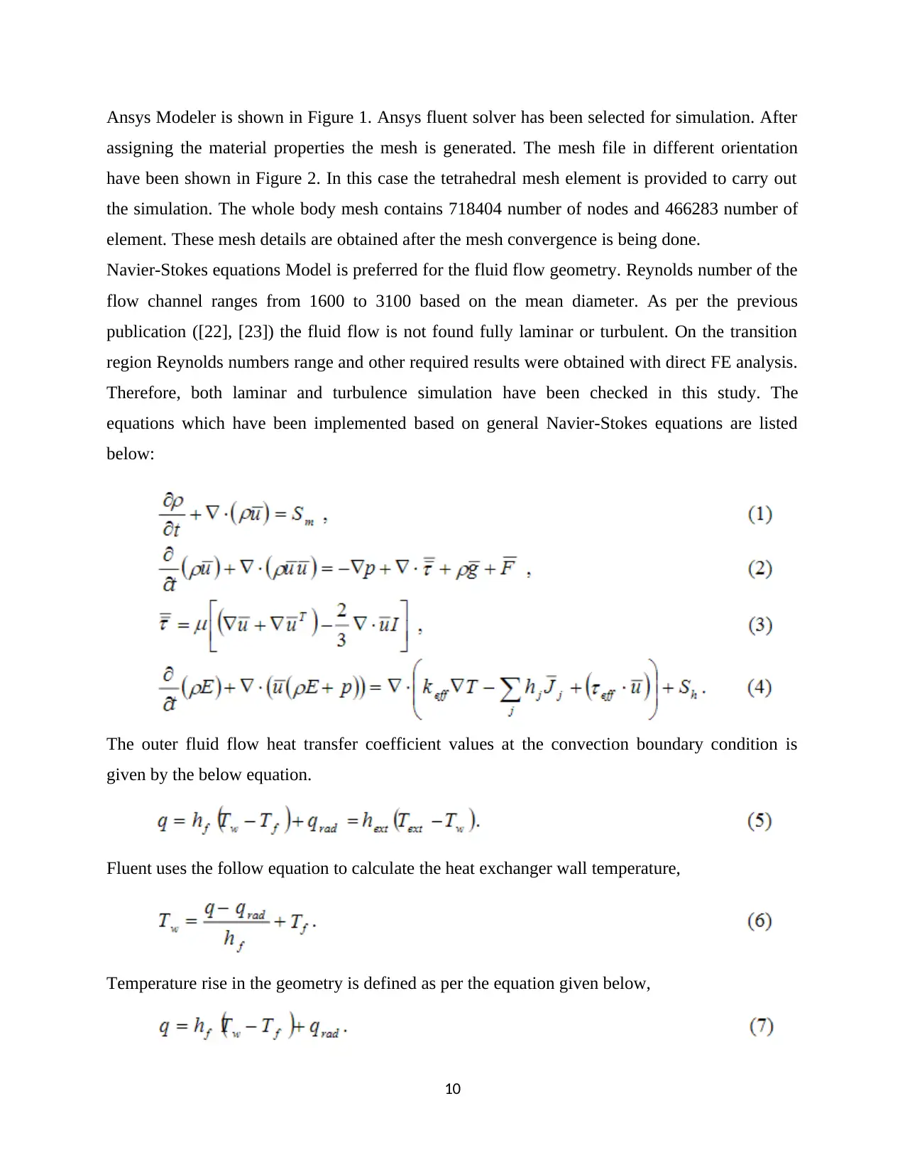
Navier-Stokes equations Model is preferred for the fluid flow geometry. Reynolds number of the
flow channel ranges from 1600 to 3100 based on the mean diameter. As per the previous
publication ([22], [23]) the fluid flow is not found fully laminar or turbulent. On the transition
region Reynolds numbers range and other required results were obtained with direct FE analysis.
Therefore, both laminar and turbulence simulation have been checked in this study. The
equations which have been implemented based on general Navier-Stokes equations are listed
below:
The outer fluid flow heat transfer coefficient values at the convection boundary condition is
given by the below equation.
Fluent uses the follow equation to calculate the heat exchanger wall temperature,
Temperature rise in the geometry is defined as per the equation given below,
10
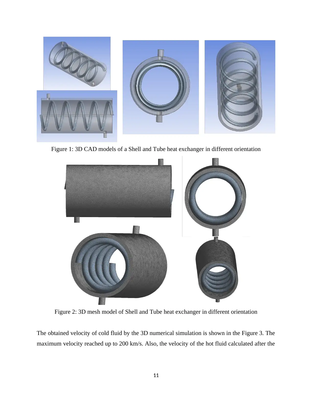
Figure 1: 3D CAD models of a Shell and Tube heat exchanger in different orientation
Figure 2: 3D mesh model of Shell and Tube heat exchanger in different orientation
The obtained velocity of cold fluid by the 3D numerical simulation is shown in the Figure 3. The
maximum velocity reached up to 200 km/s. Also, the velocity of the hot fluid calculated after the
11
Figure 2: 3D mesh model of Shell and Tube heat exchanger in different orientation
The obtained velocity of cold fluid by the 3D numerical simulation is shown in the Figure 3. The
maximum velocity reached up to 200 km/s. Also, the velocity of the hot fluid calculated after the
11
⊘ This is a preview!⊘
Do you want full access?
Subscribe today to unlock all pages.

Trusted by 1+ million students worldwide
1 out of 22
Related Documents
Your All-in-One AI-Powered Toolkit for Academic Success.
+13062052269
info@desklib.com
Available 24*7 on WhatsApp / Email
![[object Object]](/_next/static/media/star-bottom.7253800d.svg)
Unlock your academic potential
Copyright © 2020–2025 A2Z Services. All Rights Reserved. Developed and managed by ZUCOL.


