This document provides an analysis of system response, focusing on transfer function, poles, overshoots, peak time, and damping ratio. It explores the relationship between damping ratio and overshoot, and peak time and natural frequency.
Contribute Materials
Your contribution can guide someone’s learning journey. Share your
documents today.
NAME: NUMBER:
Secure Best Marks with AI Grader
Need help grading? Try our AI Grader for instant feedback on your assignments.
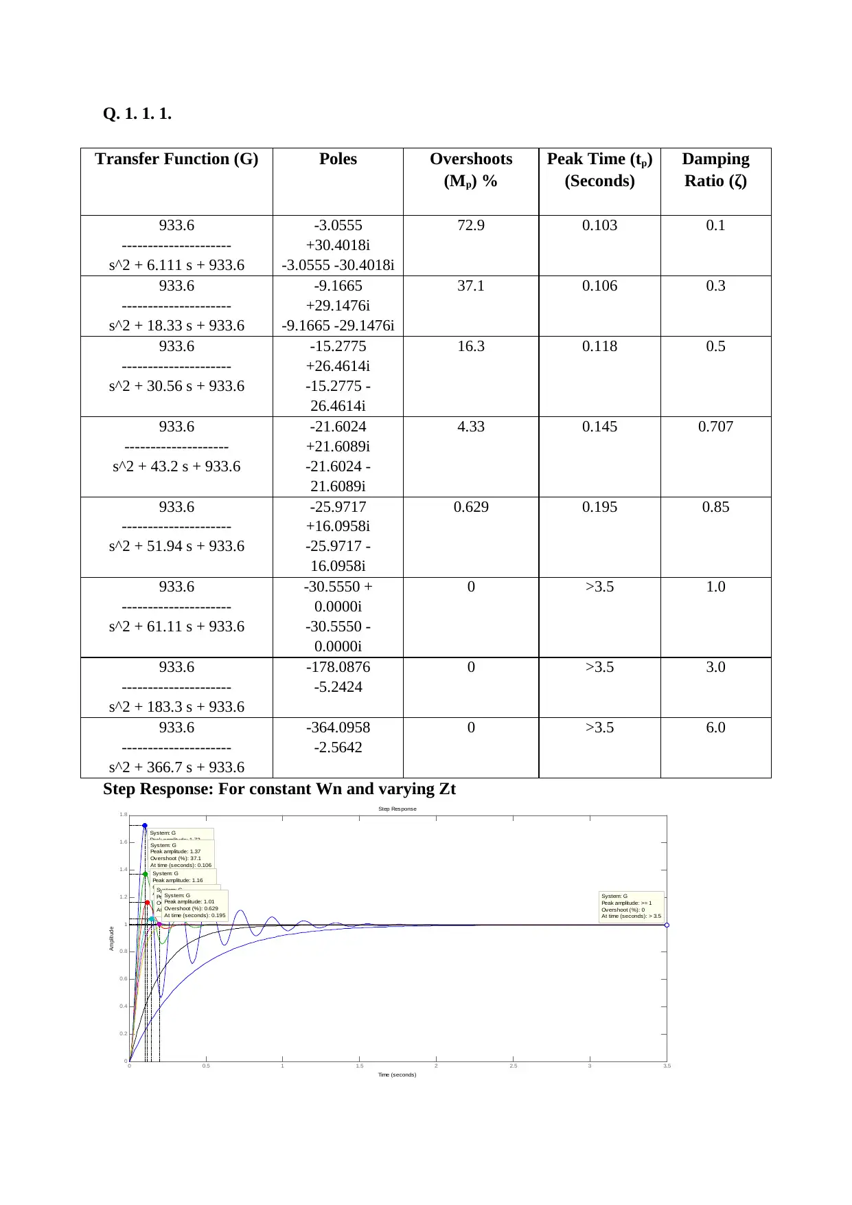
Q. 1. 1. 1. Transfer Function (G)PolesOvershoots (Mp) % Peak Time (tp) (Seconds) Damping Ratio (ζ) 933.6 --------------------- s^2 + 6.111 s + 933.6 -3.0555 +30.4018i -3.0555 -30.4018i 72.90.1030.1 933.6 --------------------- s^2 + 18.33 s + 933.6 -9.1665 +29.1476i -9.1665 -29.1476i 37.10.1060.3 933.6 --------------------- s^2 + 30.56 s + 933.6 -15.2775 +26.4614i -15.2775 - 26.4614i 16.30.1180.5 933.6 -------------------- s^2 + 43.2 s + 933.6 -21.6024 +21.6089i -21.6024 - 21.6089i 4.330.1450.707 933.6 --------------------- s^2 + 51.94 s + 933.6 -25.9717 +16.0958i -25.9717 - 16.0958i 0.6290.1950.85 933.6 --------------------- s^2 + 61.11 s + 933.6 -30.5550 + 0.0000i -30.5550 - 0.0000i 0>3.51.0 933.6 --------------------- s^2 + 183.3 s + 933.6 -178.0876 -5.2424 0>3.53.0 933.6 --------------------- s^2 + 366.7 s + 933.6 -364.0958 -2.5642 0>3.56.0 Step Response: For constant Wn and varying Zt Step Response Time (seconds) Amplitude 00.511.522.533.5 0 0.2 0.4 0.6 0.8 1 1.2 1.4 1.6 1.8 System: G Peak amplitude: 1.73 Overshoot (%): 72.9 At time (seconds): 0.103 System: G Peak amplitude: 1.37 Overshoot (%): 37.1 At time (seconds): 0.106 System: G Peak amplitude: 1.16 Overshoot (%): 16.3 At time (seconds): 0.118 System: G Peak amplitude: 1.04 Overshoot (%): 4.33 At time (seconds): 0.145 System: G Peak amplitude: 1.01 Overshoot (%): 0.629 At time (seconds): 0.195 System: G Peak amplitude: >= 1 Overshoot (%): 0 At time (seconds): > 3.5
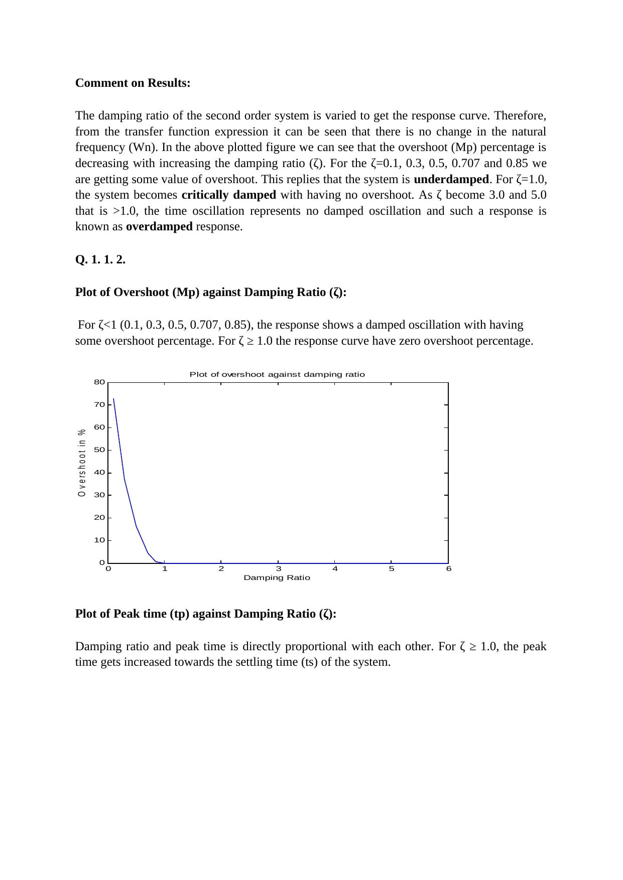
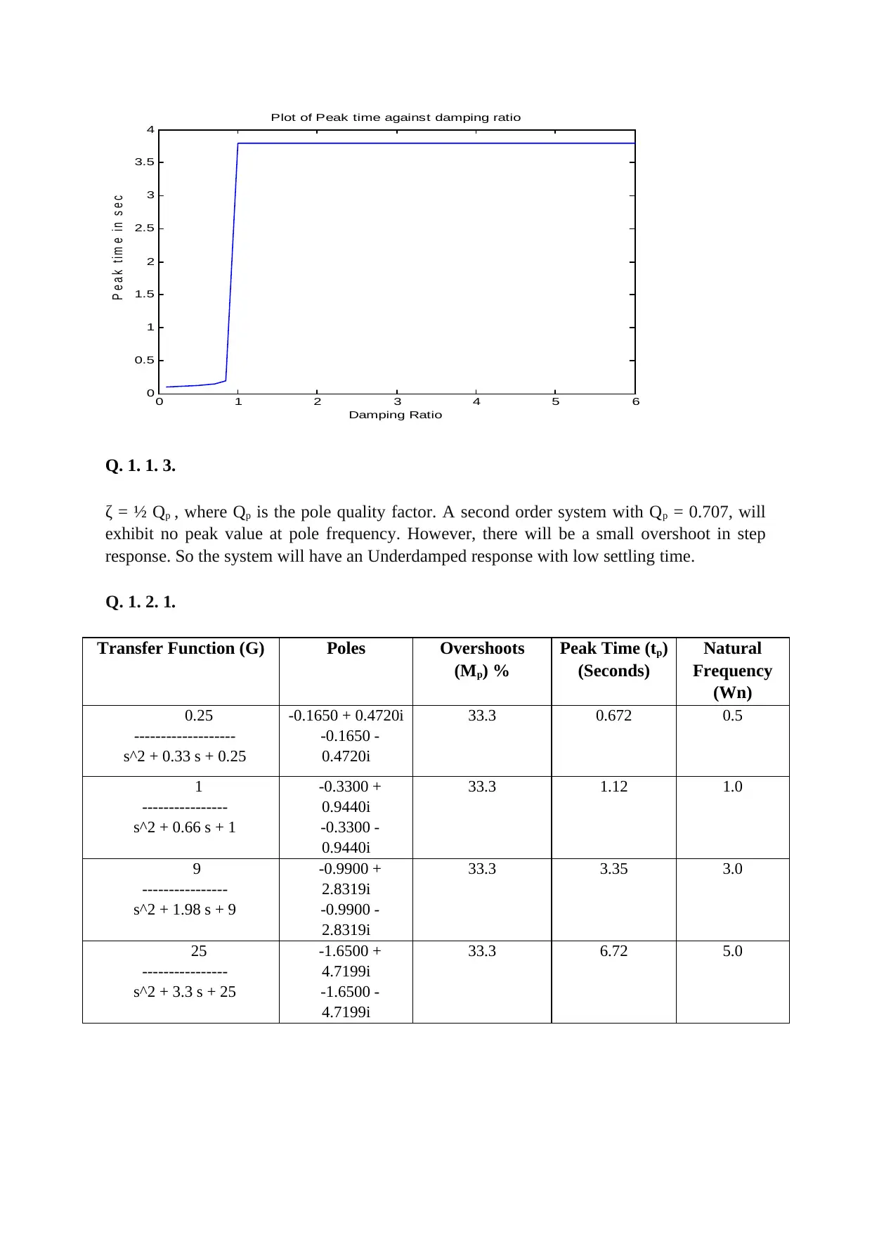
Comment on Results: The damping ratio of the second order system is varied to get the response curve. Therefore, from the transfer function expression it can be seen that there is no change in the natural frequency (Wn). In the above plotted figure we can see that the overshoot (Mp) percentage is decreasing with increasing the damping ratio (ζ). For the ζ=0.1, 0.3, 0.5, 0.707 and 0.85 we are getting some value of overshoot. This replies that the system isunderdamped. For ζ=1.0, the system becomescritically dampedwith having no overshoot. As ζ become 3.0 and 5.0 that is >1.0, the time oscillation represents no damped oscillation and such a response is known asoverdampedresponse. Q. 1. 1. 2. Plot of Overshoot (Mp) against Damping Ratio (ζ): For ζ<1 (0.1, 0.3, 0.5, 0.707, 0.85), the response shows a damped oscillation with having some overshoot percentage. For ζ ≥ 1.0 the response curve have zero overshoot percentage. 0123456 0 10 20 30 40 50 60 70 80 Plot of overshoot against damping ratio Damping Ratio O v e r s h o o ti n% Plot of Peak time (tp) against Damping Ratio (ζ): Damping ratio and peak time is directly proportional with each other. For ζ ≥ 1.0, the peak time gets increased towards the settling time (ts) of the system.
0123456 0 0.5 1 1.5 2 2.5 3 3.5 4 Plot of Peak time against damping ratio Damping Ratio P e a kt im ei ns e c Q. 1. 1. 3. ζ = ½ Qp, where Qpis the pole quality factor. A second order system with Qp= 0.707, will exhibit no peak value at pole frequency. However, there will be a small overshoot in step response. So the system will have an Underdamped response with low settling time. Q. 1. 2. 1. Transfer Function (G)PolesOvershoots (Mp) % Peak Time (tp) (Seconds) Natural Frequency (Wn) 0.25 ------------------- s^2 + 0.33 s + 0.25 -0.1650 + 0.4720i -0.1650 - 0.4720i 33.30.6720.5 1 ---------------- s^2 + 0.66 s + 1 -0.3300 + 0.9440i -0.3300 - 0.9440i 33.31.121.0 9 ---------------- s^2 + 1.98 s + 9 -0.9900 + 2.8319i -0.9900 - 2.8319i 33.33.353.0 25 ---------------- s^2 + 3.3 s + 25 -1.6500 + 4.7199i -1.6500 - 4.7199i 33.36.725.0
Paraphrase This Document
Need a fresh take? Get an instant paraphrase of this document with our AI Paraphraser
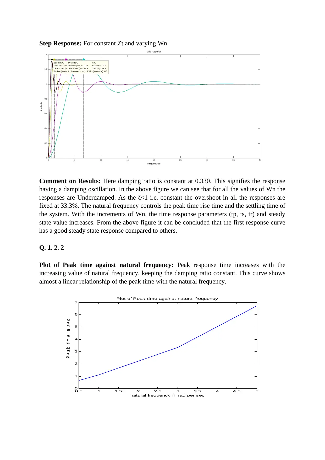
Step Response:For constant Zt and varying Wn Step Response Time (seconds) Amplitude 0510152025303540 0 0.2 0.4 0.6 0.8 1 1.2 1.4 System: G Peak amplitude: 1.33 Overshoot (%): 33.3 At time (seconds): 0.67 System: G Peak amplitude: 1.33 Overshoot (%): 33.3 At time (seconds): 6.7 System: G Peak amplitude: 1.33 Overshoot (%): 33.3 At time (seconds): 3.35 Comment on Results:Here damping ratio is constant at 0.330. This signifies the response having a damping oscillation. In the above figure we can see that for all the values of Wn the responses are Underdamped. As the ζ<1 i.e. constant the overshoot in all the responses are fixed at 33.3%. The natural frequency controls the peak time rise time and the settling time of the system. With the increments of Wn, the time response parameters (tp, ts, tr) and steady state value increases. From the above figure it can be concluded that the first response curve has a good steady state response compared to others. Q. 1. 2. 2 Plot of Peak time against natural frequency:Peak response time increases with the increasing value of natural frequency, keeping the damping ratio constant. This curve shows almost a linear relationship of the peak time with the natural frequency. 0.511.522.533.544.55 0 1 2 3 4 5 6 7 Plot of Peak time against natural frequency natural frequency in rad per sec P e a kt i m ei ns e c