Advanced Reaction Engineering CN5020: Temperature and Reaction Rate
VerifiedAdded on 2022/05/06
|11
|4026
|21
Homework Assignment
AI Summary
This homework assignment, submitted by a student from the National University of Singapore (NUS), explores the effect of temperature on reaction rate constants for the elementary reaction between hydrogen and chlorine gases. The study utilizes local optimization and thermodynamic analysis to determine the Gibbs free activation energy and reaction rate constant. The methodology involves modeling molecular structures, performing local geometry optimization, and employing nudged elastic band (NEB) calculations. The assignment also includes thermodynamic analysis to calculate Gibbs free energies at varying temperatures and a constant pressure of 1 Bar. Results are presented graphically, demonstrating the significant increase in reaction rate with increasing temperature. The report details the use of ASE package functions and Python codings, providing a comprehensive analysis of the reaction kinetics.
National University of Singapore (NUS)
Department of Chemical & Biomolecular Engineering
CN5020: Advanced Reaction Engineering
Master of Science in Chemical Engineering
AY 2020/2021 Semester 2
Week 6 Homework Assignment 3 Written Report
Title: Effect of Temperature on Reaction Rate for
Reaction between Chlorine and Hydrogen Gases
Student Name: Abdul Hannan Bin Abdul Rahman
Student Matriculation Number: A0229546W
Lecturer Name: Assistant Professor Sergey Kozlov
Submission Date: 12th March 2021
Paraphrase This Document
Need a fresh take? Get an instant paraphrase of this document with our AI Paraphraser
Page 1 of 10
Abstract
Local optimization and thermodynamic analysis were employed in this assignment to solve the
Gibbs free activation energy for an elementary reaction between hydrogen and chlorine gases.
Reaction rate constant can then be determined from this Gibbs free activation energy using a
particular reaction rate equation. Further investigation was carried out to study effect of varying
these system temperatures on the reaction rate constants at a constant pressure of 1 Bar. This
investigation was done in a Google Colab notebook, involving the use of functions from atomic
simulation environment (ASE) package and a myriad of Python codings. Results of variation
of system temperatures with reaction rates were plotted and presented in figure form. Through
analysis of this figure, it could be stated that the reaction rate constant increases significantly
with increasing temperature. Thus, reaction rate is strongly dependent on system temperature.
1. Aim and Objectives
Aim: To investigate the effect of varying system temperatures on reaction rate constants for
an elementary chemical reaction between hydrogen and chlorine gases.
Objectives:
▪ The molecular structures at each initial and final state of the chemical reaction
between chlorine and hydrogen will be modelled at specific atomic distances.
▪ The molecular structures at each initial and final state of the reaction will be locally
geometry optimized until the forces on atoms (fmax) are below 0.02 eV/Angstrom.
▪ A sequence of structures (images) composed of initial state, transition states and final
state of the reaction will be created for nudged elastic band (NEB) calculation.
▪ The nudged elastic band (NEB) calculation for structures in the list of images will be
initialized and locally optimized until forces on atoms (fmax) reach 0.2 eV/Angstrom.
▪ Molecular vibrations of structures at each initial and transition state will be calculated
first before performing thermodynamic analysis to calculate Gibbs free energies.
▪ The Gibbs free energies of structures at each initial and transition state will be calculated
at initial temperature of 300 K and pressure of 1 Bar before calculating the difference in
energy value between them to solve the reaction Gibbs free activation energy.
▪ The obtained dependency of reaction rate constants on temperatures will be plotted at
varying system temperatures between 200 to 500 K and constant pressure of 1 Bar.
Page 2 of 10
2. Methodology
This assignment work was carried out with the aim to investigate the effect of varying system
temperatures on reaction rate constants for a reaction between chlorine and chlorine gases. A
right methodological approach is needed to achieve the aim of this assignment as well as its
objectives. The overall methodology and procedures used will be described in this section. The
assignment was done on Google Colab notebook, involving the use of several functions from
ASE modules and a myriad of Python codings. All the functions that were used to solve this
assignment will also be stated in this methodology section.
The procedures of doing this assignment work start off with designing the structures of the gas
molecules at the initial and final states of the elementary reaction below:
Equation 1: Chemical Equation for Reaction between H2 and Cl2 [1]
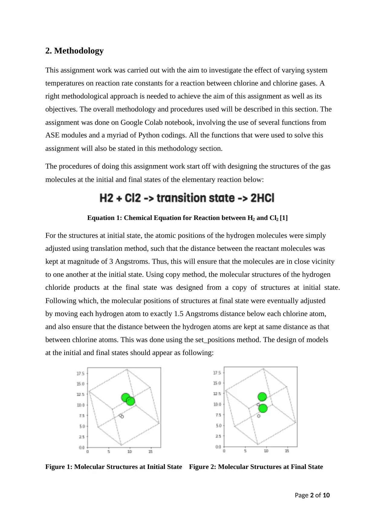
For the structures at initial state, the atomic positions of the hydrogen molecules were simply
adjusted using translation method, such that the distance between the reactant molecules was
kept at magnitude of 3 Angstroms. Thus, this will ensure that the molecules are in close vicinity
to one another at the initial state. Using copy method, the molecular structures of the hydrogen
chloride products at the final state was designed from a copy of structures at initial state.
Following which, the molecular positions of structures at final state were eventually adjusted
by moving each hydrogen atom to exactly 1.5 Angstroms distance below each chlorine atom,
and also ensure that the distance between the hydrogen atoms are kept at same distance as that
between chlorine atoms. This was done using the set_positions method. The design of models
at the initial and final states should appear as following:
Figure 1: Molecular Structures at Initial State Figure 2: Molecular Structures at Final State
⊘ This is a preview!⊘
Do you want full access?
Subscribe today to unlock all pages.

Trusted by 1+ million students worldwide
Page 3 of 10
2.1 Local Optimization
Upon completing the design of structures, a local optimization calculation was then performed
on the initial and final states using a specific algorithm. Two local optimization algorithms are
available for use which include BFGS and FIRE [2]. For this assignment, BFGS was chosen
as it is relatively easy and, also is highly efficient. From this local optimization calculation, the
values of the potential energies at the lowest potential energy surface (local minima) can be
determined. It should be noted that the local minima on this lowest surface corresponds to both
the energies of the reactants at initial state (IS) and of the products at final state (FS). The local
optimization was run for each reaction state until the forces on the atoms (fmax) are below 0.02
eV/Angstrom. Afterwards, the reaction energy between reactant and products of the elementary
gas reaction can be then obtained using get_potential_energy method.
2.2 Nudged Elastic band (NEB) Optimization
Before performing NEB optimization, a sequence of structures needs to be created as images
so that the molecular structures at intermediate steps between the reactants and products can
be easily specified. Using a series of for-loop Python codes, a myriad of images of structures
at intermediate steps was created as a result. For this assignment, the total number of images
was set at 6 (including the zeroth element in the list of images). The Python codings used for
creating these structures at intermediate steps can be found in ‘w6_homework_5020_clean.py’
file. Following which, the NEB calculation was then set up using NEB function from ase.neb
module and with the idpp interpolate method, the intermediate images were distributed equally
between the initial and final states of reaction. Finally, optimization of NEB calculation was
then performed using BFGS algorithm until values of fmax reach close to 0.2 eV/Angstrom.
This optimization was done in order to find minimum potential energy between reactants and
products and works by optimizing all the intermediate images which were created earlier along
the reaction path [3]. It should be expected that as the magnitude of the forces acting on atoms
(fmax) decreases, the values of potential energy also decreases significantly. In this assignment,
the structure at transition state (TS) was set and identified as the third element in the list of
images. Using get_potential_energy method, DFT activation energy can be found by finding
the difference between energies at initial and transition states of the reaction.
Paraphrase This Document
Need a fresh take? Get an instant paraphrase of this document with our AI Paraphraser
Page 4 of 10
2.3 Thermodynamic Analysis
The Gibbs free activation energy can be found by finding the difference between Gibbs free
energies of the initial and transition states of the reaction. Thermodynamic calculations of the
initial and final states were carried out first before calculating the Gibbs activation energy. To
perform these thermodynamic calculations, several key parameters need to be specified. These
include vibration energy, potential energy, geometry of structures, symmetry and spin numbers.
Molecular vibration calculations were performed for both the initial and transition states so as
to remove some of the lowest vibrational energies and consider only the highest energy values
as required key parameters for thermo calculation. Apart from vibrational energies, potential
(electronic) energies at IS and TS were also obtained using get_potential_energy method. The
geometries, symmetry numbers and spin numbers for the structures at IS and TS were assumed
to be as linear, 2 and 0 respectively. Thus, this completes our thermo calculation which can be
run using the IdealGasThermo function. The Gibbs free energies for each initial and transition
states were then eventually calculated by incorporating the get_gibbs_energy method into the
thermo function, with both system temperature and pressure assumed to be at 300 K and 1 Bar
respectively. The difference in values between these energies can then be recorded as the Gibbs
free activation of the elementary gas reaction in unit eV. Since reaction between chlorine and
hydrogen is highly exothermic [4], it could be expected that the value of Gibbs free activation
energy to be negative as a result.
2.4 Determination of Reaction Rate Constants
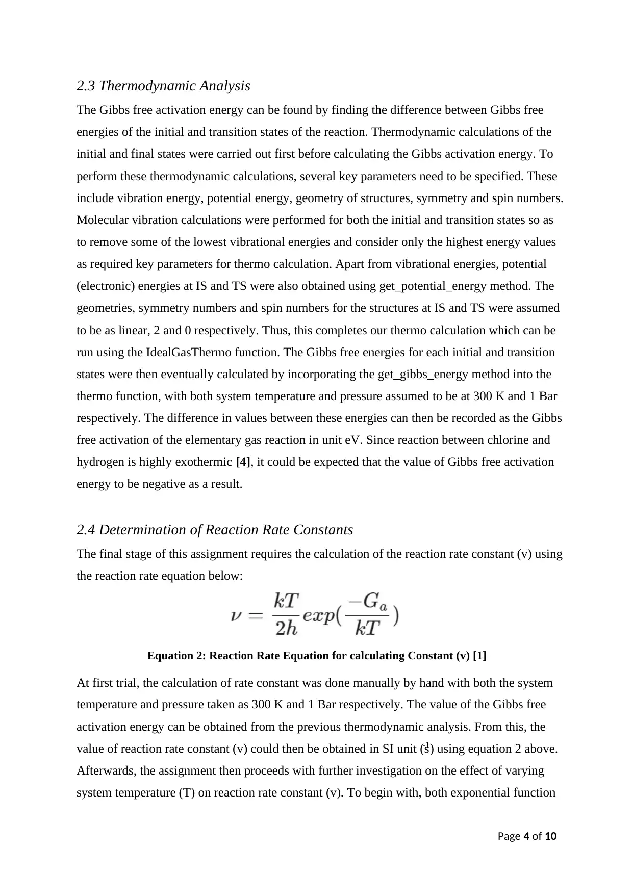
The final stage of this assignment requires the calculation of the reaction rate constant (v) using
the reaction rate equation below:
Equation 2: Reaction Rate Equation for calculating Constant (v) [1]
At first trial, the calculation of rate constant was done manually by hand with both the system
temperature and pressure taken as 300 K and 1 Bar respectively. The value of the Gibbs free
activation energy can be obtained from the previous thermodynamic analysis. From this, the
value of reaction rate constant (v) could then be obtained in SI unit (s-1) using equation 2 above.
Afterwards, the assignment then proceeds with further investigation on the effect of varying
system temperature (T) on reaction rate constant (v). To begin with, both exponential function
Page 5 of 10
and Boltzmann constant unit were imported from numpy and ase.units modules respectively.
Next, the varying system temperatures were set in the range between 200 K and 500 K, with
temperature interval of 10 K. Afterwards, an iterative-loop calculation of equation 2 was then
performed with right Python codings to determine the values of rate constant (v) at each of the
varying system temperature. The system pressure was kept constant at 1 Bar throughout the
variation of temperatures, assuming an isobaric system in this calculation. The Python codings
used for the iterative-loop calculation can be found in the ‘w6_homework_5020_clean.py’ file.
Upon calculating the reaction rate constants, a graph of the varying reaction rate constants (y-
axis) as function of system temperatures (x-axis) was plotted and displayed using matplotlib
function. The results shown in this graph will then be observed for analysis on the effect of the
system temperatures on the reaction rate constants. Through analysis of this graph, it is possible
to establish the relationship between system temperature and rate constant. According to the
thermodynamics of Transition state Theory (TST), it is stated that the reaction rate constant is
strongly dependent on system temperature [5]. Thus, this implies that if system temperature
increases, the reaction rate constant will also increase significantly. The results obtained in this
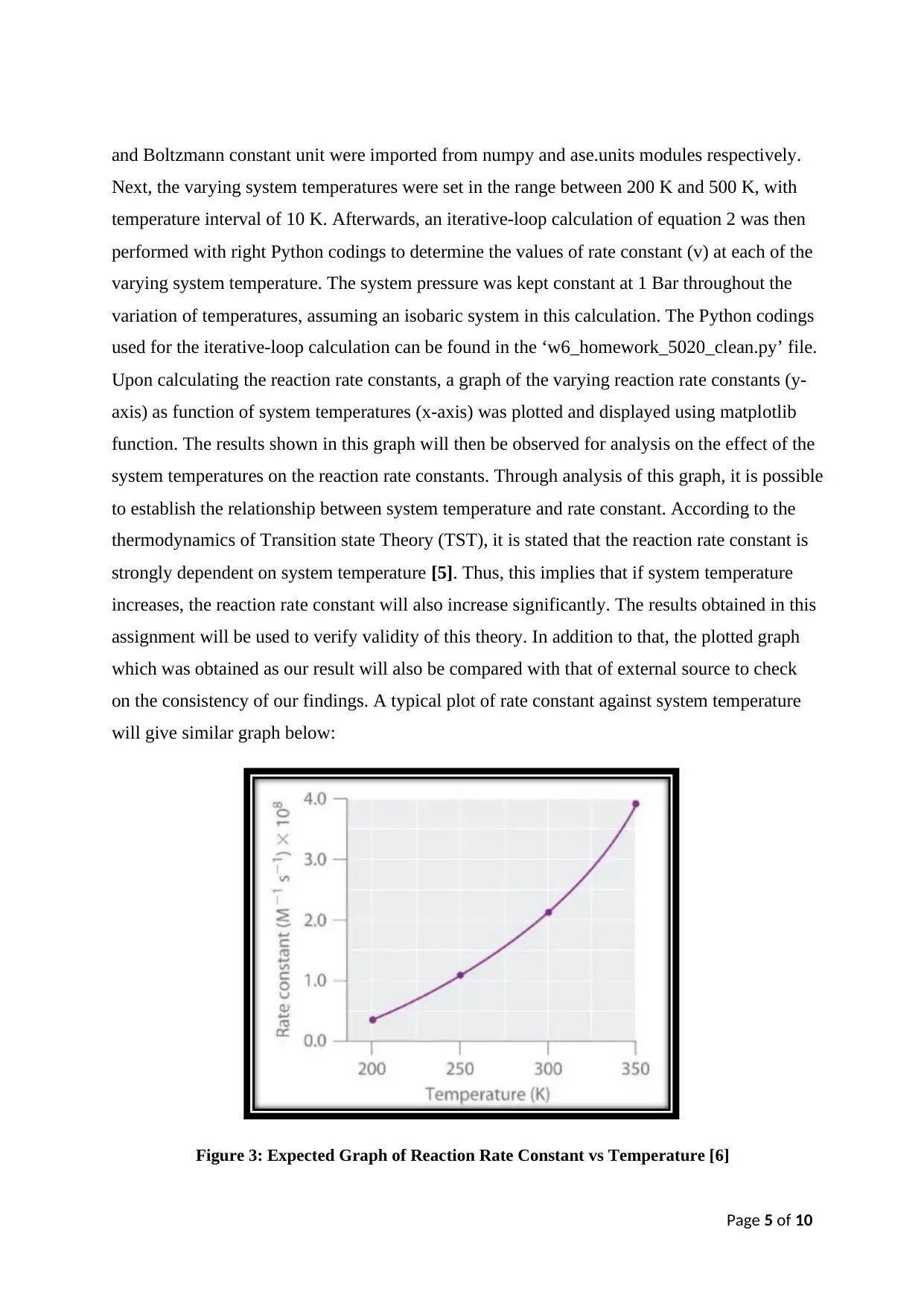
assignment will be used to verify validity of this theory. In addition to that, the plotted graph
which was obtained as our result will also be compared with that of external source to check
on the consistency of our findings. A typical plot of rate constant against system temperature
will give similar graph below:
Figure 3: Expected Graph of Reaction Rate Constant vs Temperature [6]
⊘ This is a preview!⊘
Do you want full access?
Subscribe today to unlock all pages.

Trusted by 1+ million students worldwide
Page 6 of 10
3. Results and Discussion
The results obtained from the assignment work will be presented and discussed in this section.
Here is where we will analyse and discuss the results of the local optimization calculations, the
thermodynamic potential calculations, the variation of rate constants with system temperatures,
and finally, all the figures which were plotted in Google Colab notebook. The following figures
below were obtained as our results:
Upon designing the molecular structures at both the initial and final states, a local optimization
calculation was performed for each structure using the BFGS algorithm to determine the lowest
potential energies, where the forces acting on atoms (fmax) are below 0.02 eV/Angstrom. The
lowest potential energies for the initial and final states were recorded as -7.226 eV and -8.529
eV respectively. During this local optimization, atoms are being displaced by the forces acting
on them. As the atoms move on the potential energy surface (PES), subsequently this result in
a chemical reaction occurring between the hydrogen and chlorine reactants to form hydrogen
chloride products. Using get_potential_energy method, the DFT reaction energy between these
reactants and products can then be calculated and was obtained as -1.303 eV.
A sequence of intermediate structures between the initial and final states was created as images
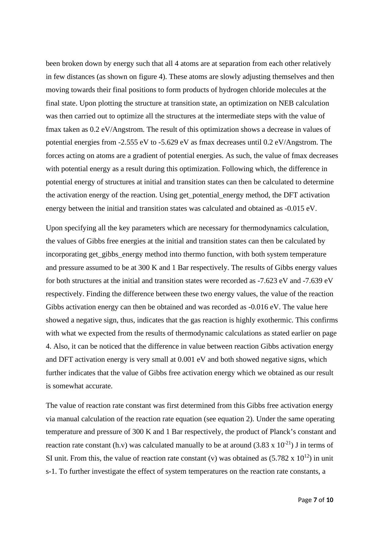
using a series of for-loop Python codes. Figure 4 above shows the molecular structure at the
transition state for the elementary gas reaction between chlorine and hydrogen molecules (see
equation 1). This molecular structure above was plotted using plot_atoms function at a rotation
of ‘0x,90y,0z’ and radii of 0.75, with the iterative (i) value taken as 3 (third element in the list
of images). After a reaction occurs, the bonds between molecules of hydrogen and chlorine had
Figure 4: Molecular Structure at
Transition State (TS)
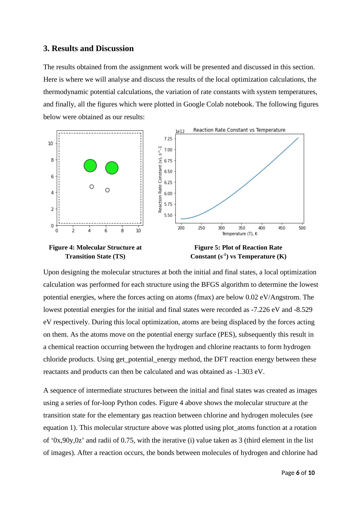
Figure 5: Plot of Reaction Rate
Constant (s-1) vs Temperature (K)
Paraphrase This Document
Need a fresh take? Get an instant paraphrase of this document with our AI Paraphraser
Page 7 of 10
been broken down by energy such that all 4 atoms are at separation from each other relatively
in few distances (as shown on figure 4). These atoms are slowly adjusting themselves and then
moving towards their final positions to form products of hydrogen chloride molecules at the
final state. Upon plotting the structure at transition state, an optimization on NEB calculation
was then carried out to optimize all the structures at the intermediate steps with the value of
fmax taken as 0.2 eV/Angstrom. The result of this optimization shows a decrease in values of
potential energies from -2.555 eV to -5.629 eV as fmax decreases until 0.2 eV/Angstrom. The
forces acting on atoms are a gradient of potential energies. As such, the value of fmax decreases
with potential energy as a result during this optimization. Following which, the difference in
potential energy of structures at initial and transition states can then be calculated to determine
the activation energy of the reaction. Using get_potential_energy method, the DFT activation
energy between the initial and transition states was calculated and obtained as -0.015 eV.
Upon specifying all the key parameters which are necessary for thermodynamics calculation,
the values of Gibbs free energies at the initial and transition states can then be calculated by
incorporating get_gibbs_energy method into thermo function, with both system temperature
and pressure assumed to be at 300 K and 1 Bar respectively. The results of Gibbs energy values
for both structures at the initial and transition states were recorded as -7.623 eV and -7.639 eV
respectively. Finding the difference between these two energy values, the value of the reaction
Gibbs activation energy can then be obtained and was recorded as -0.016 eV. The value here
showed a negative sign, thus, indicates that the gas reaction is highly exothermic. This confirms
with what we expected from the results of thermodynamic calculations as stated earlier on page
4. Also, it can be noticed that the difference in value between reaction Gibbs activation energy
and DFT activation energy is very small at 0.001 eV and both showed negative signs, which
further indicates that the value of Gibbs free activation energy which we obtained as our result
is somewhat accurate.
The value of reaction rate constant was first determined from this Gibbs free activation energy
via manual calculation of the reaction rate equation (see equation 2). Under the same operating
temperature and pressure of 300 K and 1 Bar respectively, the product of Planck’s constant and
reaction rate constant (h.v) was calculated manually to be at around (3.83 x 10⁻²¹) J in terms of
SI unit. From this, the value of reaction rate constant (v) was obtained as (5.782 x 10⁻¹²) in unit
s-1. To further investigate the effect of system temperatures on the reaction rate constants, a
Page 8 of 10
variation of system temperature from 200 K to 500 K was done at a temperature interval of 10
K and at a constant system pressure of 1 Bar. The values of reaction rate constants at each of
these varying system temperatures can then be determined using an iterative loop calculation
within reaction rate equation (see equation 2), involving few Python codings. Upon running
the code cell, the results of this variation showed decreasing values in the Gibbs free energies
of structures at both initial and transition states as system temperature increases from 200 K to
500 K. As shown on equation 3 below, the change in Gibbs energies (dG) of these structures
depends on the product of temperature and negative change in entropy (-TdS). As temperature
increases, the value of (-TdS) becomes more negative which subsequently, results in decreasing
Gibbs free energy of structures. Hence for structures at initial and transition states, the values
of Gibbs free energy decreases with increasing temperature.
𝒅𝑮 = 𝒅𝑯 − 𝑻𝒅𝑺
Equation 3: Gibbs Free Energy Change Equation
Moving on from this, a graph of reaction rate constants against the varying system temperatures
(see figure 5) was plotted and obtained as a result. Observing this figure, it can be seen that the
reaction rate constant increases drastically as the temperature gradually starts to increase from
200 K, resulting in a curve shape-like figure which is almost close to being a linear. This figure
which we obtained as our result is also consistent with our expected figure from that of external
source (see figure 3) as both graphs show slightly similar trends. Also in theory, it was stated
that an increase in system temperature leads to significant increase in reaction rates (see page
5). Based on result shown on figure 5, reaction rate constant increases as system temperature
increases. Thus, this confirms and supports with what has been stated by the theory earlier. The
significant increase in reaction rates is due to average increase in the atomic kinetic energy
which is caused by more absorption of hear energy supplied at a high system temperature. On
the other hand, if temperature decreases significantly, the Gibbs activation energy will almost
approach to zero and the exponential term on equation 2 will then become one. Subsequently,
this will result in a minimum value of reaction rate constant. Thus, the reaction rate constants
are strongly dependent on system temperatures. From this, we can then make final conclusive
statement on the effect of varying temperatures on reaction rate constants for the elementary
reaction between hydrogen and chlorine molecules.
⊘ This is a preview!⊘
Do you want full access?
Subscribe today to unlock all pages.

Trusted by 1+ million students worldwide
Page 9 of 10
4. Conclusion
In conclusion, the aim of this assignment work has finally been achieved and its objectives
have also been fulfilled. The aim to investigate the effect of temperature on the reaction rate
constant for an elementary gas reaction between chlorine and hydrogen gases. The procedures
utilised to achieve this aim, involved performing local optimization calculation on structures
at initial and final states, performing NEB optimization calculation on structures at intermediate
steps between reactants and products, calculating thermodynamic potentials (Gibbs energies)
of structures at the initial and transition states to find the value of Gibbs activation energy and
lastly, determining value of reaction rate constant via manual calculation of the reaction rate
equation (equation 2) at constant system temperature of 300 K, followed by varying this system
temperature in the range between 200 K and 500 K to investigate its effect on the reaction rate
constants using the iterative-loop calculation of equation 2. While working on this assignment,
several functions from the atomic simulation environment (ASE) modules, in addition to a
myriad of Python codings were all used to carry out the aforementioned work procedures in
Google Colab notebook.
Upon calculating the reaction rate constants at varying system temperatures, a graph of reaction
rate constants (y-axis) as function of system temperatures (x-axis) was plotted and displayed
using matplotlib function. The results shown in this graph will then be observed for analysis
on the effect of the system temperatures on the reaction rate constants. Observing figure 5, it
can be seen that the reaction rate constant increases drastically as the temperature gradually
starts to increase from 200 K, resulting in curve shape-like figure which is almost close to being
a linear. Theoretically, it was also stated that an increase in the system temperature will lead to
a significant increase in the reaction rates (see page 5). Based on result shown on figure 5, the
reaction rate constant increases as the system temperature increases. Thus, this confirms and
supports with the theory above. The significant increase in reaction rates is due to the average
increase in atomic kinetic energy which is caused by more absorption of hear energy supplied
at high system temperature. From this, it can then be concluded that reaction rates of elementary
gas reaction between chlorine and hydrogen are strongly dependent on system temperatures,
and that as value of system temperatures increases from 200 K to 500 K, the value of reaction
rate constants will then also subsequently increase as a result.
Paraphrase This Document
Need a fresh take? Get an instant paraphrase of this document with our AI Paraphraser
Page 10 of 10
References
1. Colab.research.google.com. 2021. Google Colaboratory. [online] Available at:
<https://colab.research.google.com/drive/10HZiqjHRB8EppNVH7vpGfNeXenV9CtuU>
[Accessed 8 March 2021].
2. Wiki.fysik.dtu.dk. 2021. Structure optimization — ASE documentation. Available at:
<https://wiki.fysik.dtu.dk/ase/ase/optimize.html?highlight=bfgs#ase.optimize.BFGS>
[Accessed 7 March 2021].
3. Theory.cm.utexas.edu. 2021. Nudged Elastic Band — Transition State Tools for VASP.
Available at: <https://theory.cm.utexas.edu/vtsttools/neb.html> [Accessed 7 March 2021].
4. Gcsescience.com. 2021. GCSE CHEMISTRY - What is a Bond Energy?
Available at: <https://www.gcsescience.com/rc23-bond-energy-calculation.htm>
[Accessed 7 March 2021].
5. Chemistry LibreTexts. 2021. 9.7: Theories of Reaction Rates. Available at:
<https://chem.libretexts.org/Bookshelves/Physical_and_Theoretical_Chemistry_Textbook_M
aps/Map%3A_Physical_Chemistry_for_the_Biosciences_(Chang)/09%3A_Chemical_Kinetic
s/9.07%3A_Theories_of_Reaction_Rates> [Accessed 8 March 2021].
6. Chemistry LibreTexts. 2021. 4.8: Temperature and Rate. [online] Available at:
<https://chem.libretexts.org/Courses/University_of_California_Davis/UCD_Chem_002C/UC
D_Chem_2C%3A_Larsen/Text/Unit_4%3A_Chemical_Kinetics/4.08%3A_Temperature_and
_Rate> [Accessed 10 March 2021].
1 out of 11
Your All-in-One AI-Powered Toolkit for Academic Success.
+13062052269
info@desklib.com
Available 24*7 on WhatsApp / Email
![[object Object]](/_next/static/media/star-bottom.7253800d.svg)
Unlock your academic potential
Copyright © 2020–2025 A2Z Services. All Rights Reserved. Developed and managed by ZUCOL.
