Network Analysis and Design for Desklib Online Library
VerifiedAdded on 2023/06/12
|29
|5615
|385
AI Summary
This report provides details on network infrastructure and protocols, addressing, security, and remote access for Desklib online library. It includes cable requirements, comparison of hub, switch, wireless access point, and router, IP and MAC addressing, and more.
Contribute Materials
Your contribution can guide someone’s learning journey. Share your
documents today.
Running head: NETWORK ANALYSIS AND DESIGN
Network Analysis and Design
Name of Student:
Name of the University:
Author Note
Network Analysis and Design
Name of Student:
Name of the University:
Author Note
Secure Best Marks with AI Grader
Need help grading? Try our AI Grader for instant feedback on your assignments.
1
NETWORK ANALYSIS AND DESIGN
Table of Contents
Introduction......................................................................................................................................2
Task 1: Network Infrastructure and Protocols.................................................................................2
Cable requirement........................................................................................................................2
The comparison of Hub, Switch, wireless access point and Router............................................3
The OSI model has 7 layers and supports 2 running process in the network. the description
about the layers are provided below:...........................................................................................7
The protocols used by the 7 layers of the OSI model is provided below:...................................8
Task 2: Addressing..........................................................................................................................9
Network components addressing.................................................................................................9
Private IPv4 address and a public IPv4 address........................................................................10
DHCP explanation.....................................................................................................................11
ARP explanation........................................................................................................................12
Default Gateway and Subnet Mask...........................................................................................12
IP Routing Table........................................................................................................................13
Task 3: Security.............................................................................................................................13
Task 4: Diagram and explanation..................................................................................................14
Network Topology.....................................................................................................................14
IPv4 address allocation..............................................................................................................15
Selection of hardware components............................................................................................17
2
NETWORK ANALYSIS AND DESIGN
Prices of the recommended hardware........................................................................................17
Task 5: Remote access...................................................................................................................22
Remote access security..............................................................................................................22
Dropbox justification.................................................................................................................22
Impact of remote access on the system......................................................................................23
Bibliography..................................................................................................................................24
3
NETWORK ANALYSIS AND DESIGN
Introduction
The reports deals with the details of the Family counts Charity network development. The
organization provides the clients with services like information, advice, advocacy and legal
representation. The company has expanded over the last 18 years since it was created and the
network of the company has also been expanding from the time of creation. However lately the
need for a secured network has developed in the organization and also the organization is
looking to expand the network and also set up a new network that would be improving the
security and efficiency of the network. The report contains description of 5 tasks that would be
required for the set of the network.
Task 1: Network Infrastructure and Protocols
Cable requirement
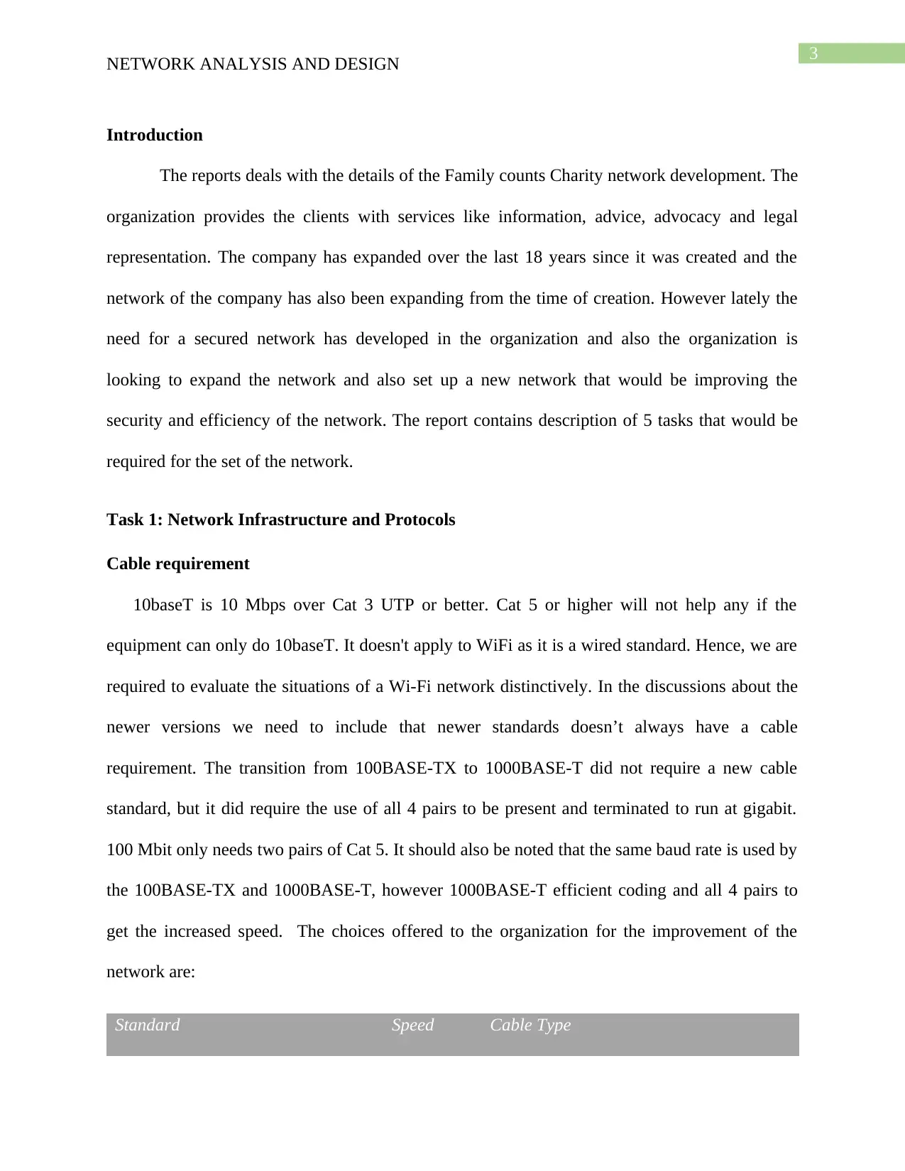
10baseT is 10 Mbps over Cat 3 UTP or better. Cat 5 or higher will not help any if the
equipment can only do 10baseT. It doesn't apply to WiFi as it is a wired standard. Hence, we are
required to evaluate the situations of a Wi-Fi network distinctively. In the discussions about the
newer versions we need to include that newer standards doesn’t always have a cable
requirement. The transition from 100BASE-TX to 1000BASE-T did not require a new cable
standard, but it did require the use of all 4 pairs to be present and terminated to run at gigabit.
100 Mbit only needs two pairs of Cat 5. It should also be noted that the same baud rate is used by
the 100BASE-TX and 1000BASE-T, however 1000BASE-T efficient coding and all 4 pairs to
get the increased speed. The choices offered to the organization for the improvement of the
network are:
Standard Speed Cable Type
Secure Best Marks with AI Grader
Need help grading? Try our AI Grader for instant feedback on your assignments.
4
NETWORK ANALYSIS AND DESIGN
10Base-T 10 Mbps Cat 5
100Base-TX (Fast Ethernet) 100 Mbps Cat 5e
1000Base-T (Gigabit Ethernet) 1 Gbps Cat 5e or better (Cat 6, 6A...)
10GBase-T (10 Gigabit Ethernet) 10 Gbps Cat 6A, or Cat 6 (limited to 55 meters)
In addition to the above mentioned options the options regarding the wireless network is
described below. Typically an organization should try to implement a network that is mostly
wired. In addition to the wired network the wireless access points to the network should be added
according to the requirement of the organization. There are various choice open to the
organization for the setup of the wireless network access in the network. There are different
frequencies used (2.4 or 5 GHz typically), which standard of 802.11 (examples include 802.11n
or 802.11ac). The 10Base-T part stands out to me as a sort of "diversion". It should be noted that
the newer versions of Ethernet will work with older devices, so a 10Base-T device will work just
fine on a network that supports Gigabit speeds; however, that link will be limited to 10 Mbps. On
another note, Cat 5 (not 5e) cable is basically obsolete. Cat 5e is still very common, hence it is
recommended that the Cat 6 or the Cat 6A cables are used for the network and this would
provide the network with a scope to accommodate future use of 10 Gigabit Ethernet, and
applications using Power over Ethernet to provide power to Wi-Fi access points.
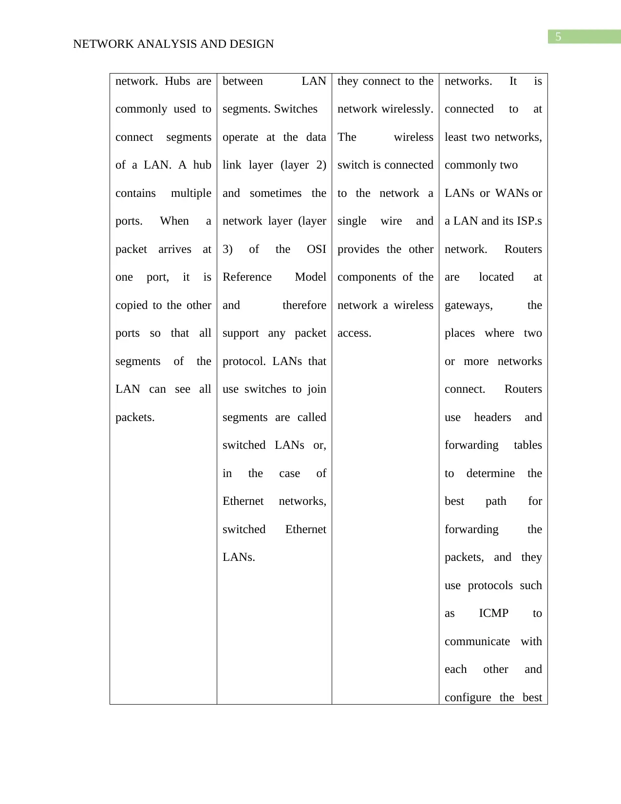
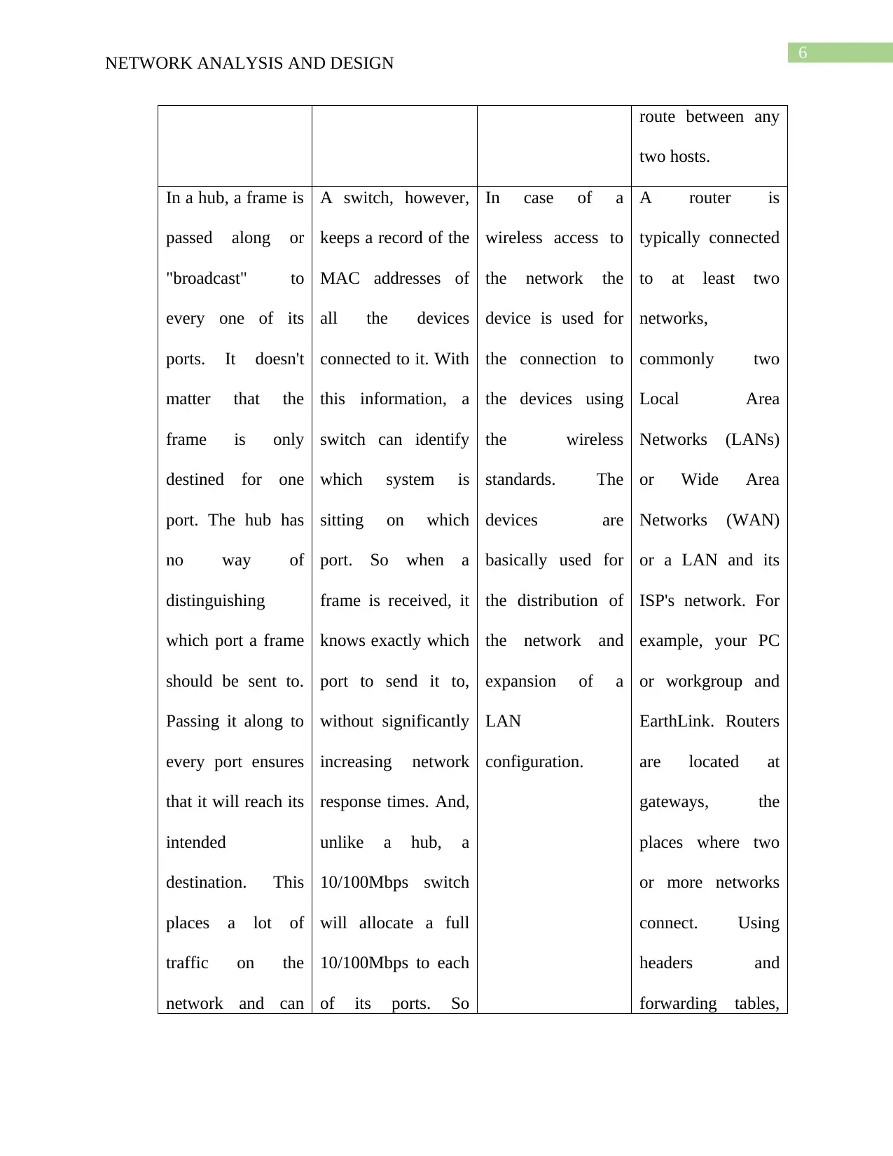
The comparison of Hub, Switch, wireless access point and Router
HUB SWITCH WIRELESS
ACCES POINT
ROUTER
A common
connection point
for devices in a
In networks, a
device that filters
and forwards packets
The wireless access
points are similar
to the switches
This device
forwards data
packets along
5
NETWORK ANALYSIS AND DESIGN
network. Hubs are
commonly used to
connect segments
of a LAN. A hub
contains multiple
ports. When a
packet arrives at
one port, it is
copied to the other
ports so that all
segments of the
LAN can see all
packets.
between LAN
segments. Switches
operate at the data
link layer (layer 2)
and sometimes the
network layer (layer
3) of the OSI
Reference Model
and therefore
support any packet
protocol. LANs that
use switches to join
segments are called
switched LANs or,
in the case of
Ethernet networks,
switched Ethernet
LANs.
they connect to the
network wirelessly.
The wireless
switch is connected
to the network a
single wire and
provides the other
components of the
network a wireless
access.
networks. It is
connected to at
least two networks,
commonly two
LANs or WANs or
a LAN and its ISP.s
network. Routers
are located at
gateways, the
places where two
or more networks
connect. Routers
use headers and
forwarding tables
to determine the
best path for
forwarding the
packets, and they
use protocols such
as ICMP to
communicate with
each other and
configure the best
6
NETWORK ANALYSIS AND DESIGN
route between any
two hosts.
In a hub, a frame is
passed along or
"broadcast" to
every one of its
ports. It doesn't
matter that the
frame is only
destined for one
port. The hub has
no way of
distinguishing
which port a frame
should be sent to.
Passing it along to
every port ensures
that it will reach its
intended
destination. This
places a lot of
traffic on the
network and can
A switch, however,
keeps a record of the
MAC addresses of
all the devices
connected to it. With
this information, a
switch can identify
which system is
sitting on which
port. So when a
frame is received, it
knows exactly which
port to send it to,
without significantly
increasing network
response times. And,
unlike a hub, a
10/100Mbps switch
will allocate a full
10/100Mbps to each
of its ports. So
In case of a
wireless access to
the network the
device is used for
the connection to
the devices using
the wireless
standards. The
devices are
basically used for
the distribution of
the network and
expansion of a
LAN
configuration.
A router is
typically connected
to at least two
networks,
commonly two
Local Area
Networks (LANs)
or Wide Area
Networks (WAN)
or a LAN and its
ISP's network. For
example, your PC
or workgroup and
EarthLink. Routers
are located at
gateways, the
places where two
or more networks
connect. Using
headers and
forwarding tables,
Paraphrase This Document
Need a fresh take? Get an instant paraphrase of this document with our AI Paraphraser
7
NETWORK ANALYSIS AND DESIGN
lead to poor
network response
times.
regardless of the
number of PCs
transmitting, users
will always have
access to the
maximum amount of
bandwidth. It's for
these reasons a
switch is considered
to be a much better
choice than a hub.
routers determine
the best path for
forwarding the
packets. Router use
protocols such as
ICMP to
communicate with
each other and
configure the best
route between any
two hosts.
Explanation of the Hub, Switch, wireless access point and Router
Hub
The hub is used in the physical layer or below in the OSI model as it is the device that
connects all the layers and connect it to a form a single network topology.
Switch
The switch is used in the both the data link layer and the network layer as the devices is
used for the connection among the different peripherals in the network and helps in configuring
the mac address and the IP addresses of the components in the network.
Router
8
NETWORK ANALYSIS AND DESIGN
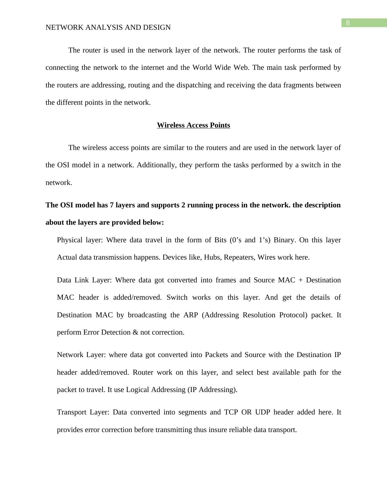
The router is used in the network layer of the network. The router performs the task of
connecting the network to the internet and the World Wide Web. The main task performed by
the routers are addressing, routing and the dispatching and receiving the data fragments between
the different points in the network.
Wireless Access Points
The wireless access points are similar to the routers and are used in the network layer of
the OSI model in a network. Additionally, they perform the tasks performed by a switch in the
network.
The OSI model has 7 layers and supports 2 running process in the network. the description
about the layers are provided below:
Physical layer: Where data travel in the form of Bits (0’s and 1’s) Binary. On this layer
Actual data transmission happens. Devices like, Hubs, Repeaters, Wires work here.
Data Link Layer: Where data got converted into frames and Source MAC + Destination
MAC header is added/removed. Switch works on this layer. And get the details of
Destination MAC by broadcasting the ARP (Addressing Resolution Protocol) packet. It
perform Error Detection & not correction.
Network Layer: where data got converted into Packets and Source with the Destination IP
header added/removed. Router work on this layer, and select best available path for the
packet to travel. It use Logical Addressing (IP Addressing).
Transport Layer: Data converted into segments and TCP OR UDP header added here. It
provides error correction before transmitting thus insure reliable data transport.
9
NETWORK ANALYSIS AND DESIGN
a) UDP Protocol - unreliable & connectionless, used in LIVE SCENARIOS.
b) TCP Protocol - reliable because of 3-way handshake, flow control.
Session Layer: This layer establishes, manages, and terminates sessions between Peer to
Peer. It keep different application’s data separate from other applications.
Presentation Layer: It ensures that data transferred from application layer of one system can
be read by application layer of other system. It’s responsible for converting data into standard
format which may include:
JPEG, MPEG, BMP, MIDI, WAV, MP3
Tasks which can be performed:
a) Encryption >< Decryption
b) Encoding >< Decoding
Application Layer: It is basically the user interface of the network. This layer is concerned
with user interaction with the computer and the network. It acts as an interface between the
actual application programs. Contains many protocols and utilities, such as telnet, FTP,
HTTP, SMTP. A port number is a way to identify a specific process to which an Internet or
other network message is to be forwarded when it arrives at a server.
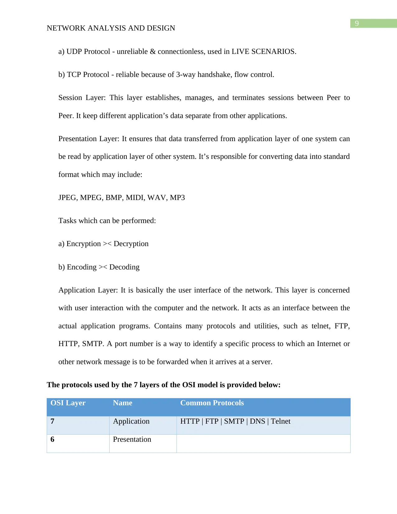
The protocols used by the 7 layers of the OSI model is provided below:
OSI Layer Name Common Protocols
7 Application HTTP | FTP | SMTP | DNS | Telnet
6 Presentation
Secure Best Marks with AI Grader
Need help grading? Try our AI Grader for instant feedback on your assignments.
10
NETWORK ANALYSIS AND DESIGN
5 Session
4 Transport TCP | SPX
3 Network IP | IPX
2 Data Link Ethernet
1 Physical
Task 2: Addressing
Network components addressing
The IP address and the MAC addresses of the components in the network are assigned
distinctly and hence they have their respective differences. The differences in between the IP
addresses and the MAC addresses are:
Features IP Address MAC Address
Purpose IP Address is an Internet Protocol
Address that defines a connection in
between computers connected to the
Internet.
MAC Address is basically Media
Access Control that defines physical
address of computer connected on
internet.
Address Internet Protocol Address is
generally signed by network
administrator or are signed by
Internet Service Provider.
The MAC Address is generally
assigned by manufacturer of the NIC
card.
Retrieve
Address
RARP protocol is able to retrieve the
IP addresses of device.
ARP protocol generally can retrieve
the MAC address of a particular
11
NETWORK ANALYSIS AND DESIGN
device.
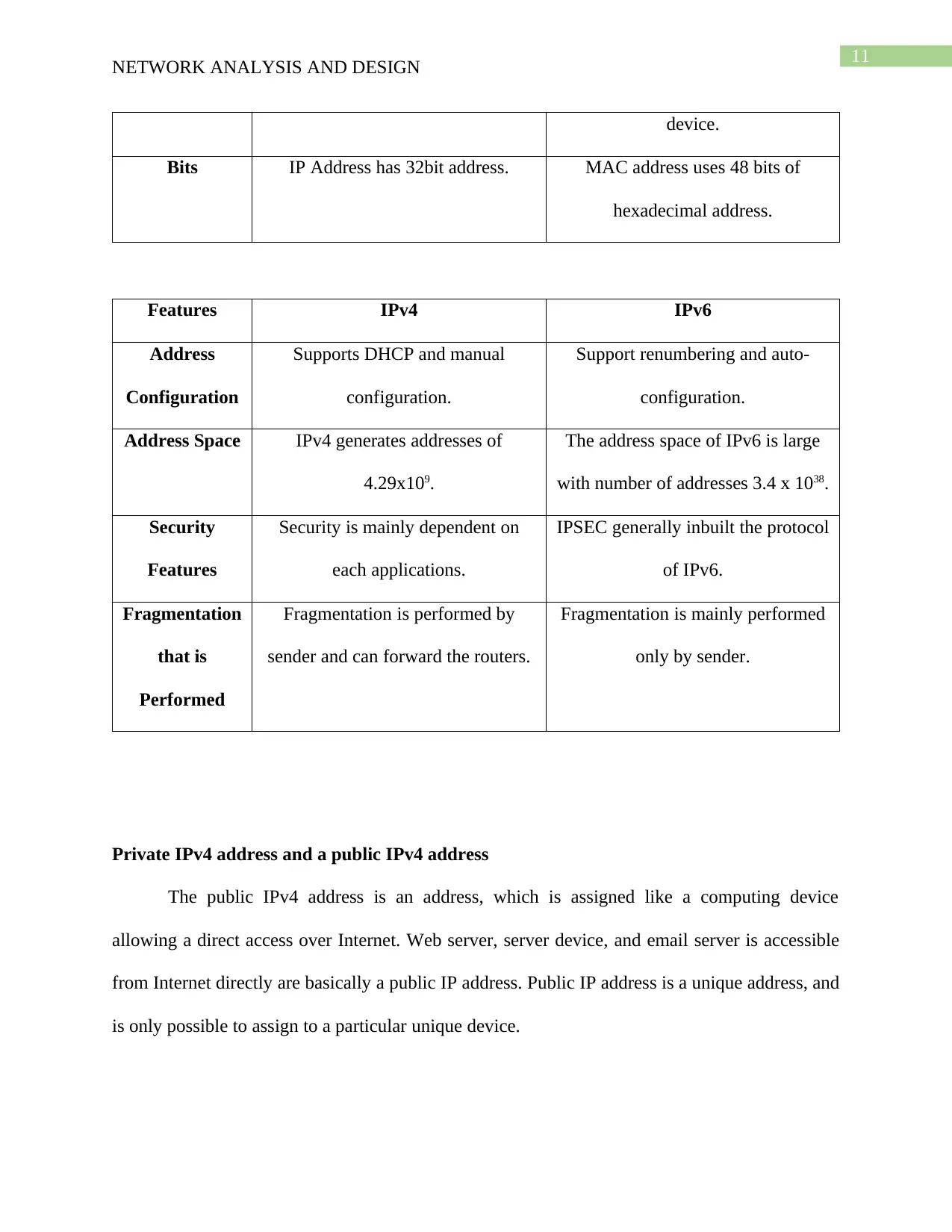
Bits IP Address has 32bit address. MAC address uses 48 bits of
hexadecimal address.
Features IPv4 IPv6
Address
Configuration
Supports DHCP and manual
configuration.
Support renumbering and auto-
configuration.
Address Space IPv4 generates addresses of
4.29x10⁹.
The address space of IPv6 is large
with number of addresses 3.4 x 1038.
Security
Features
Security is mainly dependent on
each applications.
IPSEC generally inbuilt the protocol
of IPv6.
Fragmentation
that is
Performed
Fragmentation is performed by
sender and can forward the routers.
Fragmentation is mainly performed
only by sender.
Private IPv4 address and a public IPv4 address
The public IPv4 address is an address, which is assigned like a computing device
allowing a direct access over Internet. Web server, server device, and email server is accessible
from Internet directly are basically a public IP address. Public IP address is a unique address, and
is only possible to assign to a particular unique device.
12
NETWORK ANALYSIS AND DESIGN
Private Internet Protocol address is an address space that is allocated by InterNIC. The
InterNIC allows the organizations to make their private network. There are basically three IP
blocks known as Class A, Class B, and Class C blocks that are reserved for private use only. The
computers, smartphones, and tablets that are used in daily life for personal use or for
organizational use basically use private Internet Protocol Addresses that are assigned to them. A
printer also has a private network that helps in printing.
The range of private IPv4 address are as follows:
RFC1918
name
Range of IP
Address
Total
Number
of
Addresses
Size of
Host
ID
Subnet Mask Mask
Bits
Description
Block of
24-bit
10.0.0.0 –
10.255.255.255
16,777,216 24bits 10.0.0.0/8
(255.0.0.0)
8 bits Class A
Network
Block of
20-bit
172.16.0.0 –
172.31.255.255
1,048,576 20bits 172.16.0.0/12
(255.240.0.0)
12 bits Class B
Network
Block of
16-bit
192.168.0.0 –
192.168.255.25
5
65,536 16bits 192.168.0.0/16
(255.255.0.0)
16 bits Class C
Network
DHCP explanation
Dynamic Host Configuration Protocol (DHCP) is considered as a protocol of network
management that is used dynamically for assigning the Internet Protocol address to any device or
to any node or to some network. This helps to communicate using a particular Internet Protocol.
Paraphrase This Document
Need a fresh take? Get an instant paraphrase of this document with our AI Paraphraser
13
NETWORK ANALYSIS AND DESIGN
The DHCP manages and automates centrally the configuration instead of requiring the network
administrators to assign manually the IP addresses to network devices.
The DHCP are ran at application layer of TCP/IP (Transmission Control
Protocol/Internet Protocol) stack so that they can be assigned dynamically with IP addresses of
DHCP clients and helps to allocate the configuration of TCP/IP information to the DHCP clients.
This DHCP includes subnet masking information, gateway IP addresses and DNS (Domain
Name System) addresses.
ARP explanation
The Addresses Resolution Protocol is basically a function that consists of Internet
Protocol layer of TCP/IP stack protocol. In ARP, the IP address (Host software Address) is
translated to MAC Address (hardware Address). A host use ARP for the determination of the
hardware address to a different host. An ARP is used by host user so that they can determine
hardware address to some other host. The system using ARP should maintain a table for
maintaining all the addresses that are changed from IP address to MAC address in different
systems as well as router in that network. When there is an incoming packet destined for host
machine for particular LAN (Local Area Network) at a gateway, then that particular gateway ask
for an ARP program so that they can find the physical host or the MAC address, which matches
the Internet Protocol Address.
14
NETWORK ANALYSIS AND DESIGN
Default Gateway and Subnet Mask
Default Gateway- Default gateway generally serves as access point or Internet Protocol
router, which is a networked computer used to send information to some other computer in some
other network or on internet. The meaning of the word default is a gateway that is used as a
default.
Subnet Masks- A subnet mask is 32-bit number, which masks the IP address as well as
divides the Internet protocol address in network address or to host address. Subnet mask is
generally made by setting all network bit to 1 and set host bits to 0. In a given subnet network,
there are two host addresses that are reserved for some special purpose.
IP Routing Table
Internet Protocol routing table is some set of rules, which are viewed in table format and
is used for determining the data packets travel process over network of Internet Protocol that are
directed. All the devices that are IP-enabled basically includes switches and routers make the use
of routing table. The example of a routing table:
192.168.0.0/16 - next - hop 10.0.0.1 (Interface1)
192.168.1.0/24 - next-hop 11.0.0.1 (Interface2)
192.168.1.128/25 - next-hop 12.0.0.1 (Interface3)
Task 3: Security
Security Measures
1. SSH Keys- The SSH key is used for cryptography for the authentication of an SSH server.
This SSH is used as an alternative of logins that are password based. There are two types of keys
15
NETWORK ANALYSIS AND DESIGN
that are created for the authentication. Private keys is shared with all and the private key is kept
secret. With SSH, any type of authentication is possible including the password authentication
that is completely encrypted.
2. Firewalls- The firewalls are used as an essential part of configuration of server. A firewall
serves the server as an extra protection layer even if there are protected servers.
3. Private Networking- The private networking is also preferred to be used while working with
the internal communication. All the users can use the data within the same network.
4. Public key Infrastructure and SSL Encryption- Establishing an authority certificate and
managing the certificates for the servers allows each part in the infrastructure. This basically
prevents the middle man attack in the network.
5. Service auditing- The Servers start many processes to handle the clients. The services helps to
protect any vulnerability in a software.
6. File Auditing and Intrusion detection system- The strategies involved in this system ensures
that the file system are kept safe in the system and content are not changed by others.
7. Isolated Execution Environments- Isolating means processing the individual execution
environment to increase the ability for isolation to increase the security level of the system.
Biggest Threat for the system
The biggest threat that a system can face is the threat to security. The security is the main
concern of a system and can be mitigated by firewalls, SSH keys and SSL encryption.
Secure Best Marks with AI Grader
Need help grading? Try our AI Grader for instant feedback on your assignments.
16
NETWORK ANALYSIS AND DESIGN
Task 4: Diagram and explanation
Network Topology
The network topology is designed for the organization with consideration that there are
11 remote offices and a central office. For the designing of the network the 192.168.0.0 and
the /22 subnet masking is used for the sub netting of the network of the networks. It is also
considered that there would be 50 users in each of the remote offices. And an additional 30 users
in the main office.
IPv4 address allocation
The 192.168.0.0 IP addressing has been selected and the /22 mask has been selected for
the sub netting of the network. Major Network: 192.168.0.0/22. The number of available IP
addresses in major network is 1022. Number of IP addresses needed: 630.Available IP addresses
17
NETWORK ANALYSIS AND DESIGN
in allocated subnets is 808. About 81% of available major network address space is used. About
78% of sub netted network address space is used. The table below provides the information
about the distribution of the IP addresses in the network.
Subnet
Name
Nee
ded
Size
Alloca
ted
Size
Address Mask Dec
Mask
Assigna
ble
Range
Broadcast
Central
office
80 126 192.168.0.
0
/25 255.255.
255.128
192.168.0
.1 -
192.168.0
.126
192.168.0.
127
Remote
Access
A
50 62 192.168.0.
128
/26 255.255.
255.192
192.168.0
.129 -
192.168.0
.190
192.168.0.
191
Remote
Access
B
50 62 192.168.0.
192
/26 255.255.
255.192
192.168.0
.193 -
192.168.0
.254
192.168.0.
255
Remote
Access
C
50 62 192.168.1.
0
/26 255.255.
255.192
192.168.1
.1 -
192.168.1
.62
192.168.1.
63
Remote
Access
D
50 62 192.168.1.
64
/26 255.255.
255.192
192.168.1
.65 -
192.168.1
.126
192.168.1.
127
Remote
Access
E
50 62 192.168.1.
128
/26 255.255.
255.192
192.168.1
.129 -
192.168.1
.190
192.168.1.
191
Remote
Access
F
50 62 192.168.1.
192
/26 255.255.
255.192
192.168.1
.193 -
192.168.1
.254
192.168.1.
255
Remote
Access
G
50 62 192.168.2.
0
/26 255.255.
255.192
192.168.2
.1 -
192.168.2
.62
192.168.2.
63
Remote
Access
H
50 62 192.168.2.
64
/26 255.255.
255.192
192.168.2
.65 -
192.168.2
192.168.2.
127
18
NETWORK ANALYSIS AND DESIGN
.126
Remote
Access
I
50 62 192.168.2.
128
/26 255.255.
255.192
192.168.2
.129 -
192.168.2
.190
192.168.2.
191
Remote
Access
J
50 62 192.168.2.
192
/26 255.255.
255.192
192.168.2
.193 -
192.168.2
.254
192.168.2.
255
Remote
Access
K
50 62 192.168.3.
0
/26 255.255.
255.192
192.168.3
.1 -
192.168.3
.62
192.168.3.
63
Selection of hardware components
For the implementation of the network the following hardware are required:
Routers: 6 routers have been selected in the network implementation. The main router would be
connected to the internet which is connected to the firewall. In addition to this, routers would be
used for the connection to the wireless access in the systems. Also the main router would be
connecting the routers of center A and B by means of switches.
Servers: There are two server systems in the network, one for the mail server and the other for
the internet and used as the main server.
Switch: The network make use of 4 switches that helps the network in connecting the routers
with the network.
Firewall: the firewall would help the network in being safe from the external intrusion.
Wireless Access Points: The wireless access point would help the network in providing remote
access to the devices in the network.
Paraphrase This Document
Need a fresh take? Get an instant paraphrase of this document with our AI Paraphraser
19
NETWORK ANALYSIS AND DESIGN
Prices of the recommended hardware
The cost of hardware
Loca
tion
Computer Name or Hardware
Description
Ma
nuf
actu
rer
Mode
l
CPU
spee
d
R
A
M
H
ar
d
D
ri
ve
Si
ze
Seri
al
Nu
mbe
r
Ac
qui
siti
on
Dat
e
Cos
t
Rou
ters
IT
Cen
ter
CISCO2911/K9 Cis
co
Com
paq
6200
20
12
$1
,0
00
.0
0
Swi
tch
20
NETWORK ANALYSIS AND DESIGN
es
IT
Cen
ter
Cisco Catalyst 2960 24
10/100/1000, 4 T/Small
Form-Factor Pluggable
(SFP) LAN Base image
Cis
co
WS-
C29
60G-
24TC
-L
2.3
3
GHz
5
G
B
5
0
0
G
B
M8
DS
A2
4D
20
09
$1
,0
00
.0
0
Ser
ver
s
IT
Cen
ter
Main server Xeon
Qua
d
Core
-
x343
0
2.4
Ghz
8
G
B
$2
,7
00
.0
0
IT
Cen
ter
Email Server Xeon
Qua
d
Core
2.4
Ghz
8
G
B
$2
,7
00
.0
21
NETWORK ANALYSIS AND DESIGN
-
x343
0
0
Prin
ters
IT
Cen
ter
Copier Ca
nn
on
Imag
eRun
ner
4570
C-
IR-
321
110
00
20
09
$3
,5
00
.0
0
Re
mot
e
Cen
ter
Printer/Copier Sh
arp
MX-
5001
N
SC
329
A1
357
20
10
$1
,2
00
.0
0
Wir
eles
s
Acc
NETWORK ANALYSIS AND DESIGN
-
x343
0
0
Prin
ters
IT
Cen
ter
Copier Ca
nn
on
Imag
eRun
ner
4570
C-
IR-
321
110
00
20
09
$3
,5
00
.0
0
Re
mot
e
Cen
ter
Printer/Copier Sh
arp
MX-
5001
N
SC
329
A1
357
20
10
$1
,2
00
.0
0
Wir
eles
s
Acc
Secure Best Marks with AI Grader
Need help grading? Try our AI Grader for instant feedback on your assignments.
22
NETWORK ANALYSIS AND DESIGN
ess
IT
Cen
ter
TP-LINK TL-MR3020
Portable 3G/3.75G/4G
Wireless N Router
$6
50
Oth
er
dev
ices
IT
Cen
ter
VoIP Devices 20
09
$1
0,
00
0.
00
IT
Cen
ter
Personal Computers Sh
ar
p
Com
paq
620
0
212
0(3
.30
GH
z)
4
G
B
3
0
0
G
B
MX
L2
07
28
6B
20
12
$1
2,
00
0.
00
NETWORK ANALYSIS AND DESIGN
ess
IT
Cen
ter
TP-LINK TL-MR3020
Portable 3G/3.75G/4G
Wireless N Router
$6
50
Oth
er
dev
ices
IT
Cen
ter
VoIP Devices 20
09
$1
0,
00
0.
00
IT
Cen
ter
Personal Computers Sh
ar
p
Com
paq
620
0
212
0(3
.30
GH
z)
4
G
B
3
0
0
G
B
MX
L2
07
28
6B
20
12
$1
2,
00
0.
00
23
NETWORK ANALYSIS AND DESIGN
Har
dw
are
Tot
al
$3
4,
75
0.
00
Software Inventory as of 05-01-2012
Location Vend
or
Name Operating
System
Version Nu
mbe
r of
Lice
nses
Acqui
sition
Date
Replac
ement
Date
Replace
ment
Cost
All
Server
s
Micr
osof
t
Small
Busine
ss
Window
s
2003 –
Premiu
m
1 2009 2015 $
24,30
0.00
All
Workst
ations
Micr
osof
t
Small
Busine
ss
Window
s
2007 7 2009 2013 $
2,000.
00
24
NETWORK ANALYSIS AND DESIGN
Softwa
re Total
$
26,30
0.00
Task 5: Remote access
Remote access security
The wireless routes are connected to the network as this would help the network to
provide access to the wireless devices in the network. With WPA and WPA2 it would take
definitely longer it would take longer for the hacker to get through to the network. Hence, by
implementing these methods the system would be much more secure.
Dropbox justification
Since it the system is adopting cloud systems, it would be helpful for the organization to
adopt the drop box facilities. This would help the organization to maintain a system that would
be helpful for sharing data. Hence the staffs of the organization would be able to upload and
download data very easily from the cloud services provided by the drop box facilities.
Impact of remote access on the system
With remote access enabled in the system the mobile devices would be supported in the
system. However the mobile devices would be hampering the security of network would be
degraded to a certain extent as the WIFI works through WEP or WPS for the mobile devices and
hence, the security can get compromised.
Paraphrase This Document
Need a fresh take? Get an instant paraphrase of this document with our AI Paraphraser
25
NETWORK ANALYSIS AND DESIGN
Bibliography
Ahmadi-Javid, A. and Hoseinpour, P., 2015. Incorporating location, inventory and price
decisions into a supply chain distribution network design problem. Computers & Operations
Research, 56, pp.110-119.
Ayvaz, B., Bolat, B. and Aydın, N., 2015. Stochastic reverse logistics network design for waste
of electrical and electronic equipment. Resources, conservation and recycling, 104, pp.391-404.
Bing, X., Bloemhof-Ruwaard, J.M. and van der Vorst, J.G., 2014. Sustainable reverse logistics
network design for household plastic waste. Flexible Services and Manufacturing Journal, 26(1-
2), pp.119-142.
Cacchiani, V., Jünger, M., Liers, F., Lodi, A. and Schmidt, D.R., 2016. Single-commodity robust
network design with finite and hose demand sets. Mathematical Programming, 157(1), pp.297-
342.
D’Andreagiovanni, F., Krolikowski, J. and Pulaj, J., 2015. A fast hybrid primal heuristic for
multiband robust capacitated network design with multiple time periods. Applied Soft
Computing, 26, pp.497-507.
Duan, S., Hu, X., Dong, Z., Wang, L. and Mazumder, P., 2015. Memristor-based cellular
nonlinear/neural network: design, analysis, and applications. IEEE transactions on neural
networks and learning systems, 26(6), pp.1202-1213.
Eskandarpour, M., Dejax, P., Miemczyk, J. and Péton, O., 2015. Sustainable supply chain
network design: an optimization-oriented review. Omega, 54, pp.11-32.
26
NETWORK ANALYSIS AND DESIGN
Farahani, R.Z., Rezapour, S., Drezner, T. and Fallah, S., 2014. Competitive supply chain
network design: An overview of classifications, models, solution techniques and
applications. Omega, 45, pp.92-118.
Galvez, D., Rakotondranaivo, A., Morel, L., Camargo, M. and Fick, M., 2015. Reverse logistics
network design for a biogas plant: An approach based on MILP optimization and Analytical
Hierarchical Process (AHP). Journal of Manufacturing Systems, 37, pp.616-623.
Karsten, C.V., Pisinger, D., Ropke, S. and Brouer, B.D., 2015. The time constrained multi-
commodity network flow problem and its application to liner shipping network
design. Transportation Research Part E: Logistics and Transportation Review, 76, pp.122-138.
Kristianto, Y., Gunasekaran, A., Helo, P. and Hao, Y., 2014. A model of resilient supply chain
network design: A two-stage programming with fuzzy shortest path. Expert Systems with
Applications, 41(1), pp.39-49.
Liu, Z., Meng, Q., Wang, S. and Sun, Z., 2014. Global intermodal liner shipping network
design. Transportation Research Part E: Logistics and Transportation Review, 61, pp.28-39.
Mulder, J. and Dekker, R., 2014. Methods for strategic liner shipping network design. European
Journal of Operational Research, 235(2), pp.367-377.
Nayeem, M.A., Rahman, M.K. and Rahman, M.S., 2014. Transit network design by genetic
algorithm with elitism. Transportation Research Part C: Emerging Technologies, 46, pp.30-45.
Paraskevopoulos, D.C., Bektaş, T., Crainic, T.G. and Potts, C.N., 2016. A cycle-based
evolutionary algorithm for the fixed-charge capacitated multi-commodity network design
problem. European Journal of Operational Research, 253(2), pp.265-279.
27
NETWORK ANALYSIS AND DESIGN
Ramezani, M., Kimiagari, A.M., Karimi, B. and Hejazi, T.H., 2014. Closed-loop supply chain
network design under a fuzzy environment. Knowledge-Based Systems, 59, pp.108-120.
Riessen, B.V., Negenborn, R.R., Dekker, R. and Lodewijks, G., 2015. Service network design
for an intermodal container network with flexible transit times and the possibility of using
subcontracted transport. International Journal of Shipping and Transport Logistics, 7(4), pp.457-
478.
Sarrafha, K., Rahmati, S.H.A., Niaki, S.T.A. and Zaretalab, A., 2015. A bi-objective integrated
procurement, production, and distribution problem of a multi-echelon supply chain network
design: A new tuned MOEA. Computers & Operations Research, 54, pp.35-51.
Simmons, J.M., 2014. Optical network design and planning. Springer.
Takahashi, R., Tashiro, K. and Hikihara, T., 2015. Router for power packet distribution network:
Design and experimental verification. IEEE Transactions on Smart Grid, 6(2), pp.618-626.
Varsei, M. and Polyakovskiy, S., 2017. Sustainable supply chain network design: A case of the
wine industry in Australia. Omega, 66, pp.236-247.
Wang, D.Z., Liu, H. and Szeto, W.Y., 2015. A novel discrete network design problem
formulation and its global optimization solution algorithm. Transportation Research Part E:
Logistics and Transportation Review, 79, pp.213-230.
Yang, J., Guo, J. and Ma, S., 2016. Low-carbon city logistics distribution network design with
resource deployment. Journal of Cleaner Production, 119, pp.223-228.
Zhu, E., Crainic, T.G. and Gendreau, M., 2014. Scheduled service network design for freight rail
transportation. Operations research, 62(2), pp.383-400.
Secure Best Marks with AI Grader
Need help grading? Try our AI Grader for instant feedback on your assignments.
28
NETWORK ANALYSIS AND DESIGN
1 out of 29
Related Documents
Your All-in-One AI-Powered Toolkit for Academic Success.
+13062052269
info@desklib.com
Available 24*7 on WhatsApp / Email
Unlock your academic potential
© 2024 | Zucol Services PVT LTD | All rights reserved.