Network Configuration Report: Design, Implementation, and Testing
VerifiedAdded on 2022/10/04
|19
|3655
|427
Report
AI Summary
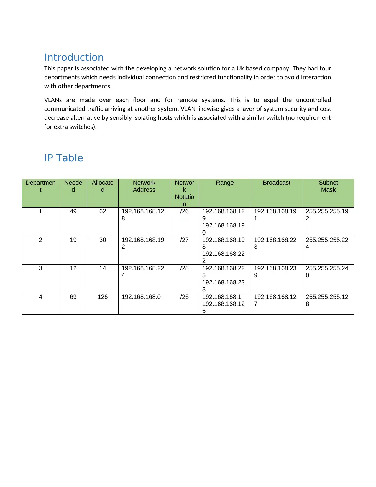
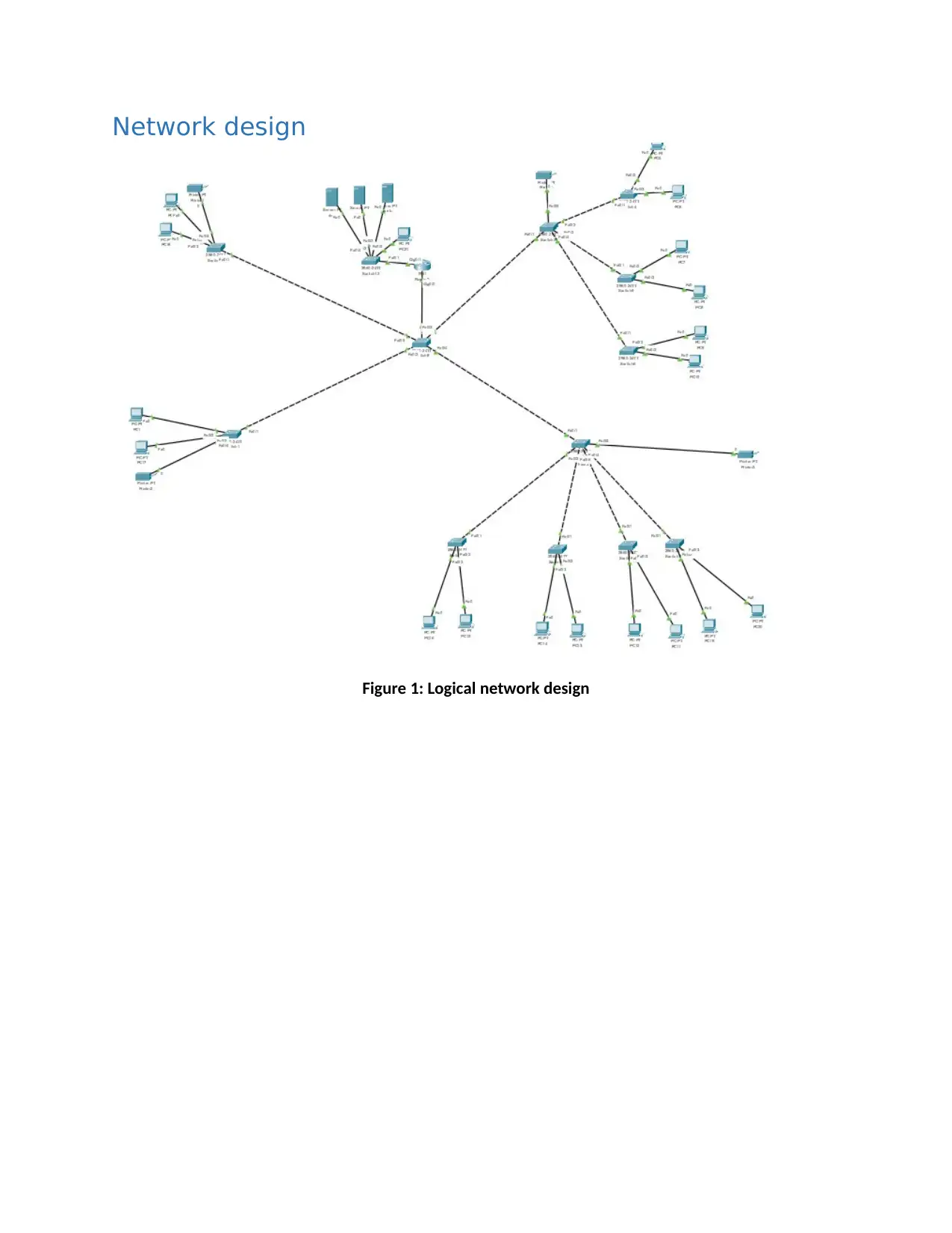
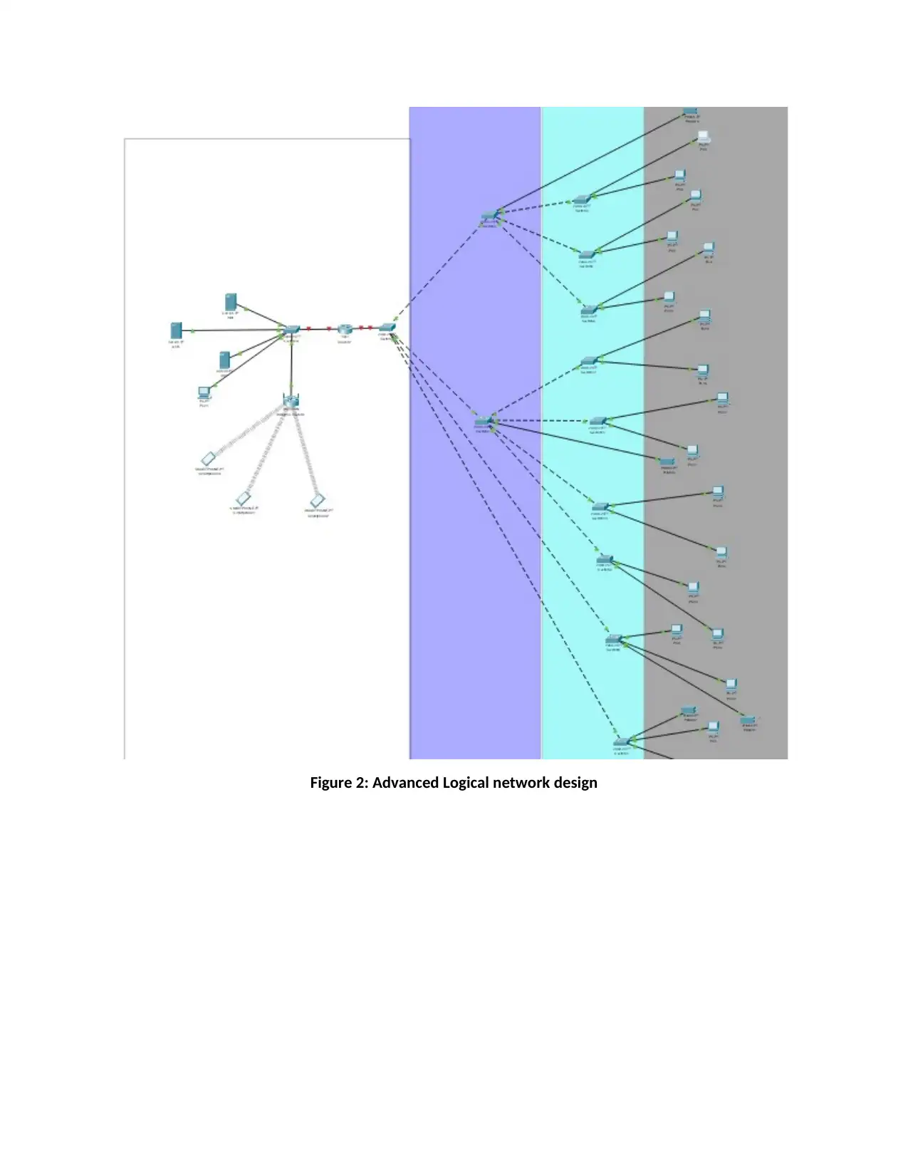
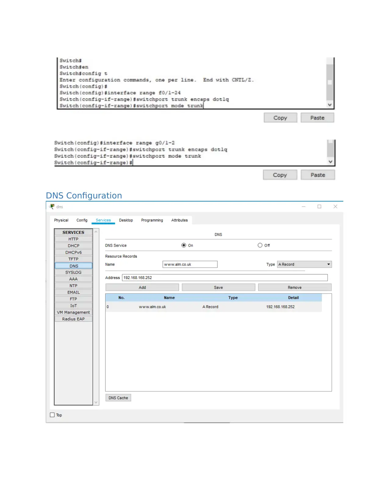
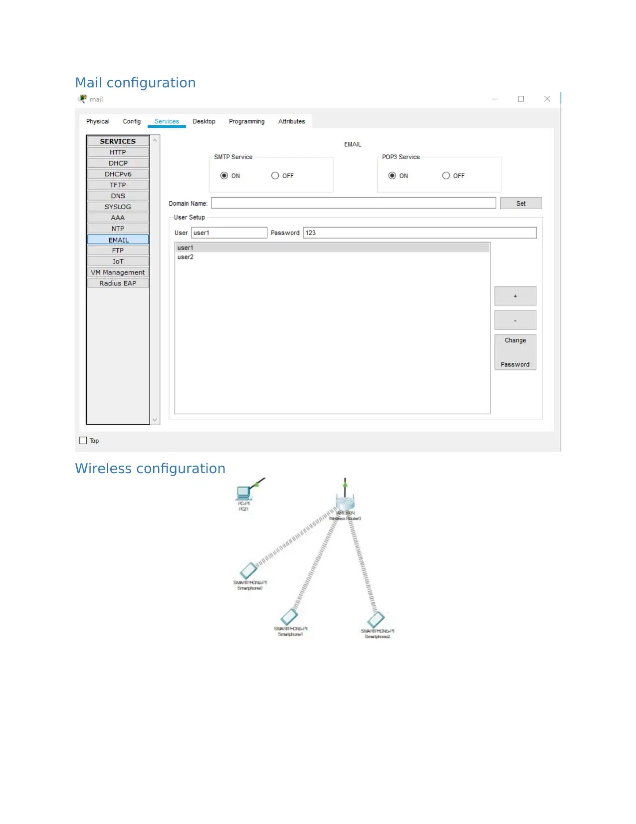
This report details the design and implementation of a network solution for a UK-based company with four departments requiring individual connections and restricted functionality. The solution involves VLANs for each floor and remote systems to isolate traffic and enhance security and cost-effectiveness. The report includes an IP table outlining network addresses and subnet masks for each department, along with logical network designs and configuration details for PCs, routers, VLANs, DNS, mail, and wireless settings. It covers ping tests and descriptions of network components like NICs, switches, and protocols such as routing, DNS, and spanning tree. The report discusses network design principles, including the use of a star topology and LAN characteristics, and concludes with references to relevant literature. The solution utilizes Cisco Packet Tracer for network design and analysis, ensuring scalability, redundancy, performance, security, and practicality. The report also covers subnetting, wireless configurations, and various network protocols.


1 out of 19
Related Documents


Your All-in-One AI-Powered Toolkit for Academic Success.
+13062052269
info@desklib.com
Available 24*7 on WhatsApp / Email
![[object Object]](/_next/static/media/star-bottom.7253800d.svg)
Copyright © 2020–2026 A2Z Services. All Rights Reserved. Developed and managed by ZUCOL.