MN503 Network Design and Configuration Report for Hospitals
VerifiedAdded on 2024/05/15
|16
|1206
|94
Report
AI Summary
This report provides a comprehensive overview of network design and configuration, focusing on upgrading the network infrastructure of Carilion Roanoke Memorial Hospital. It covers the network architecture, hardware and software requirements, and detailed configurations for Cisco switches and routers, including VLAN setup and VTP implementation. The report also addresses troubleshooting steps for common network issues and includes an analysis of the proposed network's ability to handle future growth and traffic load, ensuring high availability and scalability. The document emphasizes the importance of thorough planning and testing before actual implementation to minimize disruptions and ensure optimal performance. Desklib provides this document as a valuable resource for students.
Network Design with
Configuration
Student Name: Priyanka Duggal
1
Configuration
Student Name: Priyanka Duggal
1
Paraphrase This Document
Need a fresh take? Get an instant paraphrase of this document with our AI Paraphraser
Contents
Introduction......................................................................................................................................................3
Network Design................................................................................................................................................4
Requirement.....................................................................................................................................................5
Network Device Configuration.........................................................................................................................6
Switch Configuration....................................................................................................................................6
Router Configuration....................................................................................................................................8
Network Device Configuration.......................................................................................................................11
Switch Configuration..................................................................................................................................11
Router Configuration..................................................................................................................................12
Troubleshooting.............................................................................................................................................14
Analysis...........................................................................................................................................................15
Appendix........................................................................................................................................................16
2
Introduction
Network infrastructure is the important part of the Carilion Roanoke Memorial Hospital and it is needed to
be upgraded in order to fulfil the requirement of the services. And the network must stay up 24x7 without
any interruption. The outage in services may cause serious consequences in the working of the entire
hospital infrastructure.
The proposed network infrastructure will help in providing various services to the medical facilities and the
employees and doctors can take advantage of it. And it will ease the process of work for both the employee
and the client. The overall load on the networking device will be balanced in order to take advantage of the
extra processing power which will reduce the latency and improve the application performance of the
system.
3
⊘ This is a preview!⊘
Do you want full access?
Subscribe today to unlock all pages.

Trusted by 1+ million students worldwide
Network Design
Now the most important thing which comes to the mind and network administrator is the architecture of
the whole project. Because nothing can be implemented without the architectural plan for the network.
Through this, the analyst and engineer can rectify the issues and will save a lot of work before the actual
implementation.
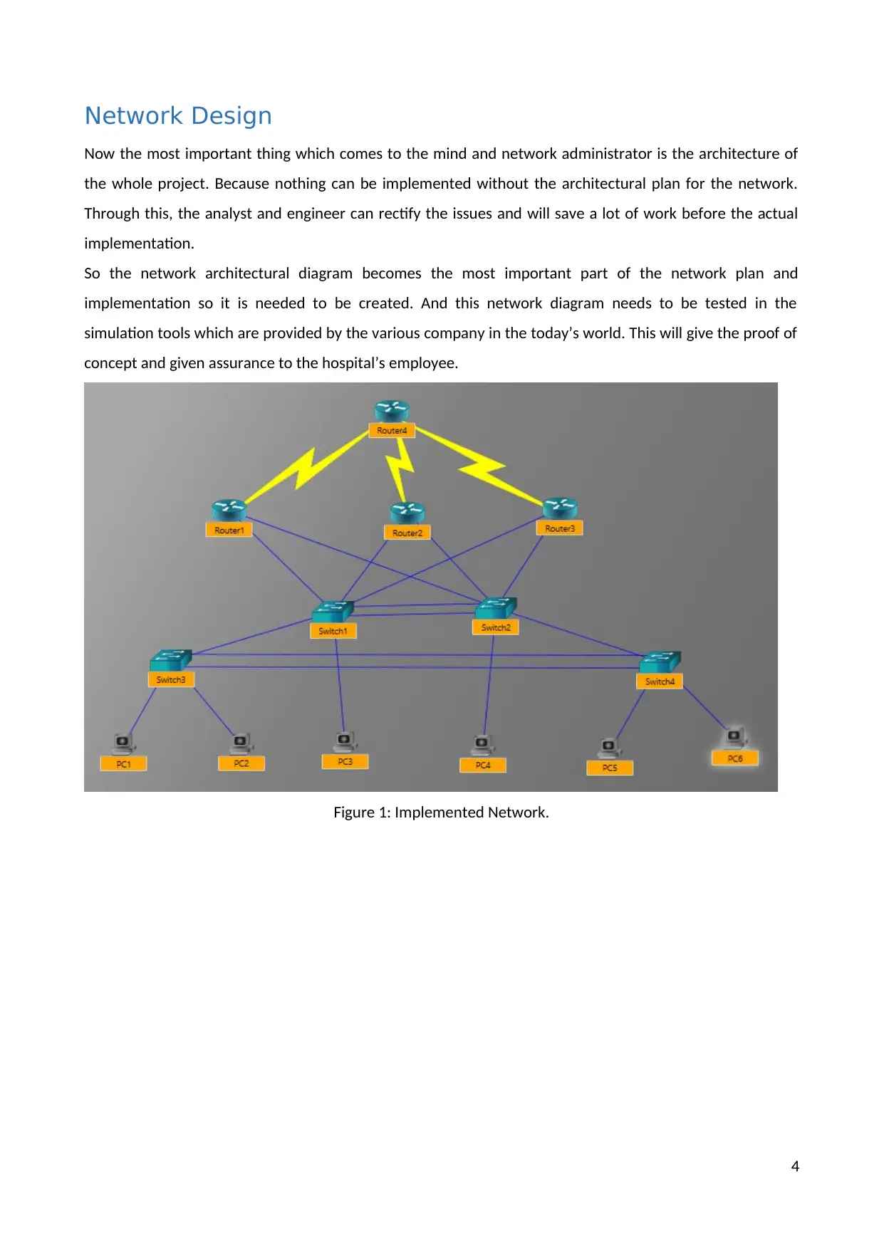
So the network architectural diagram becomes the most important part of the network plan and
implementation so it is needed to be created. And this network diagram needs to be tested in the
simulation tools which are provided by the various company in the today’s world. This will give the proof of
concept and given assurance to the hospital’s employee.
Figure 1: Implemented Network.
4
Paraphrase This Document
Need a fresh take? Get an instant paraphrase of this document with our AI Paraphraser
Requirement
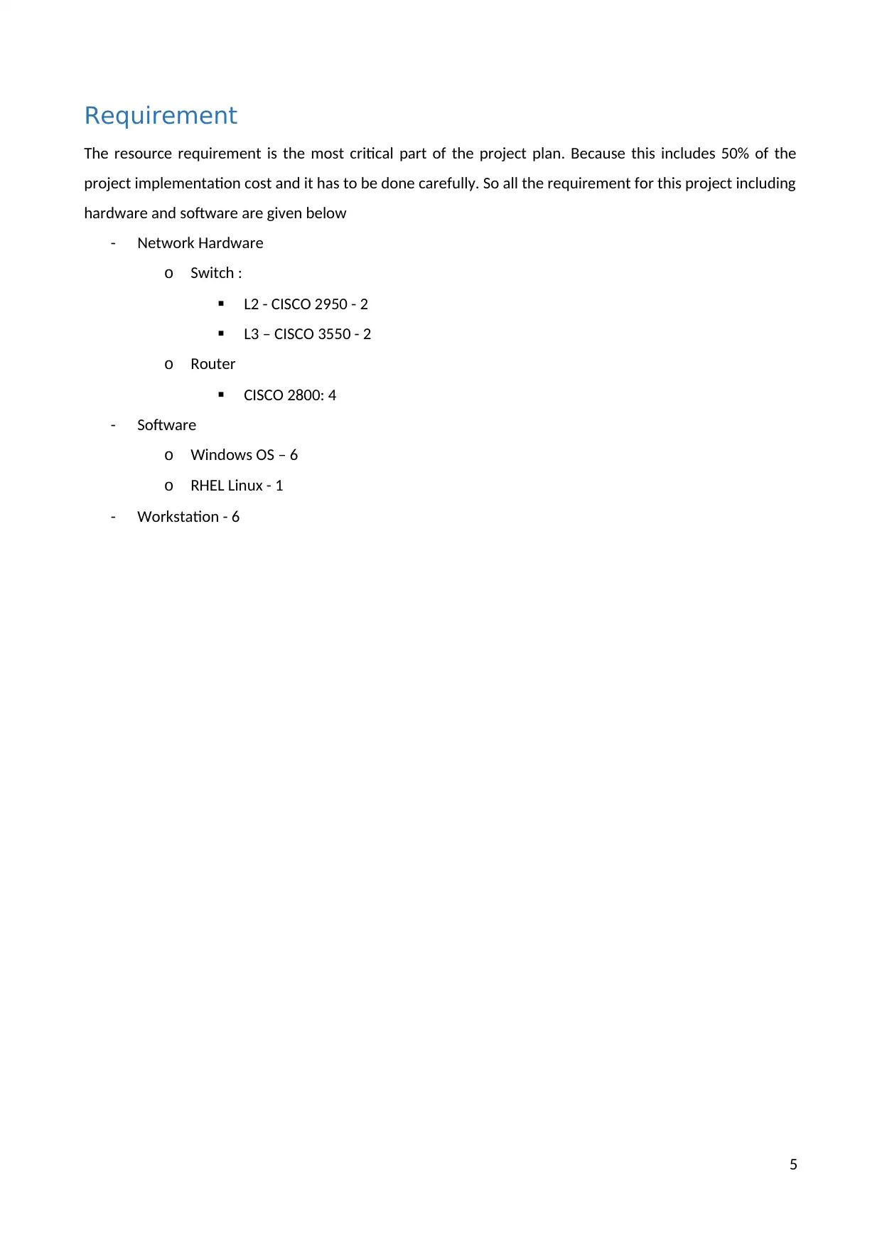
The resource requirement is the most critical part of the project plan. Because this includes 50% of the
project implementation cost and it has to be done carefully. So all the requirement for this project including
hardware and software are given below
- Network Hardware
o Switch :
L2 - CISCO 2950 - 2
L3 – CISCO 3550 - 2
o Router
CISCO 2800: 4
- Software
o Windows OS – 6
o RHEL Linux - 1
- Workstation - 6
5
Network Device Configuration
The configuration of all the hardware and software requirement by the proposed network project needs to
be done and tested before the actual implementation. And this configuration are created before the
implementation of the actual project. And this will help in making sure everything are according to the plan
and tested.
And any issue encounter at the time of testing can be rectified. Thus, the configuration of all the network
devices given below.
Switch Configuration
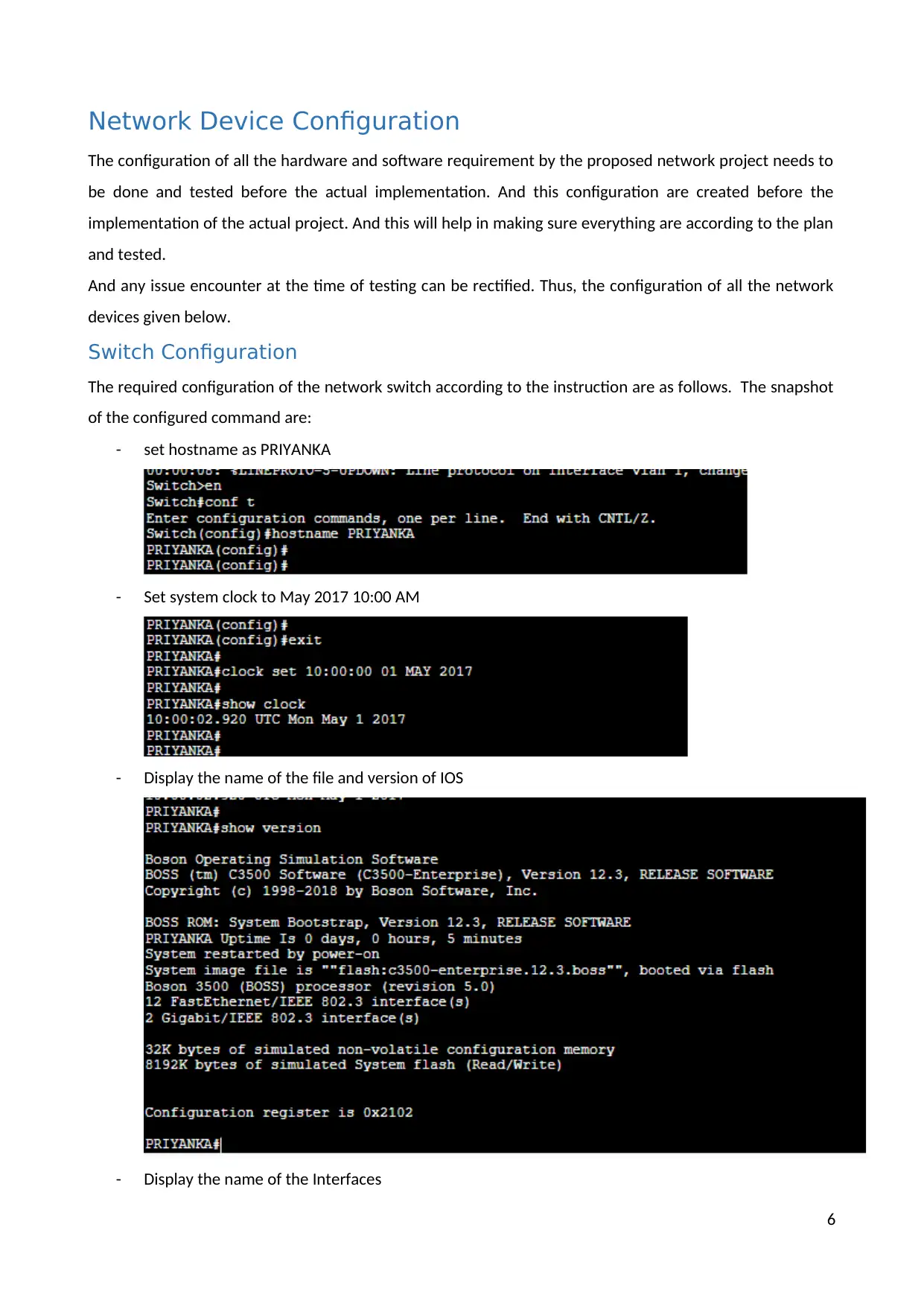
The required configuration of the network switch according to the instruction are as follows. The snapshot
of the configured command are:
- set hostname as PRIYANKA
- Set system clock to May 2017 10:00 AM
- Display the name of the file and version of IOS
- Display the name of the Interfaces
6
⊘ This is a preview!⊘
Do you want full access?
Subscribe today to unlock all pages.

Trusted by 1+ million students worldwide
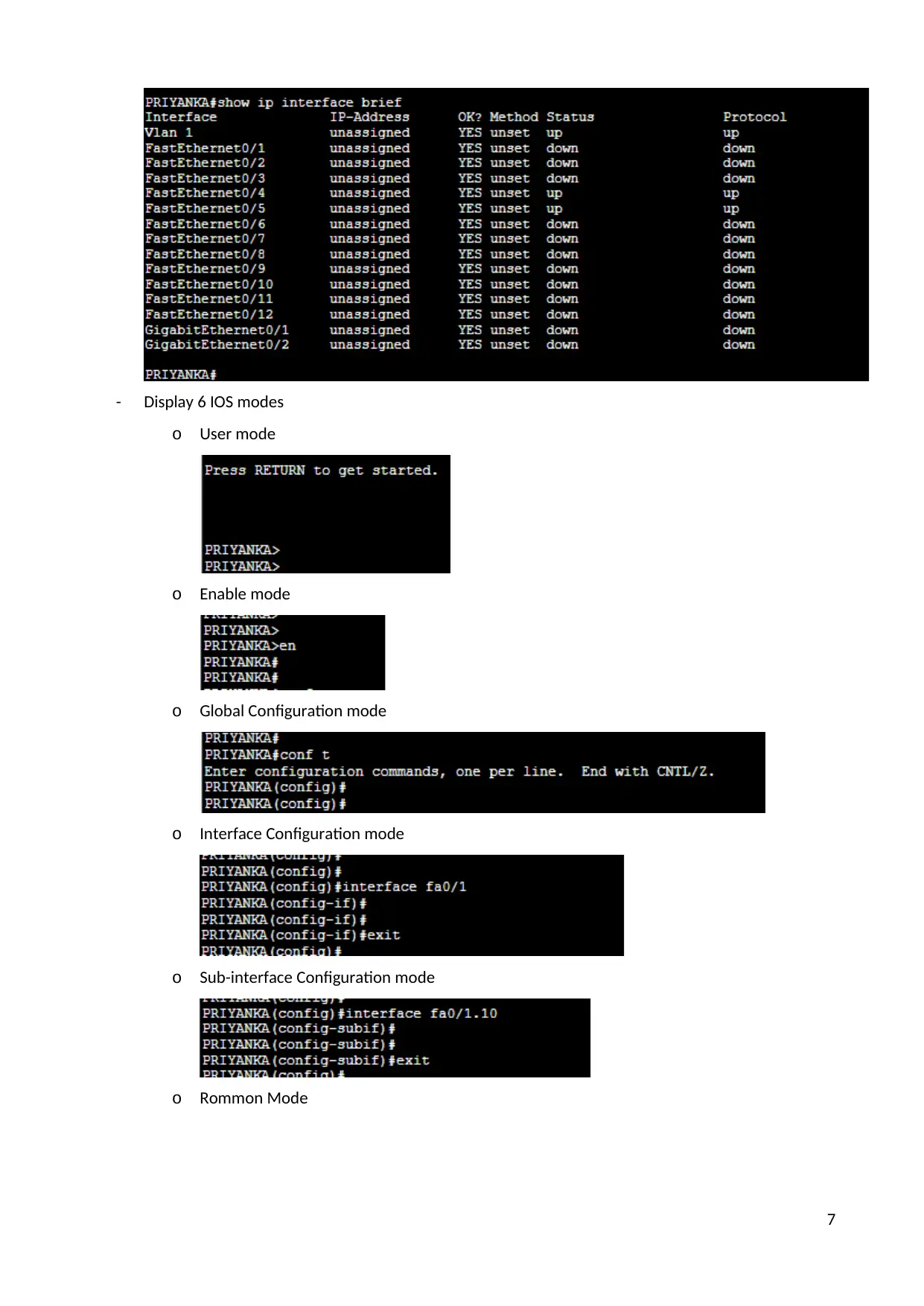
- Display 6 IOS modes
o User mode
o Enable mode
o Global Configuration mode
o Interface Configuration mode
o Sub-interface Configuration mode
o Rommon Mode
7
o User mode
o Enable mode
o Global Configuration mode
o Interface Configuration mode
o Sub-interface Configuration mode
o Rommon Mode
7
Paraphrase This Document
Need a fresh take? Get an instant paraphrase of this document with our AI Paraphraser
Router Configuration
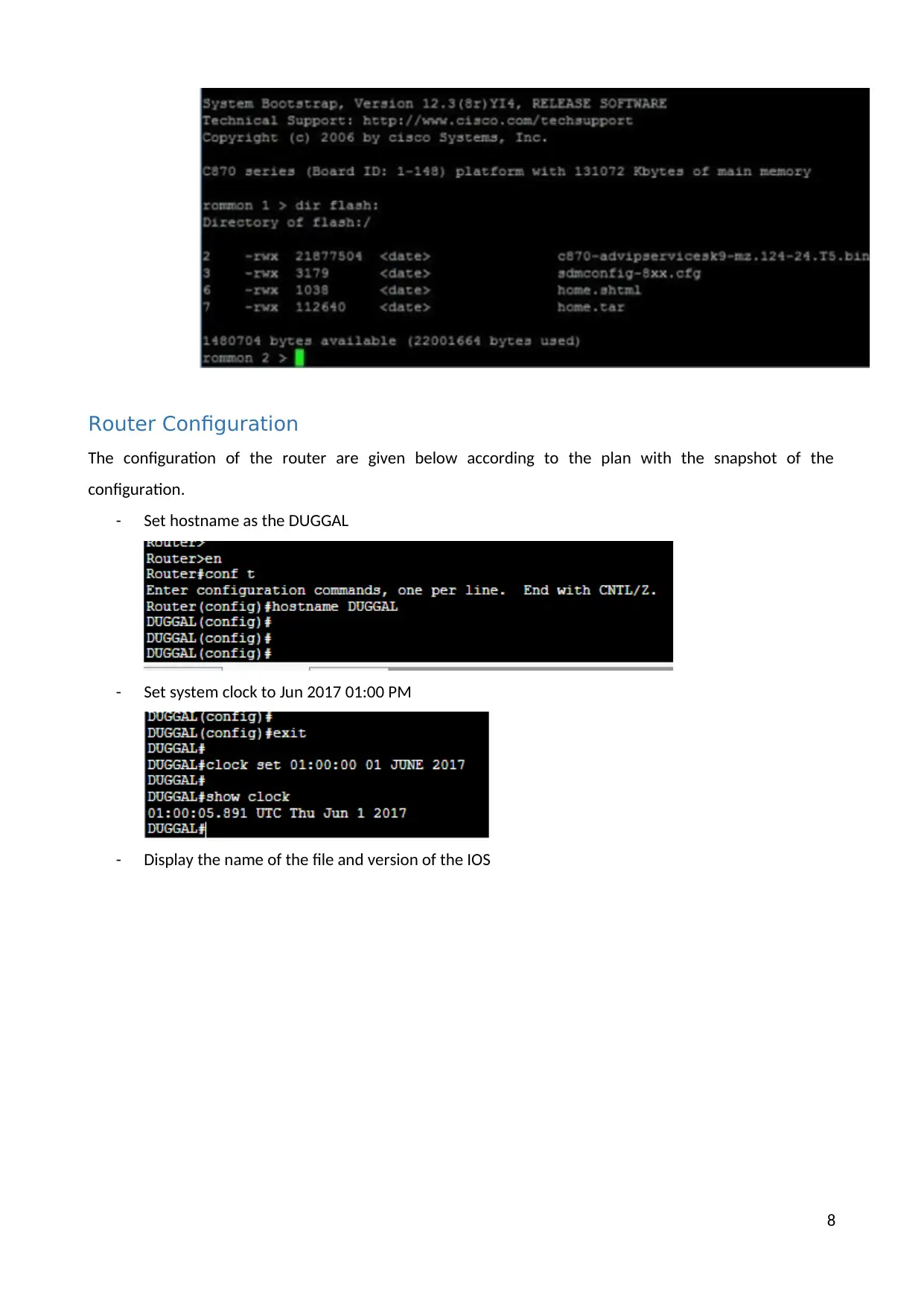
The configuration of the router are given below according to the plan with the snapshot of the
configuration.
- Set hostname as the DUGGAL
- Set system clock to Jun 2017 01:00 PM
- Display the name of the file and version of the IOS
8
The configuration of the router are given below according to the plan with the snapshot of the
configuration.
- Set hostname as the DUGGAL
- Set system clock to Jun 2017 01:00 PM
- Display the name of the file and version of the IOS
8
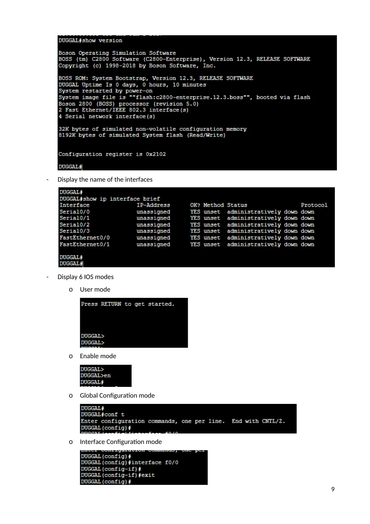
- Display the name of the interfaces
- Display 6 IOS modes
o User mode
o Enable mode
o Global Configuration mode
o Interface Configuration mode
9
- Display 6 IOS modes
o User mode
o Enable mode
o Global Configuration mode
o Interface Configuration mode
9
⊘ This is a preview!⊘
Do you want full access?
Subscribe today to unlock all pages.

Trusted by 1+ million students worldwide
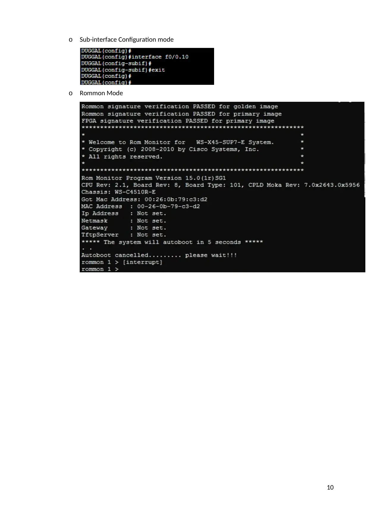
o Sub-interface Configuration mode
o Rommon Mode
10
o Rommon Mode
10
Paraphrase This Document
Need a fresh take? Get an instant paraphrase of this document with our AI Paraphraser
Network Device Configuration
Switch Configuration
Configuration are as follows:
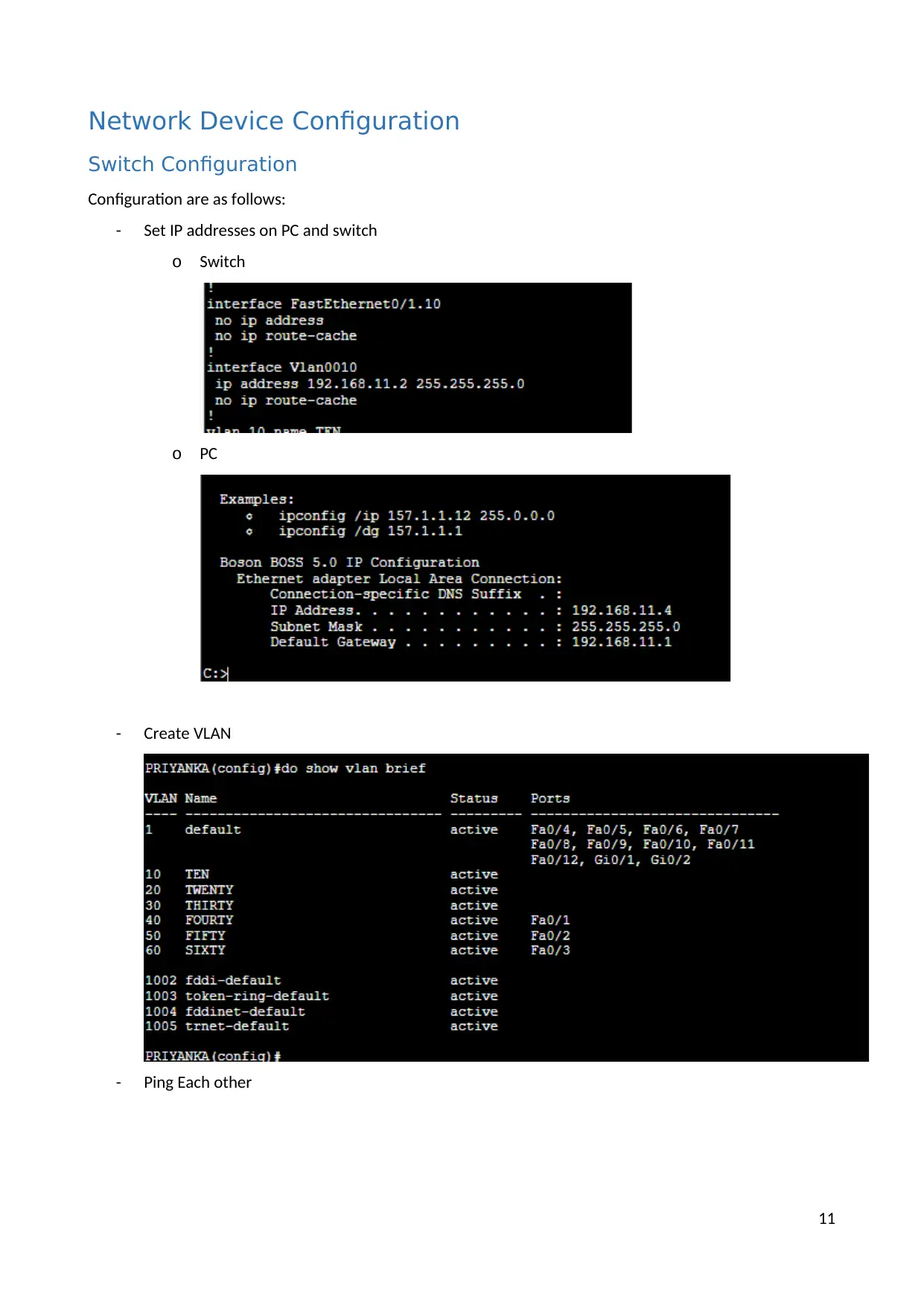
- Set IP addresses on PC and switch
o Switch
o PC
- Create VLAN
- Ping Each other
11
Switch Configuration
Configuration are as follows:
- Set IP addresses on PC and switch
o Switch
o PC
- Create VLAN
- Ping Each other
11
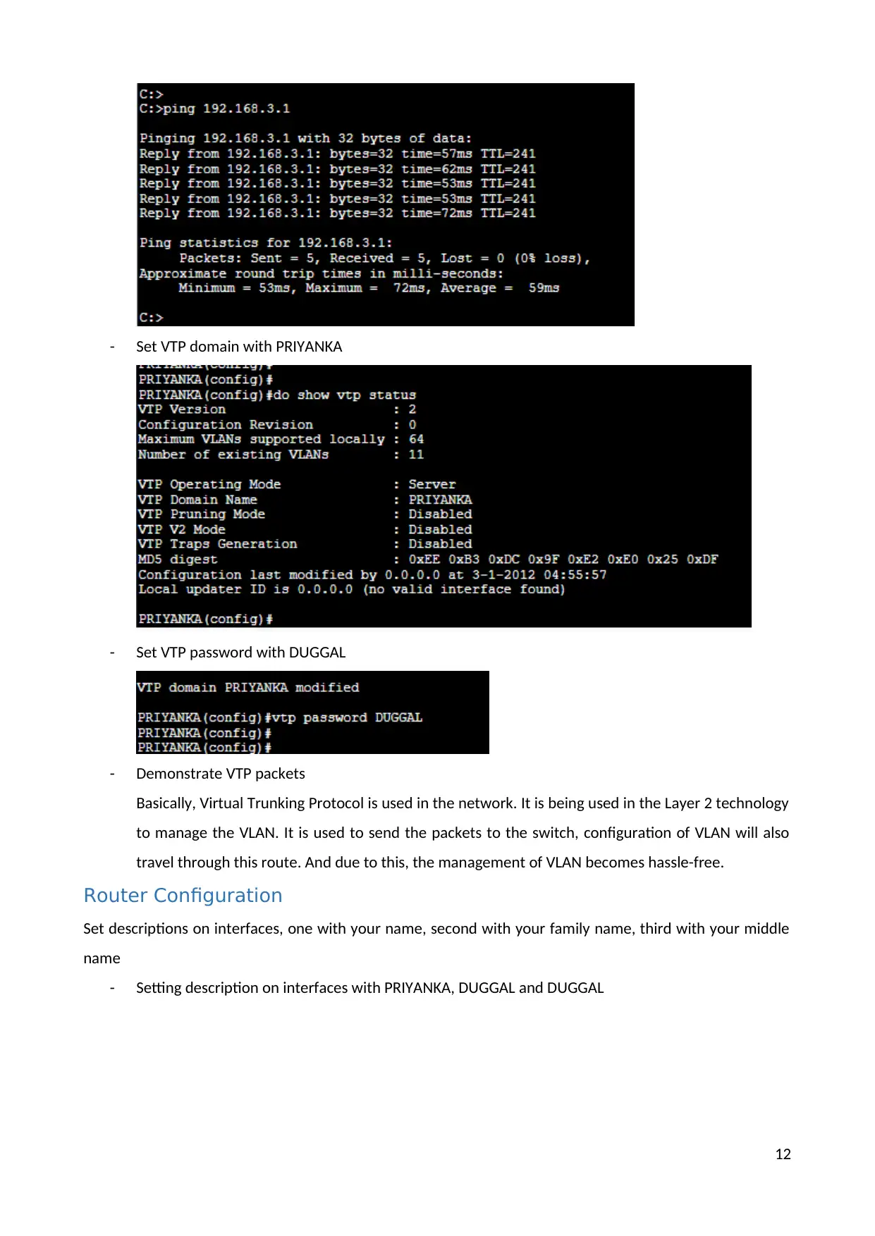
- Set VTP domain with PRIYANKA
- Set VTP password with DUGGAL
- Demonstrate VTP packets
Basically, Virtual Trunking Protocol is used in the network. It is being used in the Layer 2 technology
to manage the VLAN. It is used to send the packets to the switch, configuration of VLAN will also
travel through this route. And due to this, the management of VLAN becomes hassle-free.
Router Configuration
Set descriptions on interfaces, one with your name, second with your family name, third with your middle
name
- Setting description on interfaces with PRIYANKA, DUGGAL and DUGGAL
12
⊘ This is a preview!⊘
Do you want full access?
Subscribe today to unlock all pages.

Trusted by 1+ million students worldwide
1 out of 16
Related Documents
Your All-in-One AI-Powered Toolkit for Academic Success.
+13062052269
info@desklib.com
Available 24*7 on WhatsApp / Email
![[object Object]](/_next/static/media/star-bottom.7253800d.svg)
Unlock your academic potential
Copyright © 2020–2026 A2Z Services. All Rights Reserved. Developed and managed by ZUCOL.


