Local Area Network Design and IP Addressing Plan Presentation
VerifiedAdded on 2023/03/30
|13
|896
|270
Presentation
AI Summary
This presentation outlines a network design and IP addressing plan developed for MyNetworks Company, focusing on an extended star topology to enhance redundancy and eliminate single points of failure. The LAN design incorporates separate switches for each floor or department, with a central switch configured as a VTP server to distribute VLAN information. Two layer 3 switches are used for redundancy. The presentation includes a detailed IP addressing scheme, hardware requirements, and server specifications for email and web services. The design aims to improve network scalability, performance, and provide consistent performance across all user locations, accommodating future growth and expansion of the organization. The document is available on Desklib, a platform providing AI-based study tools for students.

Network Design
Presentation
Name of the Student
Name of the University
Author’s Note
Presentation
Name of the Student
Name of the University
Author’s Note
Paraphrase This Document
Need a fresh take? Get an instant paraphrase of this document with our AI Paraphraser
Introduction
The presentation is prepared for MyNetworks Company for the
development of a local area network design and IP addressing plan.
The building floor plan of the organization and the number of
departments and the location of each of the department is analyzed
for the development of then network design. The application used by
each of the department and the requirement of bandwidth for
increasing the efficiency of the network is estimated such that
response time of the network is reducing and congestion, packet loss
and jitter can also be reducing and thus improving the network
performance.
Network Topology
Extended star network topology is selected for the development of
the network solution for MyNetworks Company. In the basic star
topology, the nodes are connected to a central network hardware
device and it can be hubs/ switch creating a point to point connection
for forming the physical network segment. Here the switch acts as
the server for the computer devices connected to it are entrusted on
it because it is the main point for exchange of information (Moin et al.
2017). It has some negative and positive effects on the network
solution and the extended star topology is used for increasing the
redundancy of the network device and eliminate the dependency on
the central device by creating multiple redundant path for reaching
the destination address in the lo0cal area network.
⊘ This is a preview!⊘
Do you want full access?
Subscribe today to unlock all pages.

Trusted by 1+ million students worldwide
LAN Design
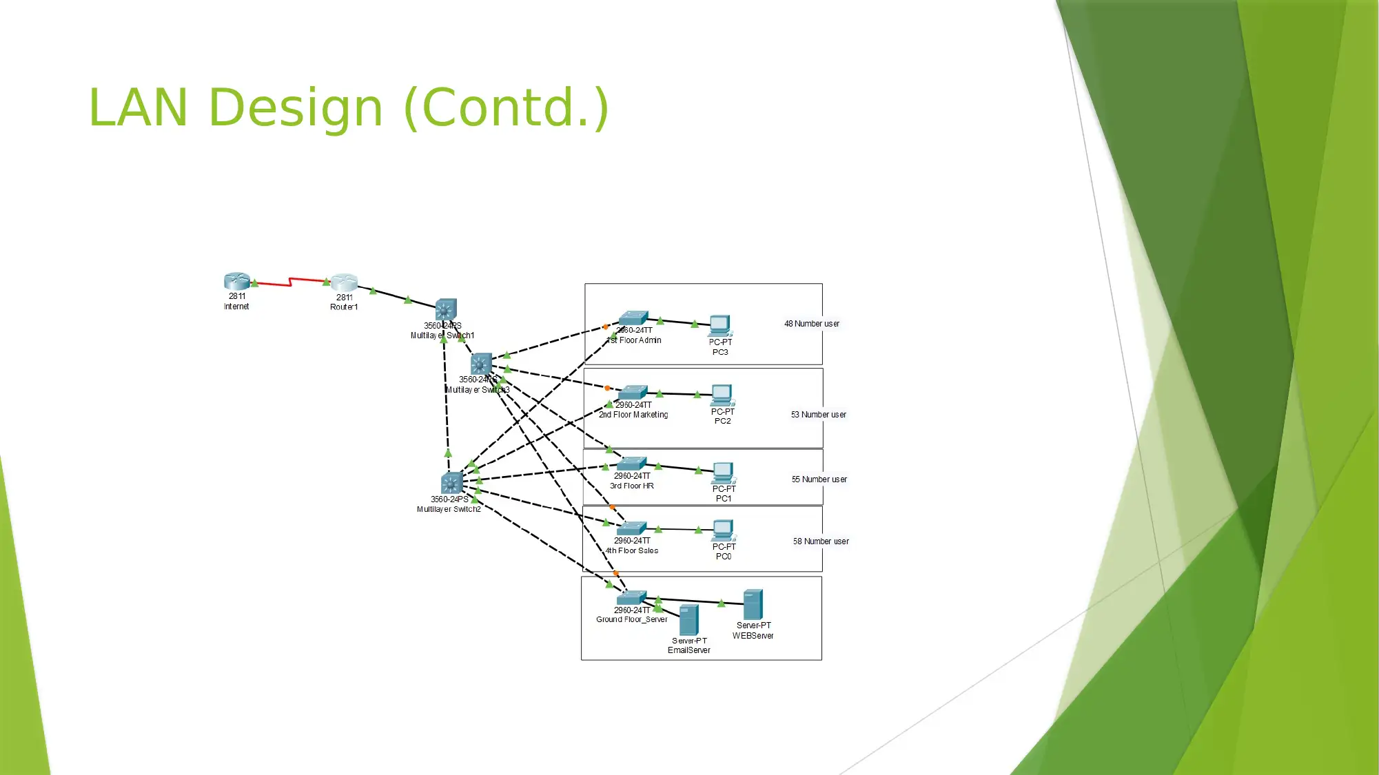
The local area network design is created after analyzing the building
floor plan of the company and for each of the floor or the department
a separate switch is used. The central switch connected with the
router interface is configured as VTP server and the VLANs are
configured in the switch. The other switches are configured as VTP
client such that the VLAN information are automatically distributed to
each of the network device. The two layer 3 switch are used for
increasing the redundancy and eliminating the risk of failure of single
device.
Paraphrase This Document
Need a fresh take? Get an instant paraphrase of this document with our AI Paraphraser
LAN Design (Contd.)
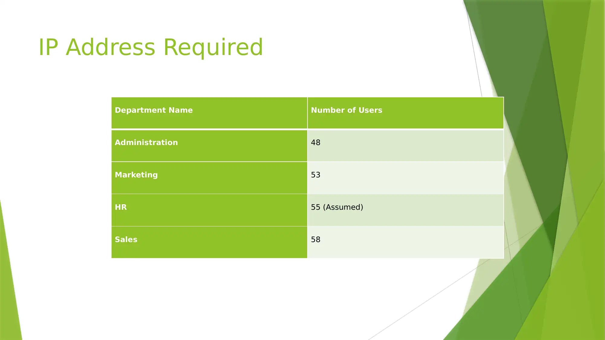
IP Address Required
Department Name Number of Users
Administration 48
Marketing 53
HR 55 (Assumed)
Sales 58
Department Name Number of Users
Administration 48
Marketing 53
HR 55 (Assumed)
Sales 58
⊘ This is a preview!⊘
Do you want full access?
Subscribe today to unlock all pages.

Trusted by 1+ million students worldwide
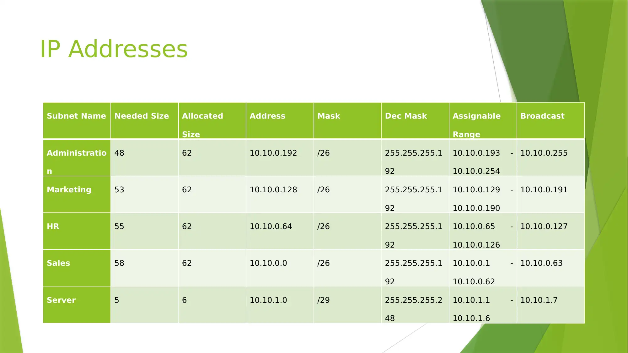
IP Addresses
Subnet Name Needed Size Allocated
Size
Address Mask Dec Mask Assignable
Range
Broadcast
Administratio
n
48 62 10.10.0.192 /26 255.255.255.1
92
10.10.0.193 -
10.10.0.254
10.10.0.255
Marketing 53 62 10.10.0.128 /26 255.255.255.1
92
10.10.0.129 -
10.10.0.190
10.10.0.191
HR 55 62 10.10.0.64 /26 255.255.255.1
92
10.10.0.65 -
10.10.0.126
10.10.0.127
Sales 58 62 10.10.0.0 /26 255.255.255.1
92
10.10.0.1 -
10.10.0.62
10.10.0.63
Server 5 6 10.10.1.0 /29 255.255.255.2
48
10.10.1.1 -
10.10.1.6
10.10.1.7
Paraphrase This Document
Need a fresh take? Get an instant paraphrase of this document with our AI Paraphraser
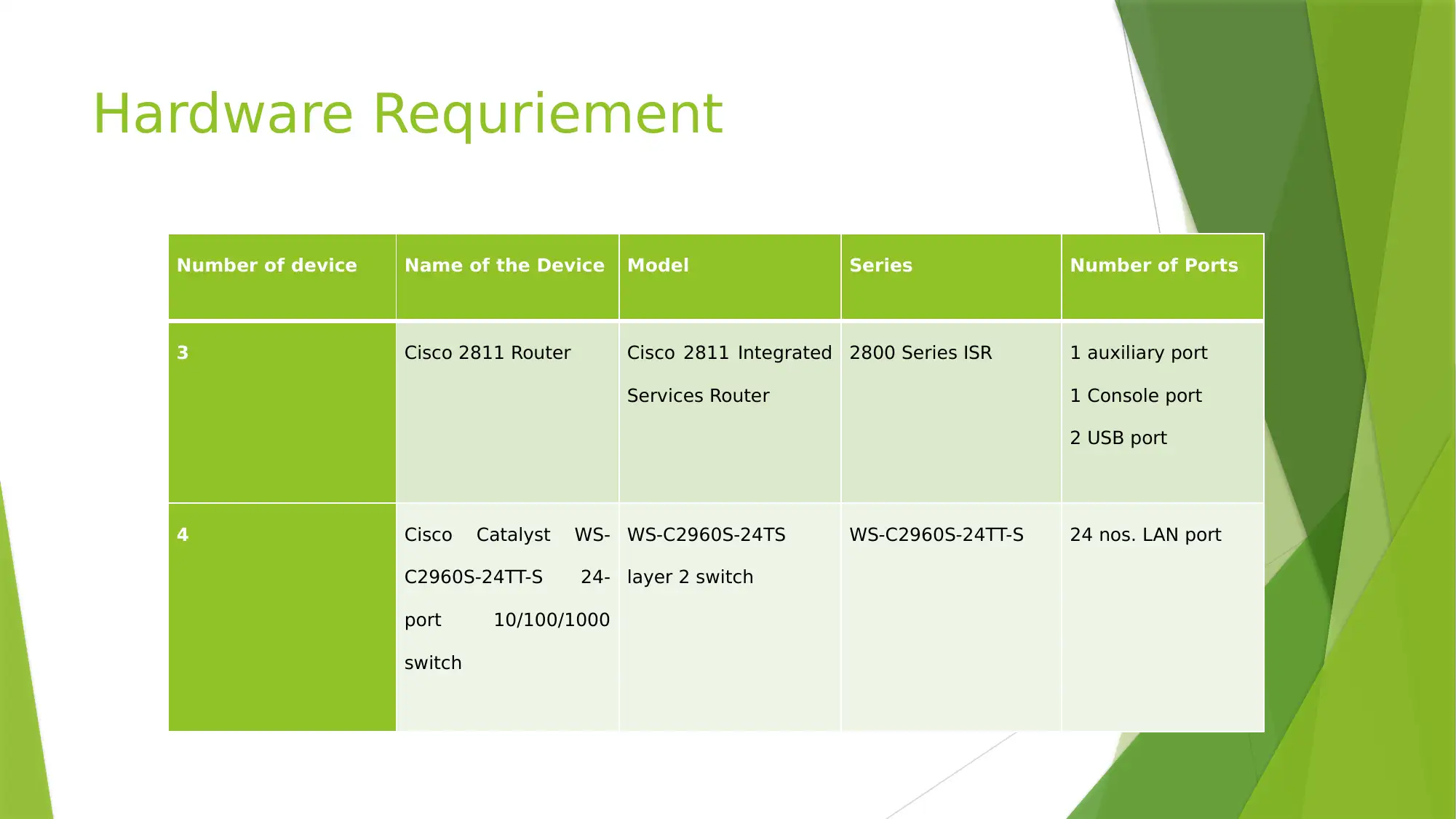
Hardware Requriement
Number of device Name of the Device Model Series Number of Ports
3 Cisco 2811 Router Cisco 2811 Integrated
Services Router
2800 Series ISR 1 auxiliary port
1 Console port
2 USB port
4 Cisco Catalyst WS-
C2960S-24TT-S 24-
port 10/100/1000
switch
WS-C2960S-24TS
layer 2 switch
WS-C2960S-24TT-S 24 nos. LAN port
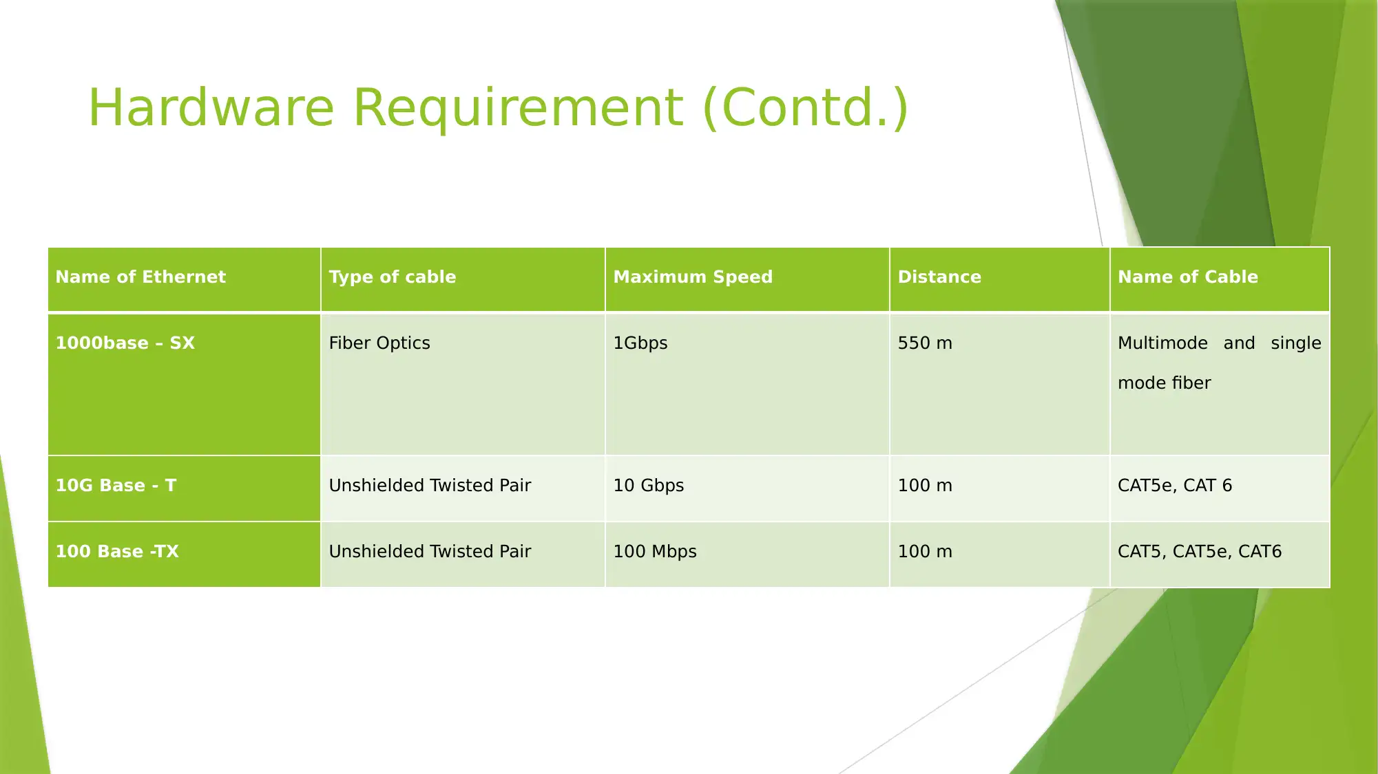
Hardware Requirement (Contd.)
Name of Ethernet Type of cable Maximum Speed Distance Name of Cable
1000base – SX Fiber Optics 1Gbps 550 m Multimode and single
mode fiber
10G Base - T Unshielded Twisted Pair 10 Gbps 100 m CAT5e, CAT 6
100 Base -TX Unshielded Twisted Pair 100 Mbps 100 m CAT5, CAT5e, CAT6
Name of Ethernet Type of cable Maximum Speed Distance Name of Cable
1000base – SX Fiber Optics 1Gbps 550 m Multimode and single
mode fiber
10G Base - T Unshielded Twisted Pair 10 Gbps 100 m CAT5e, CAT 6
100 Base -TX Unshielded Twisted Pair 100 Mbps 100 m CAT5, CAT5e, CAT6
⊘ This is a preview!⊘
Do you want full access?
Subscribe today to unlock all pages.

Trusted by 1+ million students worldwide
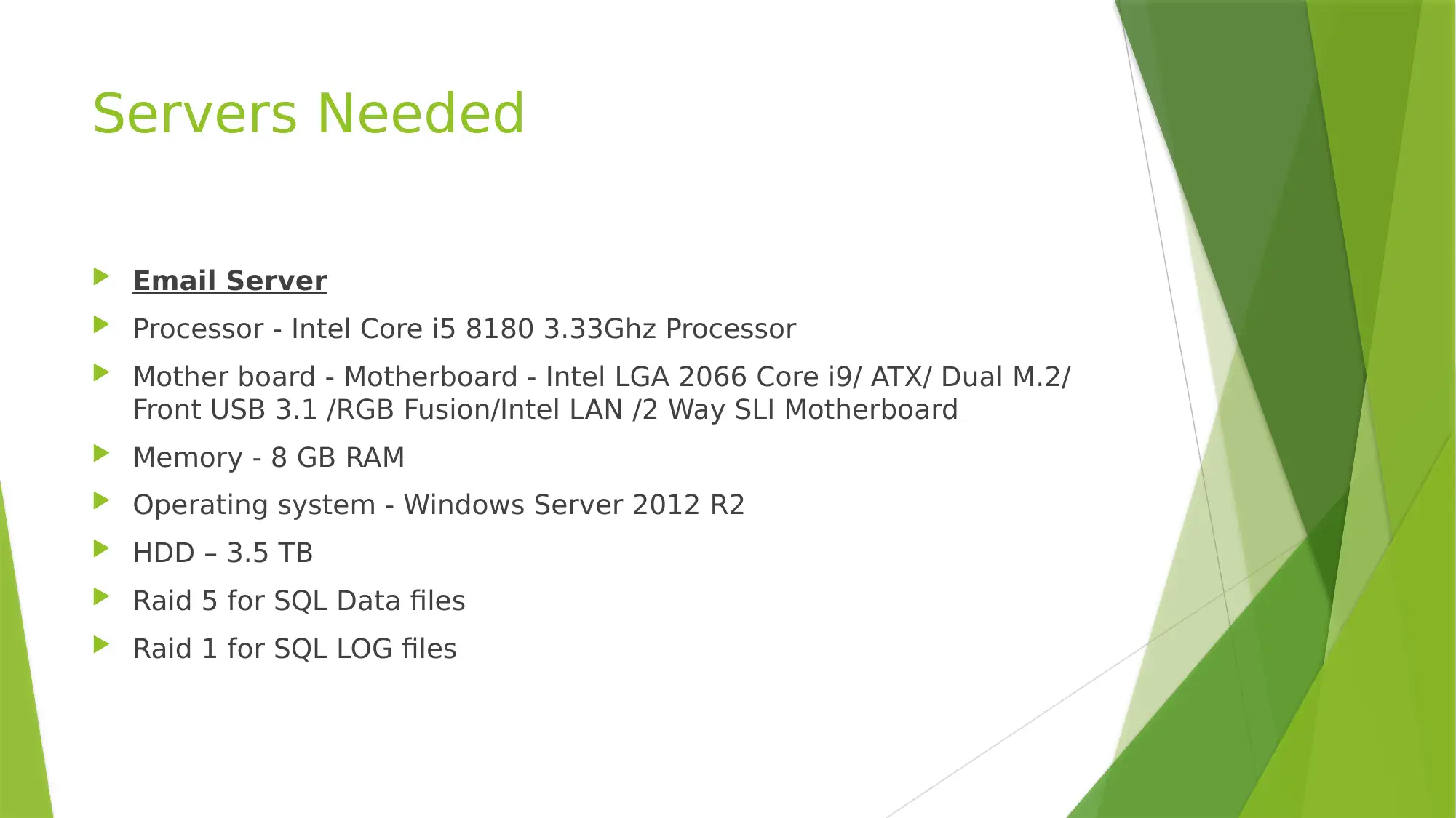
Servers Needed
Email Server
Processor - Intel Core i5 8180 3.33Ghz Processor
Mother board - Motherboard - Intel LGA 2066 Core i9/ ATX/ Dual M.2/
Front USB 3.1 /RGB Fusion/Intel LAN /2 Way SLI Motherboard
Memory - 8 GB RAM
Operating system - Windows Server 2012 R2
HDD – 3.5 TB
Raid 5 for SQL Data files
Raid 1 for SQL LOG files
Paraphrase This Document
Need a fresh take? Get an instant paraphrase of this document with our AI Paraphraser

Servers Needed
WEB Server
Processor - Intel 3.3GHz LGA 1155 Core i7 8180 Processor
Memory - 8 GB RAM
Motherboard - Intel LGA 2066 Core i9/ ATX/ Dual M.2/ Front USB 3.1
/RGB Fusion/Intel LAN /2 Way SLI Motherboard
Operating System - Windows server 2012 R2 64 bits
HDD – 2 TB
Raid 5 for SQL Data files
Raid 1 for SQL LOG files
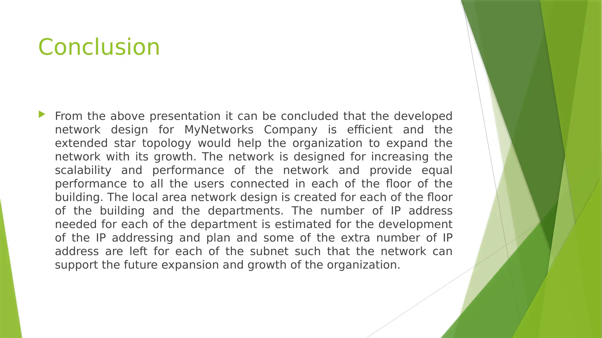
Conclusion
From the above presentation it can be concluded that the developed
network design for MyNetworks Company is efficient and the
extended star topology would help the organization to expand the
network with its growth. The network is designed for increasing the
scalability and performance of the network and provide equal
performance to all the users connected in each of the floor of the
building. The local area network design is created for each of the floor
of the building and the departments. The number of IP address
needed for each of the department is estimated for the development
of the IP addressing and plan and some of the extra number of IP
address are left for each of the subnet such that the network can
support the future expansion and growth of the organization.
⊘ This is a preview!⊘
Do you want full access?
Subscribe today to unlock all pages.

Trusted by 1+ million students worldwide
1 out of 13
Related Documents
Your All-in-One AI-Powered Toolkit for Academic Success.
+13062052269
info@desklib.com
Available 24*7 on WhatsApp / Email
![[object Object]](/_next/static/media/star-bottom.7253800d.svg)
Unlock your academic potential
Copyright © 2020–2026 A2Z Services. All Rights Reserved. Developed and managed by ZUCOL.


