SBM4104 IT Infrastructure: Network Design Proposal for UOW, 2018
VerifiedAdded on 2023/06/09
|16
|3734
|346
Report
AI Summary
This report proposes an IT infrastructure for the University of Wollongong, Australia, focusing on a secure and modern network to aid daily operations. It outlines project objectives, including flexibility, IP address management, high-speed processing, and network security. The proposed infrastructure includes wired and wireless network media, utilizing fiber and CAT 6a cables, and a three-layer hierarchical model (core, distribution, and access layers) for easier troubleshooting and management. The report details connection devices, such as CISCO routers and switches, and justifies their selection based on business needs and scalability. It also covers logical network topology, subnetting, and a cloud-based design proposal, recommending Microsoft Azure and Google Cloud for virtualization and data storage. The document emphasizes virtualization techniques for creating virtual devices and infrastructures.
Running head: IT INFRASTRUCTURE 1
A Network Design Proposal for the University of Wollongong
Student
Institutional Affiliations
Tutor
Date
A Network Design Proposal for the University of Wollongong
Student
Institutional Affiliations
Tutor
Date
Paraphrase This Document
Need a fresh take? Get an instant paraphrase of this document with our AI Paraphraser
IT INFRASTRUCTURE 2
A Network Design Proposal for the University of Wollongong
1. Introduction
All organizations are focused on the effectiveness and efficiency in their daily activities.
As such, for the business of the organizations to be efficacious, the organization must adopt the
usage of new technology. It is therefore notable that modern technology has been beneficial in
corporations. The advanced technology has made significant changes in the manner in which
activities are conducted therefore reducing workload in offices. As a result, this report proposes
information technology IT infrastructure to the University of Wollongong, Australia. The
University of Wollongong is a public research institution located in New South Wales coastal
region. It has an international network of campuses and a regional learning center as well. Its
parochial schools situated in New South Wales include Bega, Southern Sydney, Batemans Bay,
Southern Highlands and Shoalhaven.
With the expansion of the network campuses of the organization, it is essential to establish
a new network topology to facilitate the operation of the institution. The network must maintain
reliable connectivity throughout the whole campus and maintain security by segregating the data
between institution staffs and students.
2. Project objectives
The primary goals of the project will be to come up with a secured modern network that
will aid in day to day business of the University. The system must be able to perform the
following functionalities:
a. Must be flexible to meet the requirements of the organization
IT INFRASTRUCTURE 3
b. Enable IP address management.
c. Process information and respond at high speed.
d. Provide network security to ensure safety for the organization’s data.
3. IT infrastructure components
3.1. Network media (wired network for PC connections and wireless network for library
and hallways)
There will be connections in the school administration, library, faculty offices,
laboratories, and student center. The network will use fiber as the means of transportation to the
switches closets in administration, faculty offices, laboratories, and library. The connections in
the remaining places will be made through CAT 6a to cut down the installation cost.
3.1.1. Business needs
The organization needs proper IT infrastructures to get connected to the outside internet
enabling students and staffs to utilize the resources on the web at a reasonable speed without
worrying about losing data, internet connection, security threats and being able to connect from
any computer within the campus.
3.1.2. Justifications
The fibers will increase the required speed and ensure the security of specific access
points. Using the CAT 6a will ensure that the internet speed is not degraded and save the
installation cost.
4. The three layer hierarchal model
⊘ This is a preview!⊘
Do you want full access?
Subscribe today to unlock all pages.
Trusted by 1+ million students worldwide
IT INFRASTRUCTURE 4
Various organizations prefer flat network topology; it is easy to design and implement
provided the network covers a small area (Becker, Klein & Wetzels, 2012). However, for more
prominent institutions like the University of Wollongong, the extended system would be
undesirable. As a result, this report proposes the three-layer hierarchical model for the project.
The hierarchical model makes troubleshooting easier compared to other models because instead
of concentrating the troubleshooting efforts in one region of a network, it would be desirable to
inspect the whole system and the hierarchical model would aid in such circumstances (Lin,
2010).
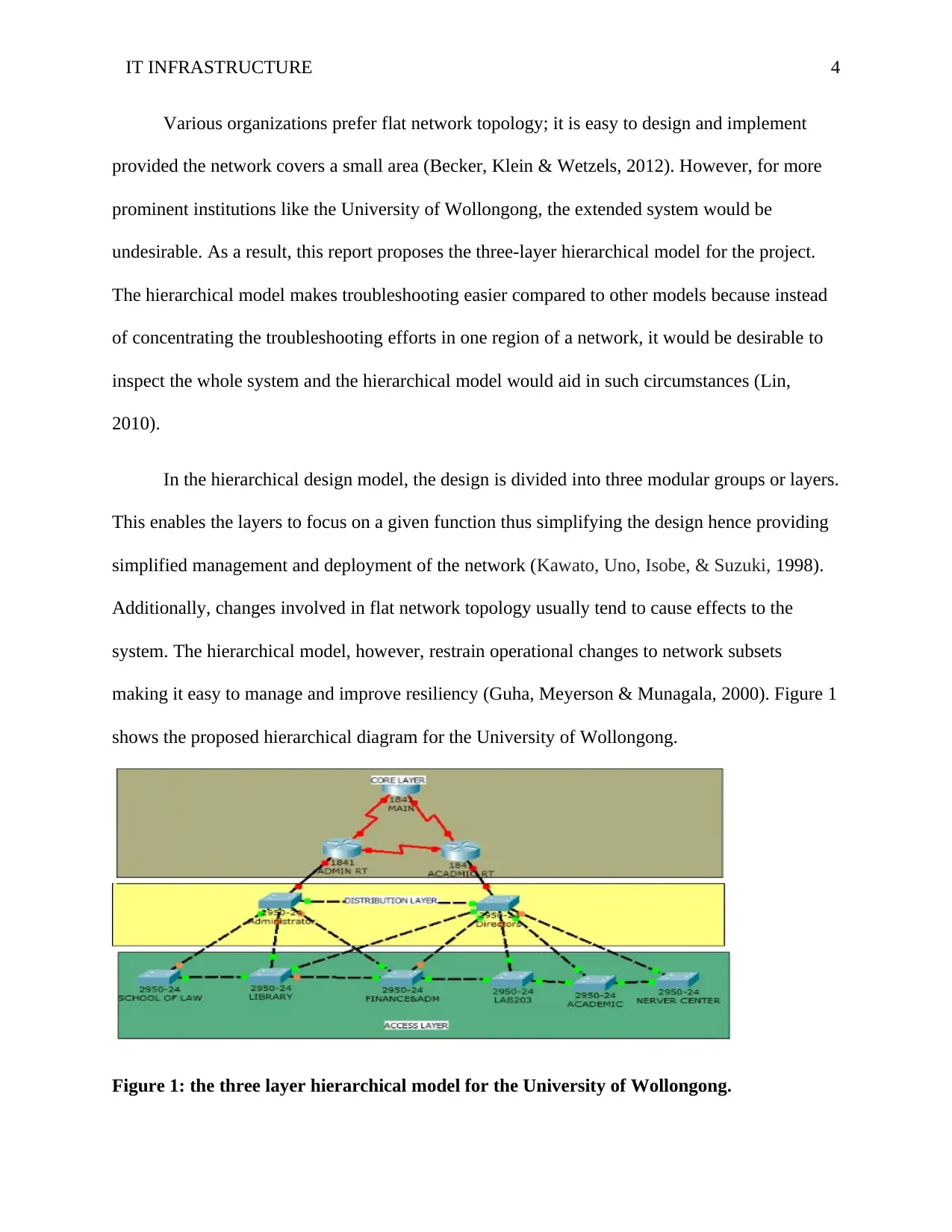
In the hierarchical design model, the design is divided into three modular groups or layers.
This enables the layers to focus on a given function thus simplifying the design hence providing
simplified management and deployment of the network (Kawato, Uno, Isobe, & Suzuki, 1998).
Additionally, changes involved in flat network topology usually tend to cause effects to the
system. The hierarchical model, however, restrain operational changes to network subsets
making it easy to manage and improve resiliency (Guha, Meyerson & Munagala, 2000). Figure 1
shows the proposed hierarchical diagram for the University of Wollongong.
Figure 1: the three layer hierarchical model for the University of Wollongong.
Various organizations prefer flat network topology; it is easy to design and implement
provided the network covers a small area (Becker, Klein & Wetzels, 2012). However, for more
prominent institutions like the University of Wollongong, the extended system would be
undesirable. As a result, this report proposes the three-layer hierarchical model for the project.
The hierarchical model makes troubleshooting easier compared to other models because instead
of concentrating the troubleshooting efforts in one region of a network, it would be desirable to
inspect the whole system and the hierarchical model would aid in such circumstances (Lin,
2010).
In the hierarchical design model, the design is divided into three modular groups or layers.
This enables the layers to focus on a given function thus simplifying the design hence providing
simplified management and deployment of the network (Kawato, Uno, Isobe, & Suzuki, 1998).
Additionally, changes involved in flat network topology usually tend to cause effects to the
system. The hierarchical model, however, restrain operational changes to network subsets
making it easy to manage and improve resiliency (Guha, Meyerson & Munagala, 2000). Figure 1
shows the proposed hierarchical diagram for the University of Wollongong.
Figure 1: the three layer hierarchical model for the University of Wollongong.
Paraphrase This Document
Need a fresh take? Get an instant paraphrase of this document with our AI Paraphraser
IT INFRASTRUCTURE 5
The hierarchical model is consist of the following three layers (Guha et al. 2000).
a. The Core layer: Through this layer, the connections between the distribution layers of
sizeable local area networks LAN environments are made. The core layer reduces network
complexity in the case where the switches of distribution layers are nearby.
b. The Distribution layer: This layer aggregates the access layer and offers connectivity to
services within the campus. The distribution layer also offers connectivity in networks where
connectivity traverses from end to end of a local area network.
c. Access layer: This is where user access devices are linked to the network. This allows
user/workgroup access to the system. The layer offers wired as well as wireless connectivity with
security services thus ensuring security for the entire network.
4.1. Connection devices
4.1.1. Business needs
The campus has four computer labs that are used for teaching computer courses. Every
computer lab will house a closet and 32 devices including 30 student computers, one server, and
one instructor computer for instructional purposes. Students will be expected to consider high
traffic areas for the Wi-Fi-like student center and other sitting areas and not computer labs. The
student center and the other access points which are preserved for high traffic areas can
accommodate up to 250 hosts with two servers.
Additionally, a separate computer lab that will offer computer services to students will be
required. The lab will house one server and 40 computers in a closet for accessing library
IT INFRASTRUCTURE 6
resources, one server and 15 machines will be allocated to the library also, 10 computers for
public use and the remaining 5 for staffs in the library.
Lastly, the campus has offices. 50 computers will be accommodated in the organization’s
faculty offices for staff except for the administration office which will have 10 computers. Four
rooms will be dedicated for servers, one room will be within the administration block, and the
other three rooms will be assigned for various faculty offices.
4.1.2. Proposed network devices
Apart from the initially mentioned devices, CISCO 3925 is recommended for two main
routers and the main switch for the faculty offices. I propose CISCO SG550XG-24F for the
administration block’s main switch and CISCO SG 550X-48P switches for computer lab and
library.
4.1.3. Justification
In high speed (350 Mbps) wireless network, the CISCO 3925 will sustain a deployment.
CISCO SG550XG-24F, however, will continue with the speed from support fibers and routers.
CISCO SG 550X-48P, on the other hand, enables the need for expansion of CPs in the computer
lab and library and even extension to a VoIP system since they get powered over Ethernet cables
instead of buying power supplies for the VoIP phones, thus reducing the installation cost.
4.2. Logical network topology
Logical network topology will be the priority in the logical design phase. For the system to
satisfy its users’ needs of adaptability and scalability, it is essential that a logical topology is
designed before selecting the required network devices (Angskun, Bosilca, & Dongarra, 2007).
⊘ This is a preview!⊘
Do you want full access?
Subscribe today to unlock all pages.
Trusted by 1+ million students worldwide
IT INFRASTRUCTURE 7
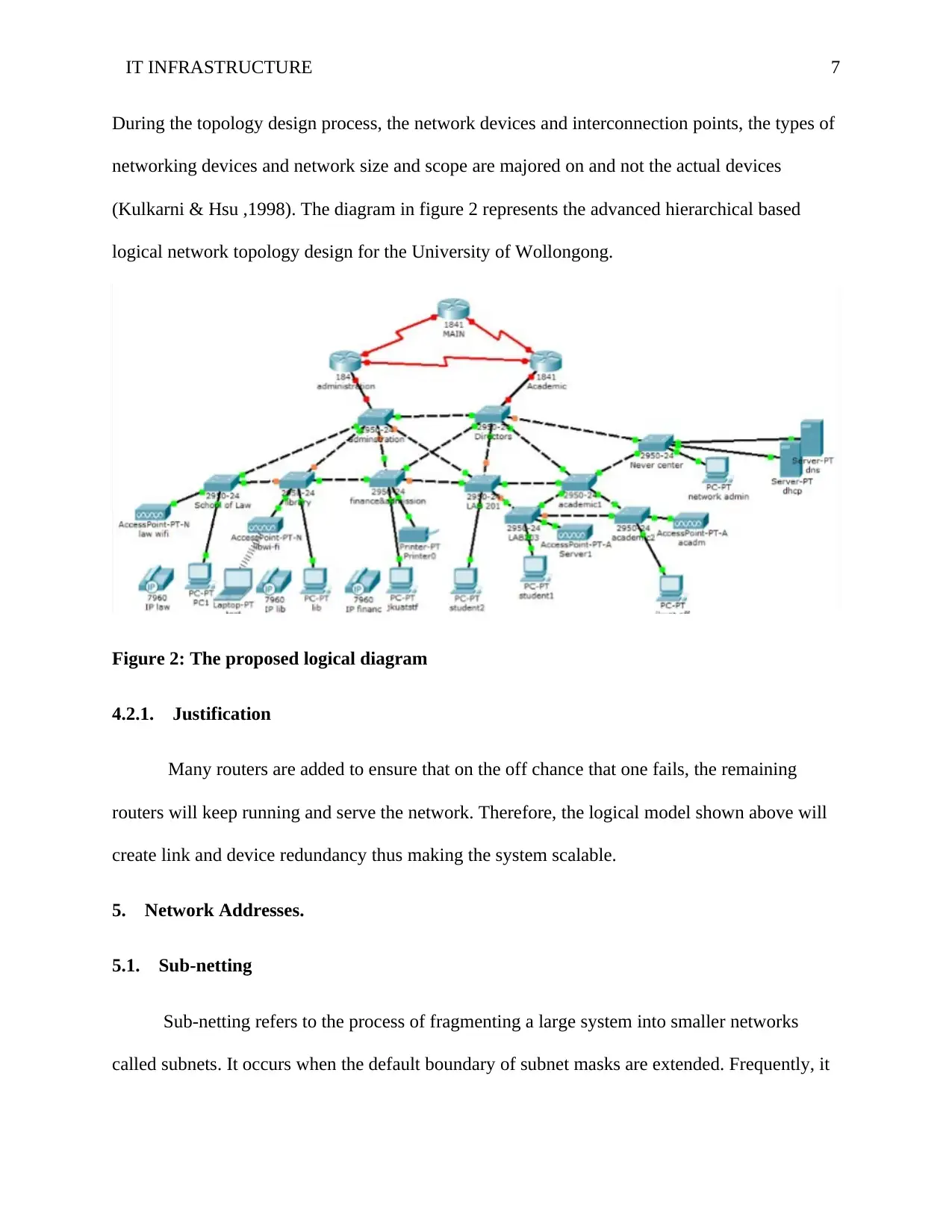
During the topology design process, the network devices and interconnection points, the types of
networking devices and network size and scope are majored on and not the actual devices
(Kulkarni & Hsu ,1998). The diagram in figure 2 represents the advanced hierarchical based
logical network topology design for the University of Wollongong.
Figure 2: The proposed logical diagram
4.2.1. Justification
Many routers are added to ensure that on the off chance that one fails, the remaining
routers will keep running and serve the network. Therefore, the logical model shown above will
create link and device redundancy thus making the system scalable.
5. Network Addresses.
5.1. Sub-netting
Sub-netting refers to the process of fragmenting a large system into smaller networks
called subnets. It occurs when the default boundary of subnet masks are extended. Frequently, it
Paraphrase This Document
Need a fresh take? Get an instant paraphrase of this document with our AI Paraphraser
IT INFRASTRUCTURE 8
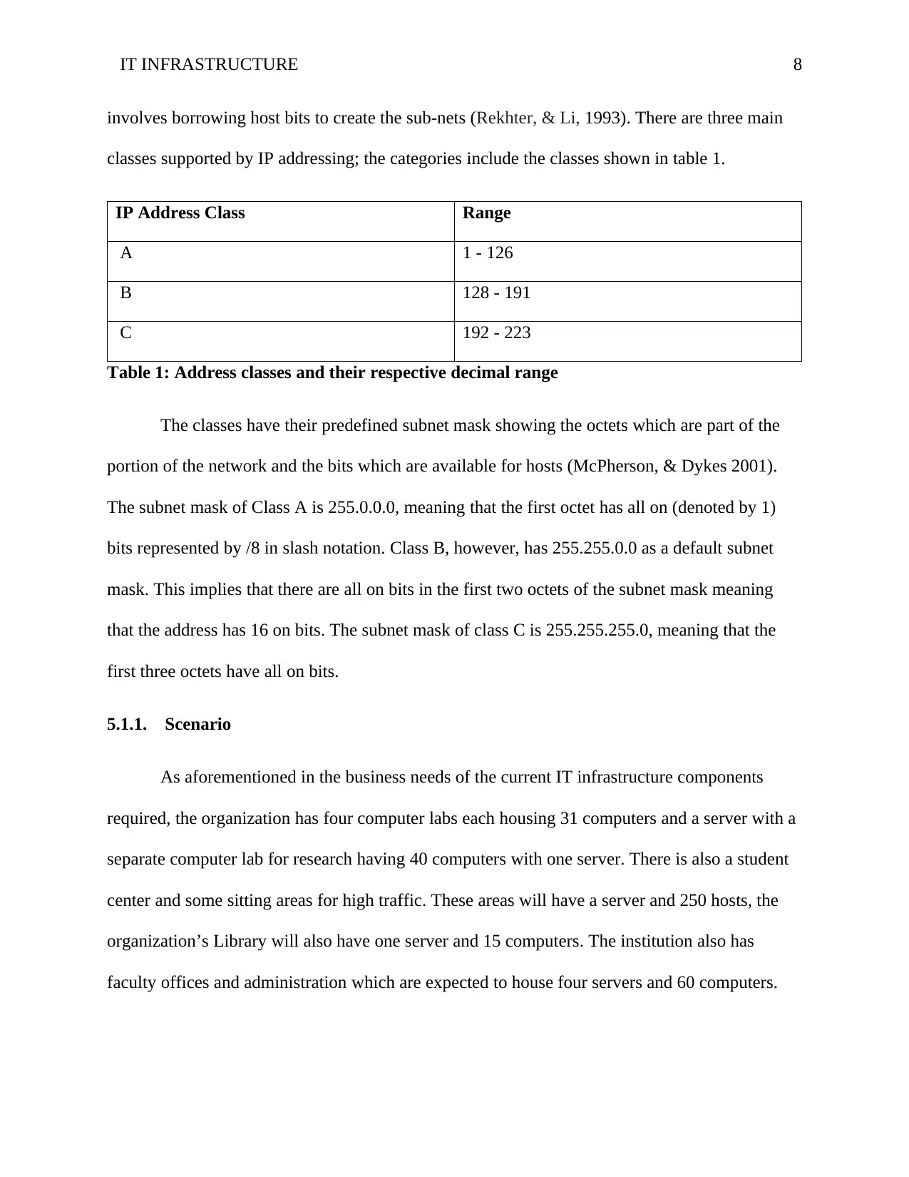
involves borrowing host bits to create the sub-nets (Rekhter, & Li, 1993). There are three main
classes supported by IP addressing; the categories include the classes shown in table 1.
IP Address Class Range
A 1 - 126
B 128 - 191
C 192 - 223
Table 1: Address classes and their respective decimal range
The classes have their predefined subnet mask showing the octets which are part of the
portion of the network and the bits which are available for hosts (McPherson, & Dykes 2001).
The subnet mask of Class A is 255.0.0.0, meaning that the first octet has all on (denoted by 1)
bits represented by /8 in slash notation. Class B, however, has 255.255.0.0 as a default subnet
mask. This implies that there are all on bits in the first two octets of the subnet mask meaning
that the address has 16 on bits. The subnet mask of class C is 255.255.255.0, meaning that the
first three octets have all on bits.
5.1.1. Scenario
As aforementioned in the business needs of the current IT infrastructure components
required, the organization has four computer labs each housing 31 computers and a server with a
separate computer lab for research having 40 computers with one server. There is also a student
center and some sitting areas for high traffic. These areas will have a server and 250 hosts, the
organization’s Library will also have one server and 15 computers. The institution also has
faculty offices and administration which are expected to house four servers and 60 computers.
IT INFRASTRUCTURE 9
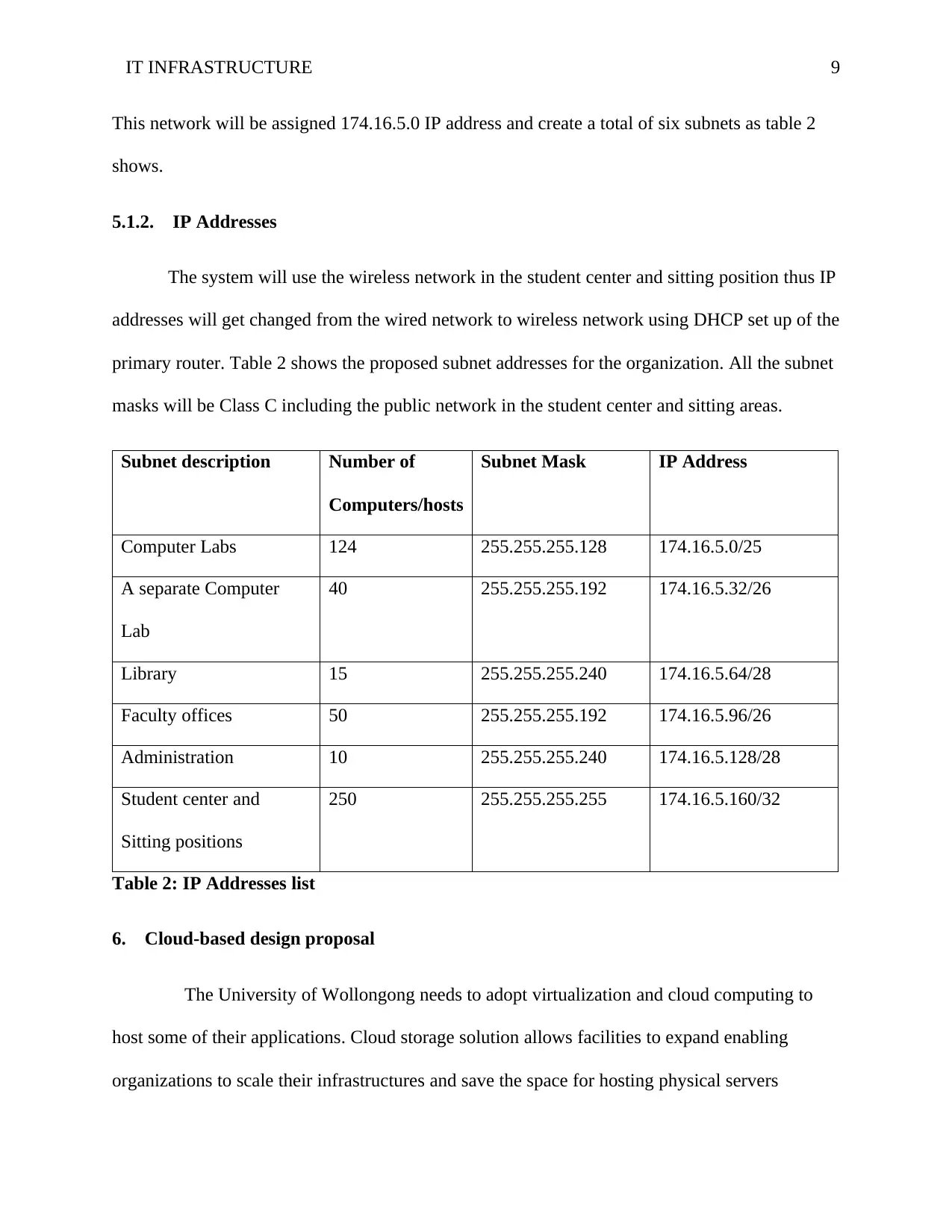
This network will be assigned 174.16.5.0 IP address and create a total of six subnets as table 2
shows.
5.1.2. IP Addresses
The system will use the wireless network in the student center and sitting position thus IP
addresses will get changed from the wired network to wireless network using DHCP set up of the
primary router. Table 2 shows the proposed subnet addresses for the organization. All the subnet
masks will be Class C including the public network in the student center and sitting areas.
Subnet description Number of
Computers/hosts
Subnet Mask IP Address
Computer Labs 124 255.255.255.128 174.16.5.0/25
A separate Computer
Lab
40 255.255.255.192 174.16.5.32/26
Library 15 255.255.255.240 174.16.5.64/28
Faculty offices 50 255.255.255.192 174.16.5.96/26
Administration 10 255.255.255.240 174.16.5.128/28
Student center and
Sitting positions
250 255.255.255.255 174.16.5.160/32
Table 2: IP Addresses list
6. Cloud-based design proposal
The University of Wollongong needs to adopt virtualization and cloud computing to
host some of their applications. Cloud storage solution allows facilities to expand enabling
organizations to scale their infrastructures and save the space for hosting physical servers
⊘ This is a preview!⊘
Do you want full access?
Subscribe today to unlock all pages.
Trusted by 1+ million students worldwide
IT INFRASTRUCTURE 10
(Stergiou, Psannis, Kim, & Gupta, 2018). This report proposes two good cloud data storage
companies that would meet the organization’s needs based on the experience of various users.
Microsoft Azure is one of the reputable cloud host service providers. The range of
integrated cloud services provided by the organization offers a solution to various organizations
ranging from big data and analytics to the internet of things (Rimal, Choi & Lumb, 2009).
Moreover, Microsoft Azure offers one consistent platform for infrastructures, applications as
well as data that can span various data centers including Microsoft public cloud, and other
service provider data centers.
Another widely used cloud host service provider that would be proposed to the
University of Wollongong is Google Cloud. Google Cloud offers enterprise solutions to
organizations. The cloud platform enables organizations to design and build various applications
and websites. It additionally provides data analytics applications for its users. Aside from this, it
offers Google Apps for business which is currently expanding (Zhang, Cheng, & Boutaba,
2010). For the most, the organization also provide the Software as a Service (SaaS),
Infrastructure as a Service (IaaS) and Platform as a Service (PaaS) for its users (Bhardwaj, Jain,
& Jain, 2010). Moreover, Google has recently unveiled one of its patent pledge that will shield
big data developers and cloud software from litigation, therefore, it would be the most preferable
for the organization’s data storage.
7. Virtualization
7.1. The service virtualizations techniques
Paraphrase This Document
Need a fresh take? Get an instant paraphrase of this document with our AI Paraphraser
IT INFRASTRUCTURE 11
Virtualization involves creating virtual devices, servers, infrastructures, and many more
computer resources. It changes the relationship between hardware and software. It is one of the
foundational elements of cloud computing technology that aid in the utilization of the
capabilities of the cloud to the fullest (Menascé 2005). Various techniques of using service
virtualization include the following: Storage virtualization, Network virtualization, desktop
virtualization, server virtualization, data virtualization and application virtualization (Sun,
Chang, Guo, Wang, & Wang, 2010).
Among the virtualization services, SaaS would be better for the organization’s project.
Despite the fact that SaaS limits its users when it comes to accessing, monitoring and managing
applications compared to IaaS and PaaS, it is the most cost effective thus it would be most
preferably used during the project (Bhardwaj et al. 2010).
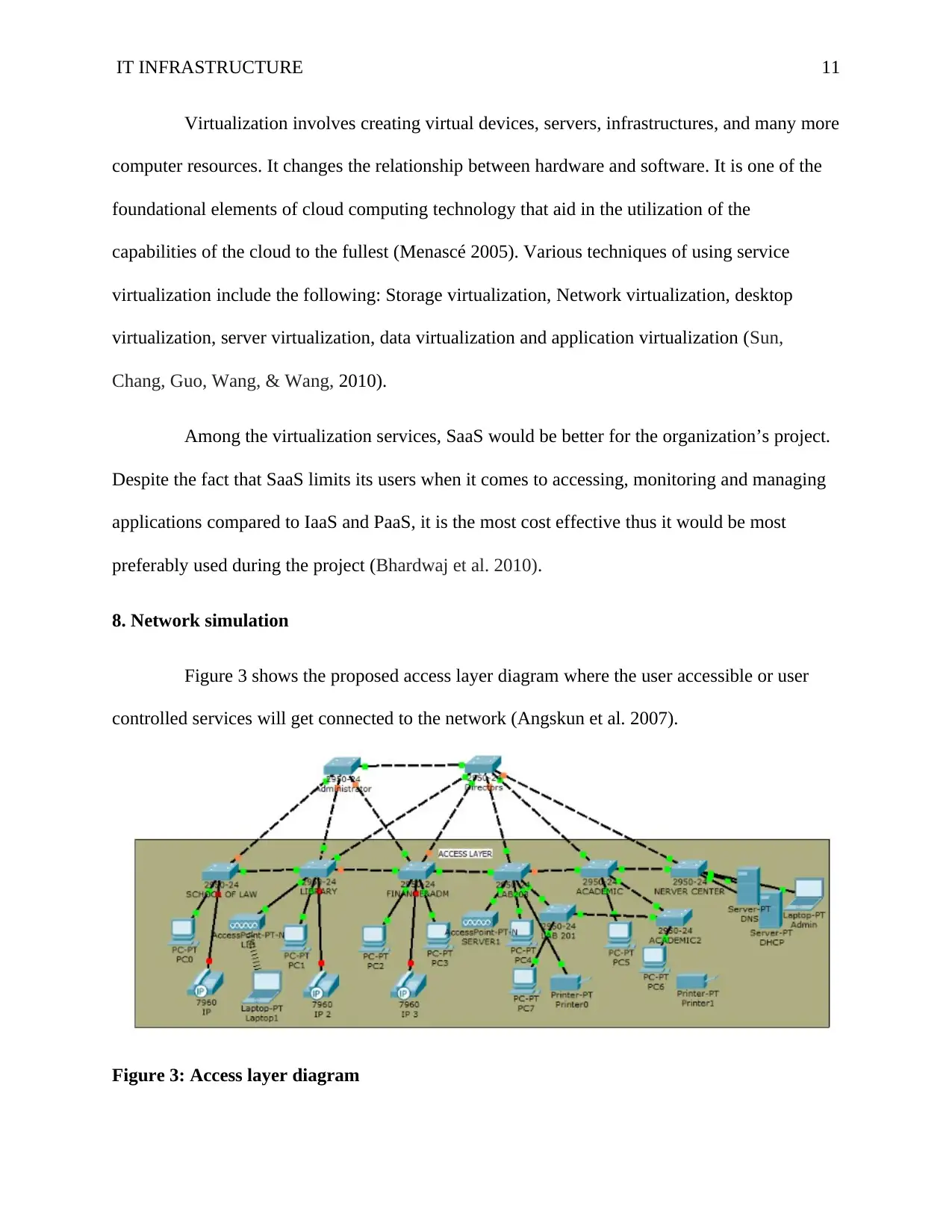
8. Network simulation
Figure 3 shows the proposed access layer diagram where the user accessible or user
controlled services will get connected to the network (Angskun et al. 2007).
Figure 3: Access layer diagram
Virtualization involves creating virtual devices, servers, infrastructures, and many more
computer resources. It changes the relationship between hardware and software. It is one of the
foundational elements of cloud computing technology that aid in the utilization of the
capabilities of the cloud to the fullest (Menascé 2005). Various techniques of using service
virtualization include the following: Storage virtualization, Network virtualization, desktop
virtualization, server virtualization, data virtualization and application virtualization (Sun,
Chang, Guo, Wang, & Wang, 2010).
Among the virtualization services, SaaS would be better for the organization’s project.
Despite the fact that SaaS limits its users when it comes to accessing, monitoring and managing
applications compared to IaaS and PaaS, it is the most cost effective thus it would be most
preferably used during the project (Bhardwaj et al. 2010).
8. Network simulation
Figure 3 shows the proposed access layer diagram where the user accessible or user
controlled services will get connected to the network (Angskun et al. 2007).
Figure 3: Access layer diagram
IT INFRASTRUCTURE 12
8.1. DHCP configuration
The DHCP protocol will get configured to provide quick, automatic and central
management of the IP addresses within the network as well as configuring DNS. In the proposed
network for the University of Wollongong, the routers will act as the DHCP servers. The
configuration will work in a manner that client device will request an IP address from the router
after which the router will assign the IP address to enable the client to communicate through the
network.
8.2. DNS and web server configuration
Keeping the IP addresses of the network in mind is quite hectic. Words can be easily
remembered by human beings compared to strings of numbers, and that is where the domain
name service DNS comes in.
In the proposed DNS and web server configurations, the organization’s clients will
dynamically obtain network configuration and access web server with the organization’s domain,
“uow.edu.au” by typing the domain name i.e. uow.edu.au, into the web browser. The web
browser will first of all find the IP address for the domain name “uow.edu.au” and then contact
the DNS server to query the server’s location where the organization’s web pages are stored. The
DNS server will therefore act as a directory service of the IP addresses of the organization’s
URL.
9. Scaling applications in a virtual cloud computing environment
Cloud computing and virtualization offers new compelling techniques for dealing with
scalable applications (Armbrust et al. 2010). Even though certain applications differ in how they
perform, there are various scaling points where resources get constrained. For instance, there are
⊘ This is a preview!⊘
Do you want full access?
Subscribe today to unlock all pages.
Trusted by 1+ million students worldwide
1 out of 16
Related Documents


Your All-in-One AI-Powered Toolkit for Academic Success.
+13062052269
info@desklib.com
Available 24*7 on WhatsApp / Email
![[object Object]](/_next/static/media/star-bottom.7253800d.svg)
Unlock your academic potential
Copyright © 2020–2026 A2Z Services. All Rights Reserved. Developed and managed by ZUCOL.