NIT1104: Ethernet LAN Design Project for Victoria University - 2018

Verified

Added on  2023/06/11

|7
|593
|351
Project
AI Summary
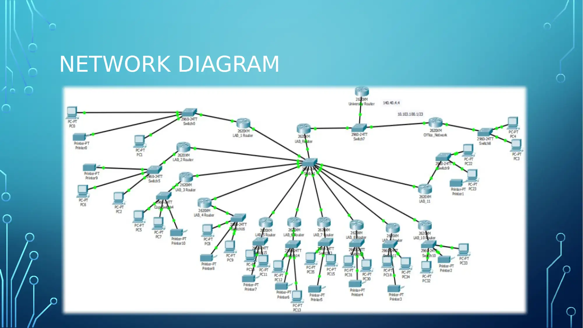
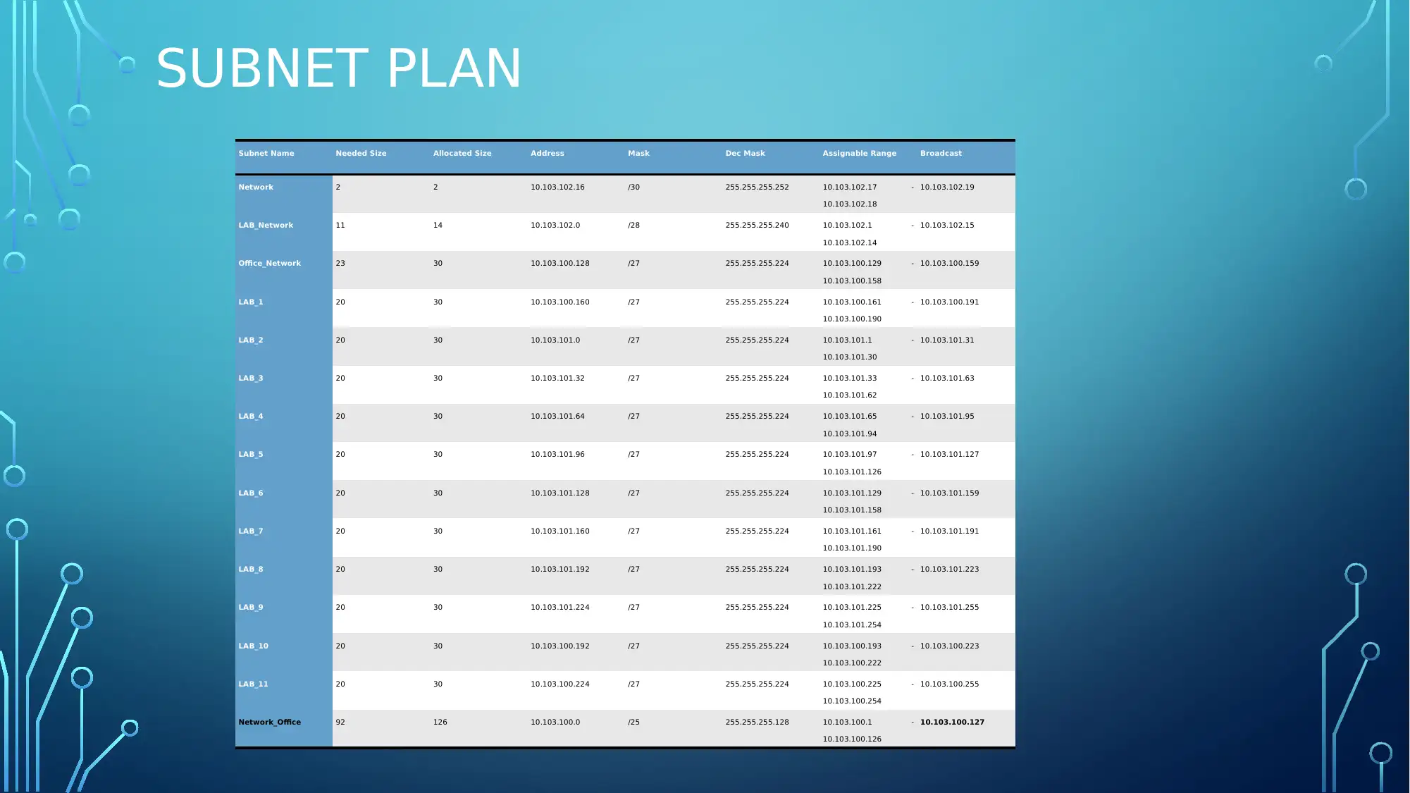
This project outlines the design of an Ethernet LAN for Victoria University, adhering to specific requirements provided in the assignment brief, including the use of a provided floor plan and available Cisco networking devices. The design incorporates separate IP sub-networks for computer labs and offices, connecting to the main campus network and the Internet via a FastEthernet fiber optic link. A detailed subnet plan is included, specifying address masks, assignable ranges, and network sizes. The project also discusses the configuration of a network prototype using Cisco Packet Tracer to identify and mitigate potential barriers during implementation, ensuring a scalable network solution for the university's current and future needs. The document includes network diagrams, subnet planning tables, and a conclusion summarizing the project's key aspects.
Document Page
COMPUTER NETWORKS
NAME OF THE STUDENT
NAME OF THE UNIVERSITY
AUTHOR’S NOTE
tabler-icon-diamond-filled.svg

Paraphrase This Document

Need a fresh take? Get an instant paraphrase of this document with our AI Paraphraser
Document Page
INTRODUCTION
The presentation is prepared for the demonstration of the network plan
created for the Victoria University. For the development of the network
the network is divided into different subnet according to the given floor
plan of the building. The prototype of the network is configured in cisco
packet tracer. A list of the networking device that are required for the
development of the network is created in the documentation part of
the report. It would help the network administrator to identify the
requirement of the network and develop the network according to the
needs of the university.
Document Page
NETWORK DIAGRAM
Document Page
SUBNET PLAN
Subnet Name Needed Size Allocated Size Address Mask Dec Mask Assignable Range Broadcast
Network 2 2 10.103.102.16 /30 255.255.255.252 10.103.102.17 -
10.103.102.18
10.103.102.19
LAB_Network 11 14 10.103.102.0 /28 255.255.255.240 10.103.102.1 -
10.103.102.14
10.103.102.15
Office_Network 23 30 10.103.100.128 /27 255.255.255.224 10.103.100.129 -
10.103.100.158
10.103.100.159
LAB_1 20 30 10.103.100.160 /27 255.255.255.224 10.103.100.161 -
10.103.100.190
10.103.100.191
LAB_2 20 30 10.103.101.0 /27 255.255.255.224 10.103.101.1 -
10.103.101.30
10.103.101.31
LAB_3 20 30 10.103.101.32 /27 255.255.255.224 10.103.101.33 -
10.103.101.62
10.103.101.63
LAB_4 20 30 10.103.101.64 /27 255.255.255.224 10.103.101.65 -
10.103.101.94
10.103.101.95
LAB_5 20 30 10.103.101.96 /27 255.255.255.224 10.103.101.97 -
10.103.101.126
10.103.101.127
LAB_6 20 30 10.103.101.128 /27 255.255.255.224 10.103.101.129 -
10.103.101.158
10.103.101.159
LAB_7 20 30 10.103.101.160 /27 255.255.255.224 10.103.101.161 -
10.103.101.190
10.103.101.191
LAB_8 20 30 10.103.101.192 /27 255.255.255.224 10.103.101.193 -
10.103.101.222
10.103.101.223
LAB_9 20 30 10.103.101.224 /27 255.255.255.224 10.103.101.225 -
10.103.101.254
10.103.101.255
LAB_10 20 30 10.103.100.192 /27 255.255.255.224 10.103.100.193 -
10.103.100.222
10.103.100.223
LAB_11 20 30 10.103.100.224 /27 255.255.255.224 10.103.100.225 -
10.103.100.254
10.103.100.255
Network_Office 92 126 10.103.100.0 /25 255.255.255.128 10.103.100.1 -
10.103.100.126
10.103.100.127
tabler-icon-diamond-filled.svg

Paraphrase This Document

Need a fresh take? Get an instant paraphrase of this document with our AI Paraphraser
Document Page
CONCLUSION
From the presentation it can be concluded that the business rules and the
requirement of the university should be identified for the development of the
network solution. A prototype of the network is configured in packet tracer
for the identification of the barrier that can rise during the commencement of
the project and mitigating it for the mitigation of the risk. The IP address plan
is created for accommodating the present user and the supporting the future
growth of the organization. The local area network is kept simplified by
adding a router for each of the lab and configuration of the interface with the
starting bit of the range of the Ip address of the subnet plan.
Document Page
BIBLIOGRAPHY
Alani, M. M. (2017). Guide to Cisco Routers Configuration: Becoming a Router Geek. Springer.
Biswas, A. K. (2017). Source authentication techniques for network-on-chip router configuration
packets. ACM Journal on Emerging Technologies in Computing Systems (JETC), 13(2), 28.
Kado, Y., Shichijo, D., Deguchi, I., Iwama, N., Kasashima, R., & Wada, K. (2015, November).
Power flow control of three-way isolated DC/DC converter for Y-configuration power router.
In Future Energy Electronics Conference (IFEEC), 2015 IEEE 2nd International (pp. 1-5). IEEE.
Mayoral, A., López, V., Gerstel, O., Palkopoulou, E., de Dios, Ó. G., & Fernández-Palacios, J. P.
(2015). Minimizing resource protection in IP over WDM networks: Multi-layer shared backup
router. Journal of Optical Communications and Networking, 7(3), A440-A446.
Document Page
chevron_up_icon
1 out of 7
circle_padding
hide_on_mobile
zoom_out_icon
[object Object]