University Networking Fundamentals: Assignment 1 Analysis
VerifiedAdded on 2023/02/01
|9
|1261
|78
Homework Assignment
AI Summary
This document presents a comprehensive solution to a networking assignment, addressing several key concepts in electrical engineering. It begins by analyzing a case study involving order processing and communication systems, including a connection diagram illustrating information exchange. The solution then delves into waveform analysis, providing values for amplitude, time period, frequency, and phase for different waveforms. Further, the assignment calculates channel capacity using the Shannon formula, and determines the isotropic free space loss at a given frequency. The document also explores the Nyquist theorem, packet switching, and virtual circuits, comparing their characteristics. Finally, the solution addresses antenna height calculations and concludes with a list of relevant references. This assignment provides a deep dive into networking principles, making it a valuable resource for students.

Networking
Paraphrase This Document
Need a fresh take? Get an instant paraphrase of this document with our AI Paraphraser
NETWORKING 1
Assignment 1
Question 1:
As per the assigned case study it is discussed that guest send a request to the host for taking
their order and host link the order to the clerk for preparing the order. They use the telephone
system for exchanging information with guest and the cock provides the pizza to the guest.
Moreover, the clerk pack the order of guest and transfer to the address of guest by using the
delivery van and receiver get their pizza and the road provides a physical path between guest
and delivery process.
Question 2:
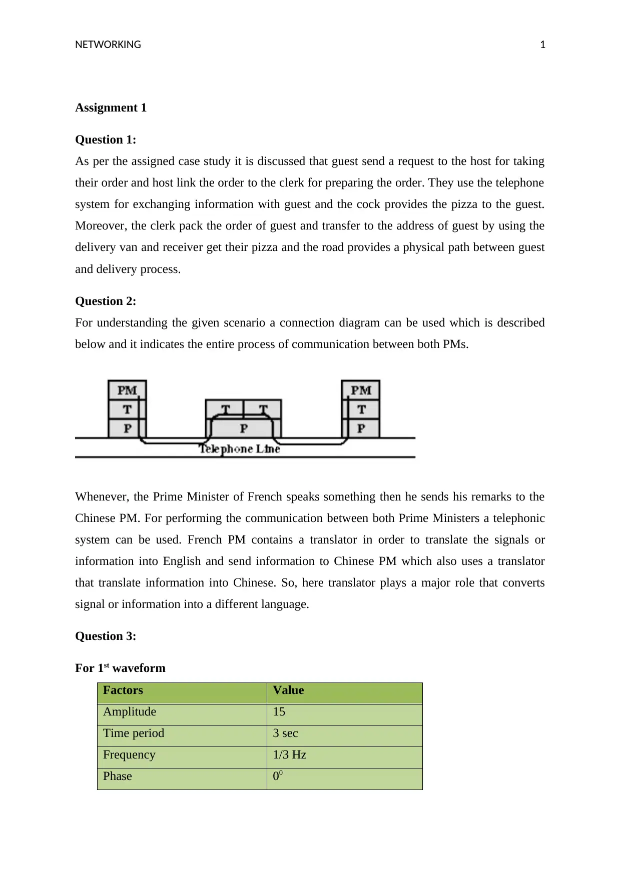
For understanding the given scenario a connection diagram can be used which is described
below and it indicates the entire process of communication between both PMs.
Whenever, the Prime Minister of French speaks something then he sends his remarks to the
Chinese PM. For performing the communication between both Prime Ministers a telephonic
system can be used. French PM contains a translator in order to translate the signals or
information into English and send information to Chinese PM which also uses a translator
that translate information into Chinese. So, here translator plays a major role that converts
signal or information into a different language.
Question 3:
For 1st waveform
Factors Value
Amplitude 15
Time period 3 sec
Frequency 1/3 Hz
Phase 00
NETWORKING 2
For 2nd waveform:
Factors Value
Amplitude 4
Time period 6.5 sec
Frequency 1/6.5 Hz
Phase 00
For 3rd waveform:
Factors Value
Amplitude 7.8
Time period 2.3 sec
Frequency 1/2.3 Hz
Phase 900
Question 4:
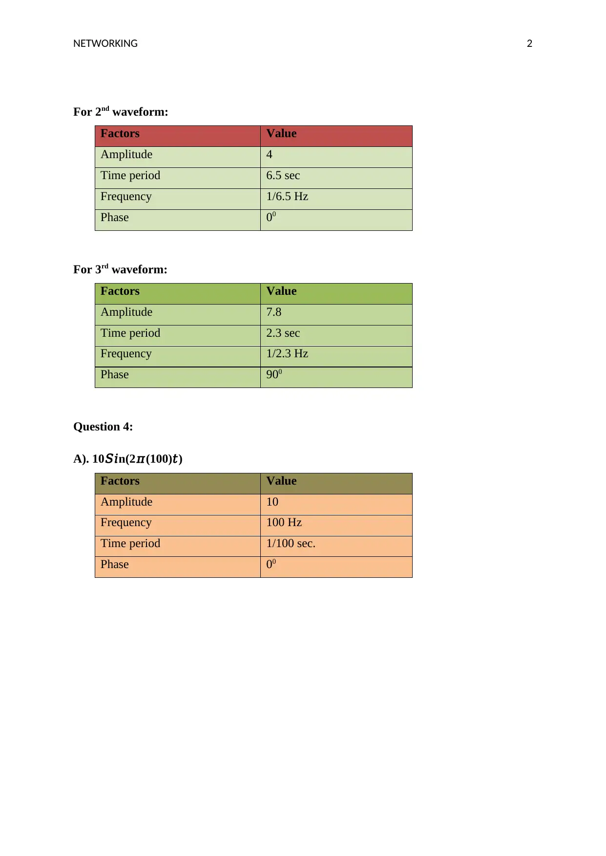
A). 10𝑆𝑖n(2𝜋(100)𝑡)
Factors Value
Amplitude 10
Frequency 100 Hz
Time period 1/100 sec.
Phase 00
For 2nd waveform:
Factors Value
Amplitude 4
Time period 6.5 sec
Frequency 1/6.5 Hz
Phase 00
For 3rd waveform:
Factors Value
Amplitude 7.8
Time period 2.3 sec
Frequency 1/2.3 Hz
Phase 900
Question 4:
A). 10𝑆𝑖n(2𝜋(100)𝑡)
Factors Value
Amplitude 10
Frequency 100 Hz
Time period 1/100 sec.
Phase 00
⊘ This is a preview!⊘
Do you want full access?
Subscribe today to unlock all pages.

Trusted by 1+ million students worldwide
NETWORKING 3
1 13 25 37 49 61 73 85 97
-15
-10
-5
0
5
10
15
Chart Title
time
Amplitude
Axis Title
Axis Title
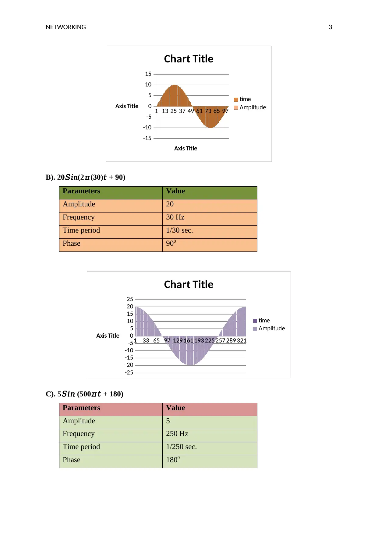
B). 20𝑆𝑖n(2𝜋(30)𝑡 + 90)
Parameters Value
Amplitude 20
Frequency 30 Hz
Time period 1/30 sec.
Phase 900
1 33 65 97 129 161 193 225 257 289 321
-25
-20
-15
-10
-5
0
5
10
15
20
25
Chart Title
time
Amplitude
Axis Title
C). 5𝑆𝑖𝑛 (500𝜋𝑡 + 180)
Parameters Value
Amplitude 5
Frequency 250 Hz
Time period 1/250 sec.
Phase 1800
Paraphrase This Document
Need a fresh take? Get an instant paraphrase of this document with our AI Paraphraser

NETWORKING 4
1 57 113169225281337393
-6
-4
-2
0
2
4
6
time
Amplitude
Axis Title
Axis Title
D). 8𝑆in(400𝜋𝑡 + 270)
Parameters Value
Amplitude 8
Frequency 200 Hz
Time period 1/200 sec.
Phase 2700
1 44 87 130 173 216 259 302 345 388 431 474
-10
-8
-6
-4
-2
0
2
4
6
8
10
time
Amplitude
Axis Title
Axis Title
1 57 113169225281337393
-6
-4
-2
0
2
4
6
time
Amplitude
Axis Title
Axis Title
D). 8𝑆in(400𝜋𝑡 + 270)
Parameters Value
Amplitude 8
Frequency 200 Hz
Time period 1/200 sec.
Phase 2700
1 44 87 130 173 216 259 302 345 388 431 474
-10
-8
-6
-4
-2
0
2
4
6
8
10
time
Amplitude
Axis Title
Axis Title
NETWORKING 5
Question 5:
After reading the provided case study it is examined that the source utilizes a 480*500 pixels
matrix and 30 pictures per second are transferred from the source. Now, sample size= 480 *
500 * 30= 7.2*106.
Moreover, each pixel take one of 32 bits that are log232= 5 which can give the value of
source rate that is source rate R(bps)= 7.2*106*5
R= 36 Mbps
The capacity of the channel can be determined by using the Shannon formula that is C=
B*log2*(1+ SNR).
So, putting the value of B and SNR in the above equation channel capacoty can be calculated
and that is:
C= 4.5*106*log2*(1+ 3162)
C= 52.335*106 bps
Question 6:
In this given case, frequecny is 4 GHz, distance is 35,863 KM and value of isotrpic free space
is determined below:
Free space loss= 20log10 (4*109) +20log10 (35.863*106) - 147.56 dB
Therefore, the value of isotropic free space at 4 GHz is 195.62 dB.
Question 7:
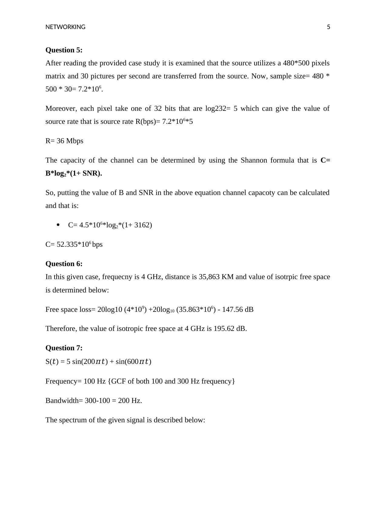
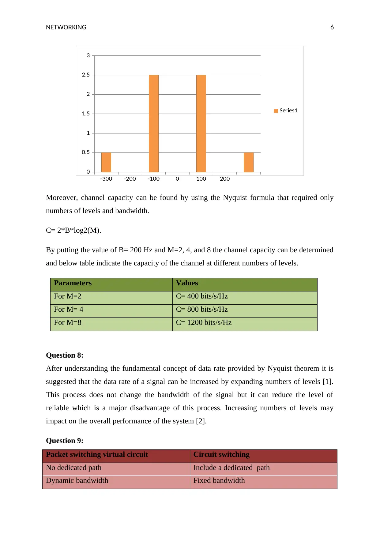
S(𝑡) = 5 sin(200𝜋𝑡) + sin(600𝜋𝑡)
Frequency= 100 Hz {GCF of both 100 and 300 Hz frequency}
Bandwidth= 300-100 = 200 Hz.
The spectrum of the given signal is described below:
⊘ This is a preview!⊘
Do you want full access?
Subscribe today to unlock all pages.

Trusted by 1+ million students worldwide
NETWORKING 6
-300 -200 -100 0 100 200
0
0.5
1
1.5
2
2.5
3
Series1
Moreover, channel capacity can be found by using the Nyquist formula that required only
numbers of levels and bandwidth.
C= 2*B*log2(M).
By putting the value of B= 200 Hz and M=2, 4, and 8 the channel capacity can be determined
and below table indicate the capacity of the channel at different numbers of levels.
Parameters Values
For M=2 C= 400 bits/s/Hz
For M= 4 C= 800 bits/s/Hz
For M=8 C= 1200 bits/s/Hz
Question 8:
After understanding the fundamental concept of data rate provided by Nyquist theorem it is
suggested that the data rate of a signal can be increased by expanding numbers of levels [1].
This process does not change the bandwidth of the signal but it can reduce the level of
reliable which is a major disadvantage of this process. Increasing numbers of levels may
impact on the overall performance of the system [2].
Question 9:
Packet switching virtual circuit Circuit switching
No dedicated path Include a dedicated path
Dynamic bandwidth Fixed bandwidth
Paraphrase This Document
Need a fresh take? Get an instant paraphrase of this document with our AI Paraphraser
NETWORKING 7
Less flexible [3]. More flexible
The route is developed for a complete system The path is developed for the complete
process [4].
Advantages of packet switching virtual circuit
More flexible
Does not waste bandwidth
Dynamic bandwidth
Question 10:
From the provided case study it has found that the height of one antenna is twice of another
antenna that means h1=2h2 and distance is 40 KM. Now, the value of height can be found in
the form below function:
D= 3.57*sqrt (kh1+kh2)
Put K=1.3, D=40 and h1=2h2
Therefore, 40= 3.57*1.1547(sqrt(3h2))
Or, h1= 63.3 meters and h2= 32.6 meters
NETWORKING 8
References
[1]. G., Bosco, A., Carena, V., Curri, P. Poggiolini and, F., Forghieri, “Performance
limits of Nyquist-WDM and CO-OFDM in high-speed PM-QPSK systems,” IEEE
Photonics Technology Letters, vol. 22, no. 15, pp.1129-1131, 2010.
[2]. F. Rusek and J.B., Anderson, “Constrained capacities for faster-than-Nyquist
signalling,” IEEE Transactions on Information Theory, vol. 55, no. 2, pp.764-775,
2009.
[3]. N.E., Jerger, L.S. Peh and, M., Lipasti, “Virtual circuit tree multicasting: A case for
on-chip hardware multicast support,” In 2008 International Symposium on Computer
Architecture, vol. 12, no. 4, pp. 229-240, 2008.
[4]. T., Takuno, M. Koyama and, T., Hikihara, “In-home power distribution systems by
circuit switching and power packet dispatching,” In 2010 First IEEE International
Conference on Smart Grid Communications, vol. 4, no. 5, pp. 427-430, 2010.
⊘ This is a preview!⊘
Do you want full access?
Subscribe today to unlock all pages.

Trusted by 1+ million students worldwide
1 out of 9
Related Documents
Your All-in-One AI-Powered Toolkit for Academic Success.
+13062052269
info@desklib.com
Available 24*7 on WhatsApp / Email
![[object Object]](/_next/static/media/star-bottom.7253800d.svg)
Unlock your academic potential
Copyright © 2020–2025 A2Z Services. All Rights Reserved. Developed and managed by ZUCOL.


