SBM4104 IT Infrastructure: ABC Enterprise Branch Network Design Report
VerifiedAdded on 2023/02/01
|15
|3526
|60
Report
AI Summary
This report details a comprehensive network design for a new branch of ABC Enterprise, an organization seeking efficient communication, data transfer, and resource accessibility. The report proposes a scalable and efficient network for an 8-floor building in Sydney, with each floor containing 30 rooms...
NETWORKING
Paraphrase This Document
Need a fresh take? Get an instant paraphrase of this document with our AI Paraphraser
Table of Contents
Report..............................................................................................................................................2
Introduction......................................................................................................................................2
Geographical Scope.........................................................................................................................3
Assumptions.................................................................................................................................4
Existing Network.........................................................................................................................5
Logical Design.................................................................................................................................5
Requirements...............................................................................................................................6
Network design scenario..............................................................................................................6
Configurations..............................................................................................................................7
Three-layers hierarchal model.....................................................................................................8
1. Core Layer.........................................................................................................................8
2. Distribution Layer.............................................................................................................8
3. Access Layer.....................................................................................................................8
The IP address and subnet mask......................................................................................................8
Virtual Local Area Network (VLAN).............................................................................................9
Cloud Providers.............................................................................................................................10
1. Google cloud.......................................................................................................................10
2. Microsoft Azure..................................................................................................................11
Service Virtualization technique....................................................................................................11
Dynamic scaling using Cloud computing......................................................................................12
Summary........................................................................................................................................14
Referencess....................................................................................................................................15
1
Introduction
In every organization, there is a desire for efficient and effective communication, data transfer
and better resources accessibility. All these desires are made to be true when the network within
the organization is well designed according to the established rules. ABC an enterprise wants to
open a another branch in a newly acquired building at Sydney. This report proposes a network
design for the branch that is located in an 8 floor building. Each floor containing 30 rooms each
with five workstations. Design of the network should be scalable and efficient in order to fulfil
the requirements of the organization. The logical diagrams, IP addressing plans and geographical
scopes of the network are well explained in this report.
Geographical Scope
The proposed network is designed to serve the new branch of ABC enterprise organization at
Sydeney. The building has 8 floors with 30 rooms every on every floor where there will be 5
network points for connecting staff PCs. These floors have different requirements. Every floor
will have the same number of computers and access points for wireless connection apart from the
2nd floor where the server room with a file, print, DHCP and DNS servers together with a
Firewall system providing the edge for the internet and branch offices.
The network designed is expected to achieve some objectives (Montreuil, B. and Poulin *,
2015):
To provide secure services within the organization and this is done so by isolating it
physically and functionally from being accessed by people who are not employees hence
minimizing cases of unauthorized access.
To provide a room for future expansion when there is need to scale up the network either
by adding more devices, cables, network peripherals.
To process information effectively that is the user is able to store, retrieve, or process
data regarding the ABC organization.
2
You're viewing a preview
Unlock full access by subscribing today!
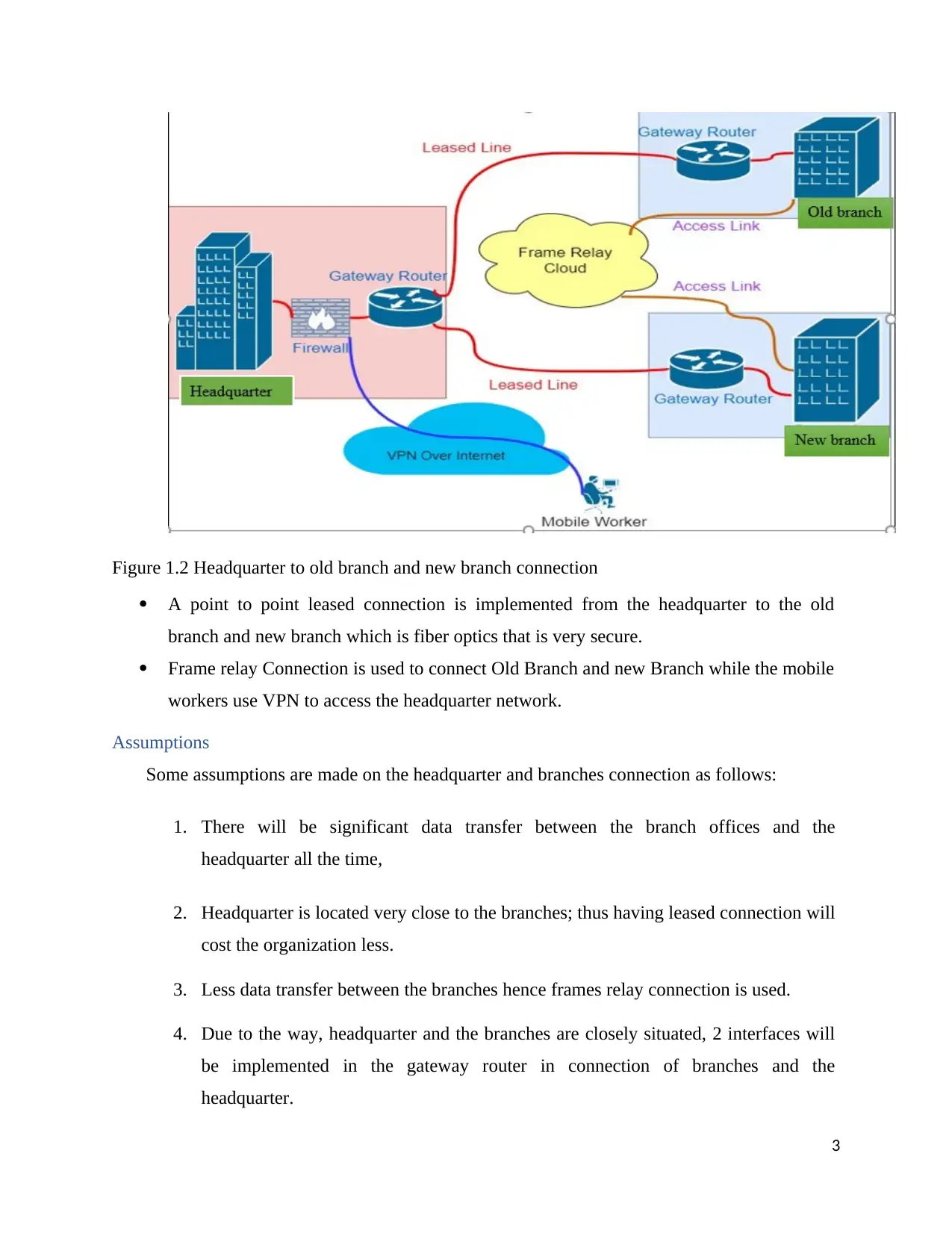
Figure 1.2 Headquarter to old branch and new branch connection
A point to point leased connection is implemented from the headquarter to the old
branch and new branch which is fiber optics that is very secure.
Frame relay Connection is used to connect Old Branch and new Branch while the mobile
workers use VPN to access the headquarter network.
Assumptions
Some assumptions are made on the headquarter and branches connection as follows:
1. There will be significant data transfer between the branch offices and the
headquarter all the time,
2. Headquarter is located very close to the branches; thus having leased connection will
cost the organization less.
3. Less data transfer between the branches hence frames relay connection is used.
4. Due to the way, headquarter and the branches are closely situated, 2 interfaces will
be implemented in the gateway router in connection of branches and the
headquarter.
3
Paraphrase This Document
Need a fresh take? Get an instant paraphrase of this document with our AI Paraphraser
Existing Network
By the assumptions made, there is an existing network that used in the headquarter and the old
branch using leased line. The headquarter uses a single interface on its gateway router to connect
to the old branch gateway interface. The proposed network design of the new branch will
connect to the existing network with the help of point to point leased lines to the headquarter
network and to the old branch using frame relay. A new interface in the headquarter network
gateway router is configured to connect to the new branch network. Also, in the old branch
network gateway router another interface is configured to connect with the new branch network.
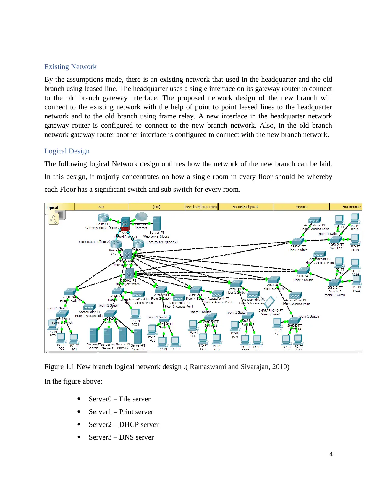
Logical Design
The following logical Network design outlines how the network of the new branch can be laid.
In this design, it majorly concentrates on how a single room in every floor should be whereby
each Floor has a significant switch and sub switch for every room.
Figure 1.1 New branch logical network design .( Ramaswami and Sivarajan, 2010)
In the figure above:
Server0 – File server
Server1 – Print server
Server2 – DHCP server
Server3 – DNS server
4
Multilayer switch1 – core switch 2
Multilayer switch0 – core switch 1
Requirements
1. Servers (DHCP server, file server, DNS server, print server, web server,)
2. Firewall
3. Routers
4. Access points
5. 2 multilayer switches
6. Switches
7. Connecting cables
8. Internet service provider
9. Computers
Network design scenario
• The new branch consists of 8 floors which have different requirements.
• Everywhere in the building is supposed to have wireless internet connection
through the help of the installed access points in different rooms (Carolan,
Oracle America, 2010).
• The server room will be housed on the 2nd floor and IT Offices. This floor
has a gateway router that will assist in communication with the head offices
remotely.
• A firewall is still installed to ensure security in the internal and to provide an
edge for the offices in the branch and internet.
• The first floor is for all customers and customer care services.
• The chief technical officers, chief executive officer's offices and significant
seniors will be located on the Third floor.
• The fourth floor will house all finance offices, fifth floor - Human resource
offices, Sixth floor - Marketing, seventh floor - workplace, and Eighth floor
– Research and extension offices.
5
You're viewing a preview
Unlock full access by subscribing today!
• Each room has a switch which helps in network extension and expansion.
Configurations
Structured cabling is always an efficient approach while designing a network. There are
subsystems in the network which are: the internet service provider network ends at the entrance
of the facility and then connect to the devices of the customer, server or the equipment room
where network parts that serve the users in the building ,interconnection horizontal cabling for
connecting network components in the same floor, backbone cabling (connecting different floors
in the building), telecommunication close where backbone and horizontal cabling are
interconnected and End users equipment area (Enns, Bjorklund, Schoenwaelder and Bierman,
2011).
So, in this design, structured cabling is implemented. In every room, there are several ends users’
devices (PCs) that uses RJ45 ethernet cables to connect to a wall socket for internet access, and
also access points (AP) are installed for wireless connection.
The core switches in the second floor have backbone links that connect to the main switch in
every floor where 2 core switches are used to provide connection redundancy whenever a failure
occurs and to eliminate single point of failure.
The web server should be situated in a DMZ (demilitarized zone) because of internal and
external access to prevent malicious people from getting into the branch network. It is assigned
a static IP address to avoid downtime when IP addresses are being renewed. Web server is
connected to the firewall which is used for traffic filtering that is getting into the internal
network using ACL (Access Control List) that is already configured inside the firewall.
Routing traffic within the building (that is among the VLANs) and outside the branch is done by
core router whereby two core routers are used for the same reason of having two core switches,
providing redundancy and single point of failure avoidance (Yoon, Yang and Lee, 2019). Every
core router is connected to each core switch cables of very high speed.
A gateway router is connected to the firewall. It is implemented to route or forwards traffic to
the other branch, and the headquarter using leased lines.
6
Paraphrase This Document
Need a fresh take? Get an instant paraphrase of this document with our AI Paraphraser
In the second floor, there are different servers which are connected to a single switch that is
connected to both core switches. DNS server is used in translating a domain name to specific IP
addresses, and the DHCP server is used in assigning IP addresses dynamically in the network
(Woundy and Kinnear, 2016).
Internet Service Provider is part of the entrance facility subsystem where it is demonstrated by
the connection between the firewall and the internet cloud. ISP provides internet connection to
the network in ABC organization.
Three-layers hierarchal model
Every network infrastructure has 3 layers:
1. Core Layer
It ensures that there is a high-speed connection in the distribution layer, access layer, data
center (server room) and edge distribution. In this layer, the implementation of
redundancy is highly considered to ensure there are availability and reliability (Fu, Bi,
Gao, Chen, Z., Wu, and Hao, 2014).
2. Distribution Layer
It is well configured to ensure access between the core layer and the workstations or work
groups. It ensures there is control on services access and also switches and links
redundancy are implemented (Ausiello, Apicella and Davidson, 2012).
3. Access Layer
It is situated within the building. Different end users and workgroups fall under this layer
which provides a link to the distribution layer. All the devices that allow users who are
authorized, access the network (Pfaff, Pettit, Amidon, Casado, Koponen and Shenker,
2009).
7
\
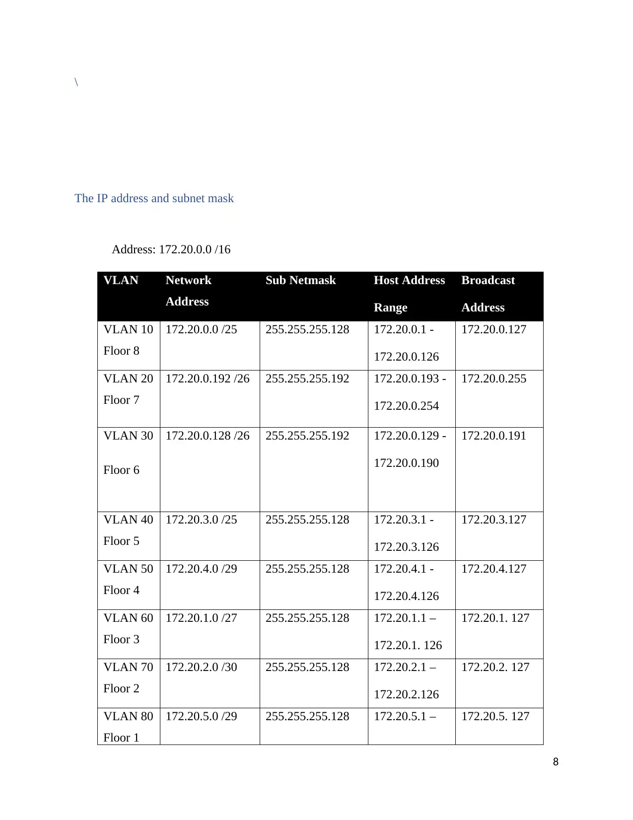
The IP address and subnet mask
Address: 172.20.0.0 /16
VLAN Network
Address
Sub Netmask Host Address
Range
Broadcast
Address
VLAN 10
Floor 8
172.20.0.0 /25 255.255.255.128 172.20.0.1 -
172.20.0.126
172.20.0.127
VLAN 20
Floor 7
172.20.0.192 /26 255.255.255.192 172.20.0.193 -
172.20.0.254
172.20.0.255
VLAN 30
Floor 6
172.20.0.128 /26 255.255.255.192 172.20.0.129 -
172.20.0.190
172.20.0.191
VLAN 40
Floor 5
172.20.3.0 /25 255.255.255.128 172.20.3.1 -
172.20.3.126
172.20.3.127
VLAN 50
Floor 4
172.20.4.0 /29 255.255.255.128 172.20.4.1 -
172.20.4.126
172.20.4.127
VLAN 60
Floor 3
172.20.1.0 /27 255.255.255.128 172.20.1.1 –
172.20.1. 126
172.20.1. 127
VLAN 70
Floor 2
172.20.2.0 /30 255.255.255.128 172.20.2.1 –
172.20.2.126
172.20.2. 127
VLAN 80
Floor 1
172.20.5.0 /29 255.255.255.128 172.20.5.1 – 172.20.5. 127
8
You're viewing a preview
Unlock full access by subscribing today!
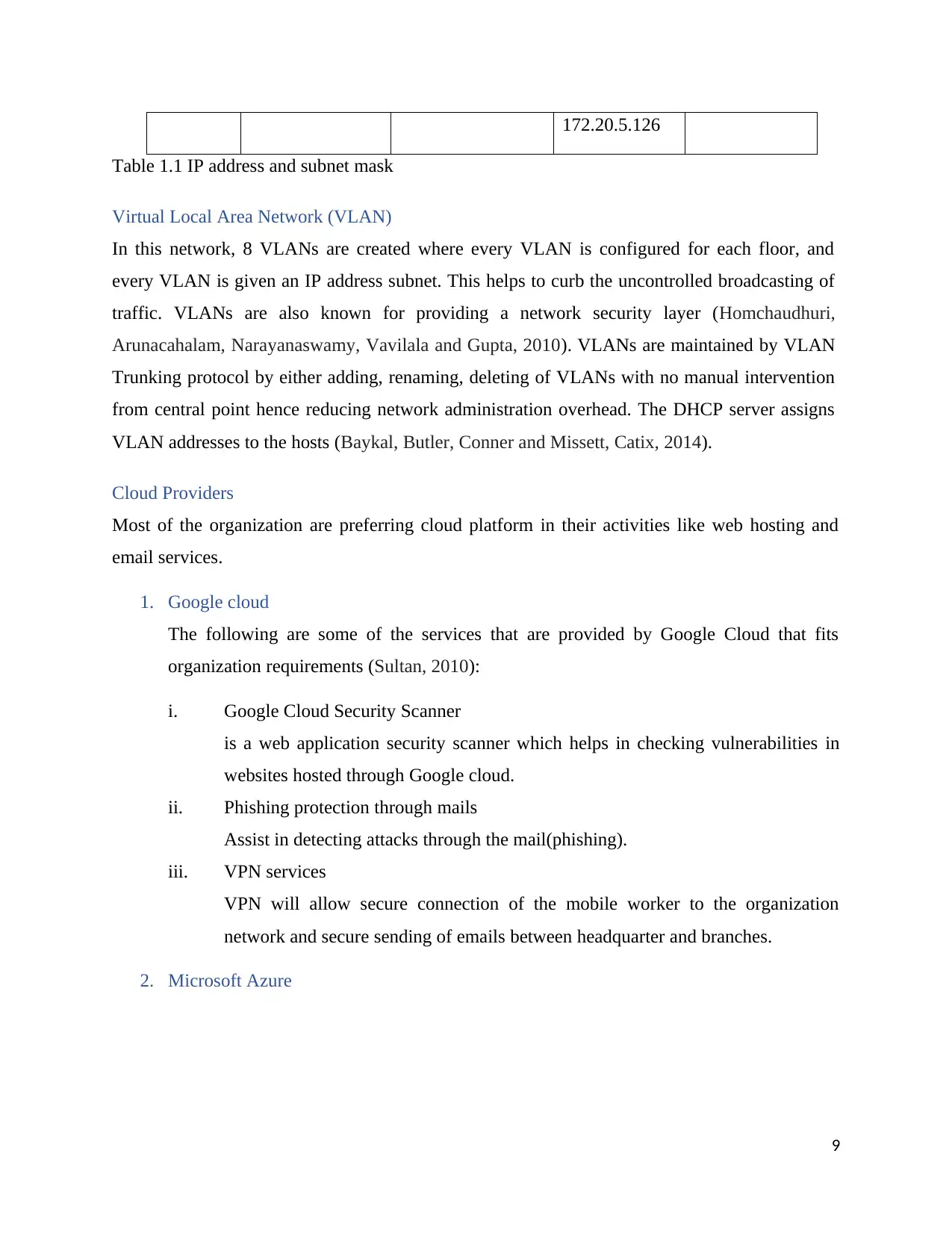
172.20.5.126
Table 1.1 IP address and subnet mask
Virtual Local Area Network (VLAN)
In this network, 8 VLANs are created where every VLAN is configured for each floor, and
every VLAN is given an IP address subnet. This helps to curb the uncontrolled broadcasting of
traffic. VLANs are also known for providing a network security layer (Homchaudhuri,
Arunacahalam, Narayanaswamy, Vavilala and Gupta, 2010). VLANs are maintained by VLAN
Trunking protocol by either adding, renaming, deleting of VLANs with no manual intervention
from central point hence reducing network administration overhead. The DHCP server assigns
VLAN addresses to the hosts (Baykal, Butler, Conner and Missett, Catix, 2014).
Cloud Providers
Most of the organization are preferring cloud platform in their activities like web hosting and
email services.
1. Google cloud
The following are some of the services that are provided by Google Cloud that fits
organization requirements (Sultan, 2010):
i. Google Cloud Security Scanner
is a web application security scanner which helps in checking vulnerabilities in
websites hosted through Google cloud.
ii. Phishing protection through mails
Assist in detecting attacks through the mail(phishing).
iii. VPN services
VPN will allow secure connection of the mobile worker to the organization
network and secure sending of emails between headquarter and branches.
2. Microsoft Azure
9
Paraphrase This Document
Need a fresh take? Get an instant paraphrase of this document with our AI Paraphraser
i. Azure provides email services through a cloud-based email service called
SendGrid which ensures there is reliable delivery of emails, real-time analytics
and scalability (Wilder, 2012).
ii. It also provides a platform as a service environment where the organization is able
to monitor and manage their website.
iii. It also offers storage services which may also act as backup storage for the
organization.
Service Virtualization technique
Enable simulation of services in the cloud which are very expensive. Complex
applications may rely highly on many services which organization cannot host or own.
So, it helps the organization to easily and quickly create an environment for production
hence ensuring proper functioning of the applications for the end devices or users
(Kertesz, Kecskemeti, and Brandic, 2009,).
Service Virtualization simulates components behaviors hard to access during testing.
These components can be APIs, networks, devices, storage, and many more. There are
reasons why such components or resources are unavailable or hard to access:
They may be under development,
On maintenance,
Hard to set up
Very expensive
Requires expert supervision
Through service virtualization, developers are able to test their software at any stage of
software development cycle where in this case, the organization is able to utilize
virtualization in different activities e.g. the organization can deploy their website and
keep on updating whenever there is a change quickly at any point while testing how it
looks, the organization may also be in need of extra storage services, and they can
purchase a storage at the moment (Kertesz, Kecskemeti and Brandic, 2011,).
10
Dynamic scaling using Cloud computing
Scalability in cloud computing is essential in the ABC organization because it measures
application ability and capacity to expand.
Generally, applications can be scaled up by adding more resources (storage, processors, network
bandwidth) whenever there is need. So, the applications which are scalable can perform their
operations typically as they continue to grow while more resources are still added to cope with
the customers' demands at any time (Buyya, Ranjan. and Calheiros 2010).
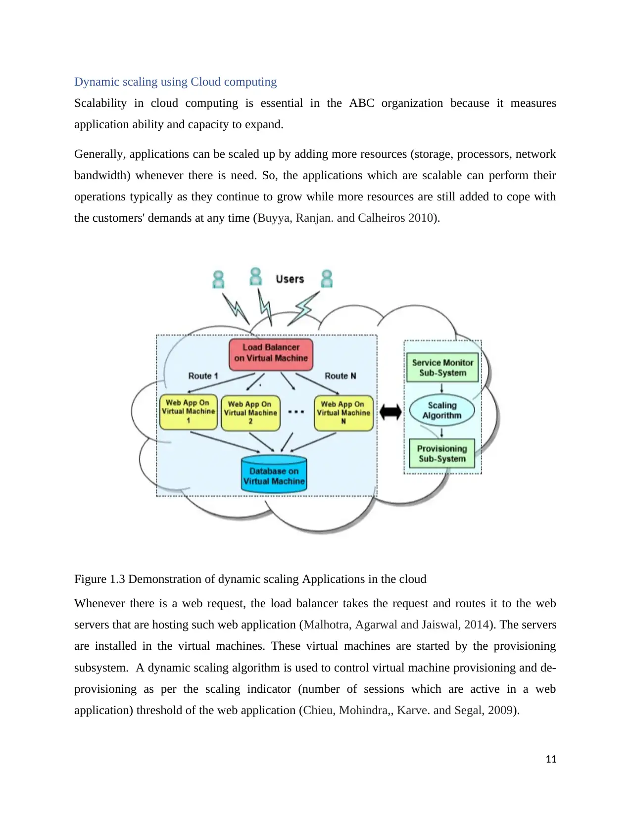
Figure 1.3 Demonstration of dynamic scaling Applications in the cloud
Whenever there is a web request, the load balancer takes the request and routes it to the web
servers that are hosting such web application (Malhotra, Agarwal and Jaiswal, 2014). The servers
are installed in the virtual machines. These virtual machines are started by the provisioning
subsystem. A dynamic scaling algorithm is used to control virtual machine provisioning and de-
provisioning as per the scaling indicator (number of sessions which are active in a web
application) threshold of the web application (Chieu, Mohindra,, Karve. and Segal, 2009).
11
You're viewing a preview
Unlock full access by subscribing today!
Service Monitor sub-system implements scaling algorithm, which is in charge of controlling and
triggering the scaling of provisioning sub-system based in scaling indicator statistics. (Vaquero,
Rodero-Merino, and Buyya., 2011). The scaling pointer that we select here is the quantity of
dynamic sessions or login sessions in each web application.
Summary
The proposed network ensures they are implemented: security in the Internet where firewall is
installed, availability-this is ensured by the level of redundancy within the network, for instance,
there are two core switches and core routers that are installed, also wireless connection is ensured
in the whole building through installation of access points in every floor thus any employee who
wants to use his smartphone or laptop and there isn't wall socket for Ethernet he or she can use
wireless connection.
In the network architecture, there is 3 hierarchical models' network for every efficient network:
core layer, distribution layer and access layer. They have to rely on each other. VLANs provide a
mother layer of network security where in our case every floor is given its VLAN.
12
Paraphrase This Document
Need a fresh take? Get an instant paraphrase of this document with our AI Paraphraser
Referencess
Ausiello, P., Apicella, A. and Davidson, C.L., 2012. Effect of adhesive layer properties on stress
distribution in composite restorations—a 3D finite element analysis. Dental Materials, 18(4),
pp.295-303.
Baykal, B., Butler, D.M., Conner, M.W. and Missett, S.N., Catix, Inc., 2014. Isolation VLAN for
layer two access networks. U.S. Patent 8,875,233.
Buyya, R., Ranjan, R. and Calheiros, R.N., 2010, May. Intercloud: Utility-oriented federation of
cloud computing environments for scaling of application services. In International Conference
on Algorithms and Architectures for Parallel Processing (pp. 13-31). Springer, Berlin,
Heidelberg.
Carolan, J.T., Oracle America Inc, 2010. Logical service domains for enabling network mobility.
U.S. Patent 7,751,409.
Chieu, T.C., Mohindra, A., Karve, A.A. and Segal, A., 2009, October. Dynamic scaling of web
applications in a virtualized cloud computing environment. In 2009 IEEE International
Conference on e-Business Engineering (pp. 281-286). IEEE.
Enns, R., Bjorklund, M., Schoenwaelder, J. and Bierman, A., 2011. Network configuration
protocol (NETCONF) (No. RFC 6241).
Fu, Y., Bi, J., Gao, K., Chen, Z., Wu, J. and Hao, B., 2014, October. Orion: A hybrid hierarchical
control plane of software-defined networking for large-scale networks. In 2014 IEEE 22nd
International Conference on Network Protocols (pp. 569-576). IEEE.
Homchaudhuri, S., Arunacahalam, S., Narayanaswamy, S., Vavilala, K.K. and Gupta, A., Cisco
Technology Inc, 2010. Platform independent implementation of private VLANS. U.S. Patent
7,808,992.
Kertesz, A., Kecskemeti, G. and Brandic, I., 2009, June. An SLA-based resource virtualization
approach for on-demand service provision. In Proceedings of the 3rd international workshop on
Virtualization technologies in distributed computing (pp. 27-34). ACM.
Kertesz, A., Kecskemeti, G. and Brandic, I., 2011, February. Autonomic sla-aware service
virtualization for distributed systems. In 2011 19th international Euromicro conference on
parallel, distributed and network-based processing (pp. 503-510). IEEE.
Malhotra, L.A.K.S.H.A.Y., Agarwal, D. and Jaiswal, A., 2014. Virtualization in cloud
computing. J Inform Tech Softw Eng, 4(2), p.136.
Montreuil, B. and Poulin *, M. (2015). Demand and supply network design scope for
personalized manufacturing. Production Planning & Control, 16(5), pp.454-469.
Pfaff, B., Pettit, J., Amidon, K., Casado, M., Koponen, T. and Shenker, S., 2009, October.
Extending networking into the virtualization layer. In Hotnets.
13
Ramaswami, R. and Sivarajan, K.N., 2010. Design of logical topologies for wavelength-routed
optical networks. IEEE Journal on Selected areas in communications, 14(5), pp.840-851.
Sultan, N., 2010. Cloud computing for education: A new dawn?. International Journal of
Information Management, 30(2), pp.109-116.
Vaquero, L.M., Rodero-Merino, L. and Buyya, R., 2011. Dynamically scaling applications in the
cloud. ACM SIGCOMM Computer Communication Review, 41(1), pp.45-52.
Wilder, B., 2012. Cloud architecture patterns: using microsoft azure. " O'Reilly Media, Inc.".
Woundy, R. and Kinnear, K., 2016. Dynamic host configuration protocol (DHCP)
leasequery (No. RFC 4388).
Yoon, H.S., Yang, S.H. and Lee, J.H., Electronics and Telecommunications Research Institute,
2009. System and method for VLAN configuration of E-PON, and recording medium with stored
program thereof. U.S. Patent 7,492,768.
14
You're viewing a preview
Unlock full access by subscribing today!
1 out of 15
Related Documents
Your All-in-One AI-Powered Toolkit for Academic Success.
+13062052269
info@desklib.com
Available 24*7 on WhatsApp / Email
![[object Object]](/_next/static/media/star-bottom.7253800d.svg)
Unlock your academic potential
© 2024 | Zucol Services PVT LTD | All rights reserved.


