Wireless Network and Communication
VerifiedAdded on 2023/02/01
|10
|2035
|34
AI Summary
This document discusses the concept of wireless network and communication. It covers topics such as the physical path of delivery in wireless networks, the role of translators in international communication, signal parameters, free space loss, channel capacity, data rate in communication systems, and the differences between circuit switching and packet switching. It also provides examples and calculations related to these topics. Find comprehensive study material, solved assignments, and essays on wireless network and communication at Desklib.
Contribute Materials
Your contribution can guide someone’s learning journey. Share your
documents today.

NETWORKING
0
Wireless network and
communication
0
Wireless network and
communication
Secure Best Marks with AI Grader
Need help grading? Try our AI Grader for instant feedback on your assignments.
NETWORKING
1
Question 1
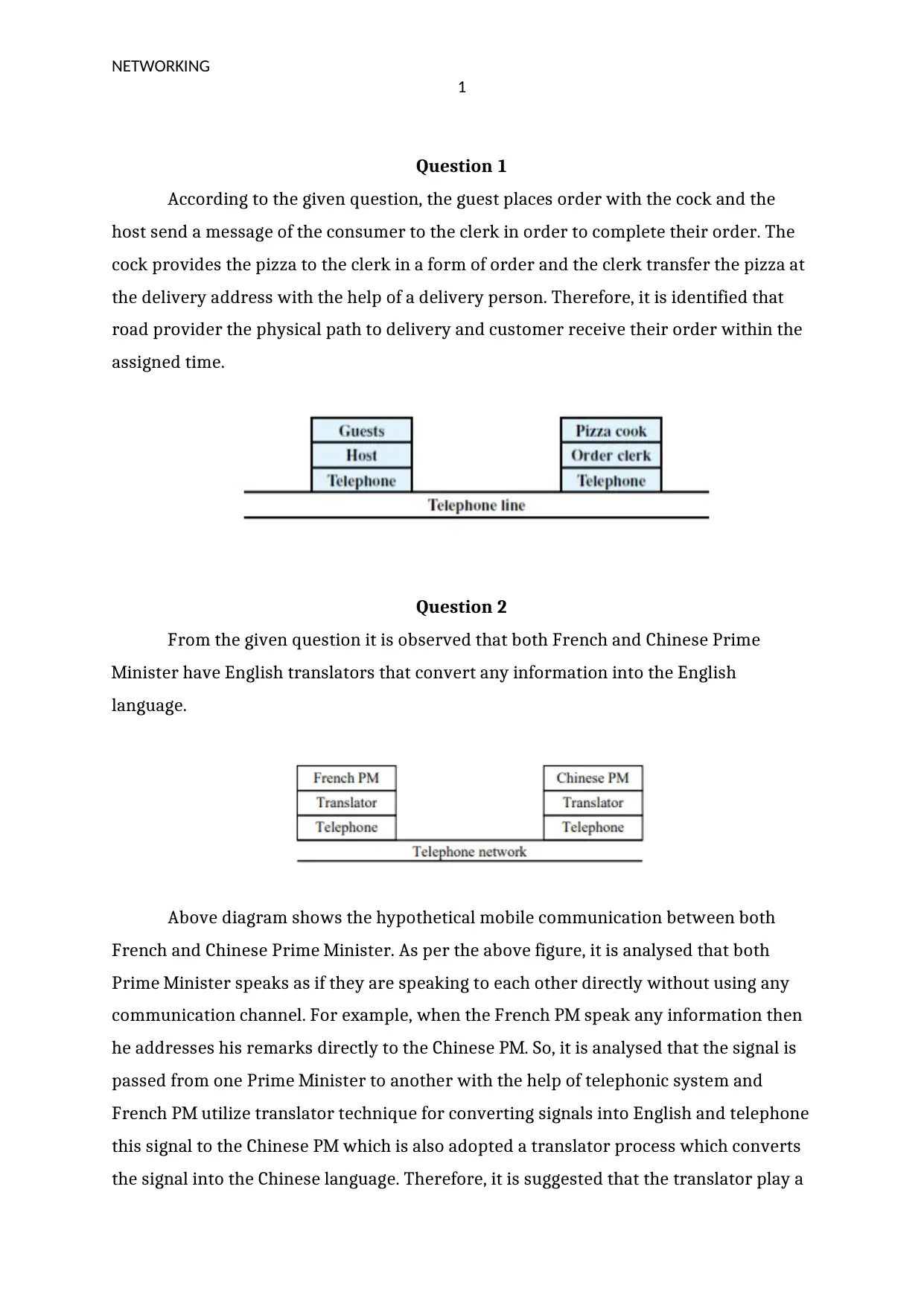
According to the given question, the guest places order with the cock and the
host send a message of the consumer to the clerk in order to complete their order. The
cock provides the pizza to the clerk in a form of order and the clerk transfer the pizza at
the delivery address with the help of a delivery person. Therefore, it is identified that
road provider the physical path to delivery and customer receive their order within the
assigned time.
Question 2
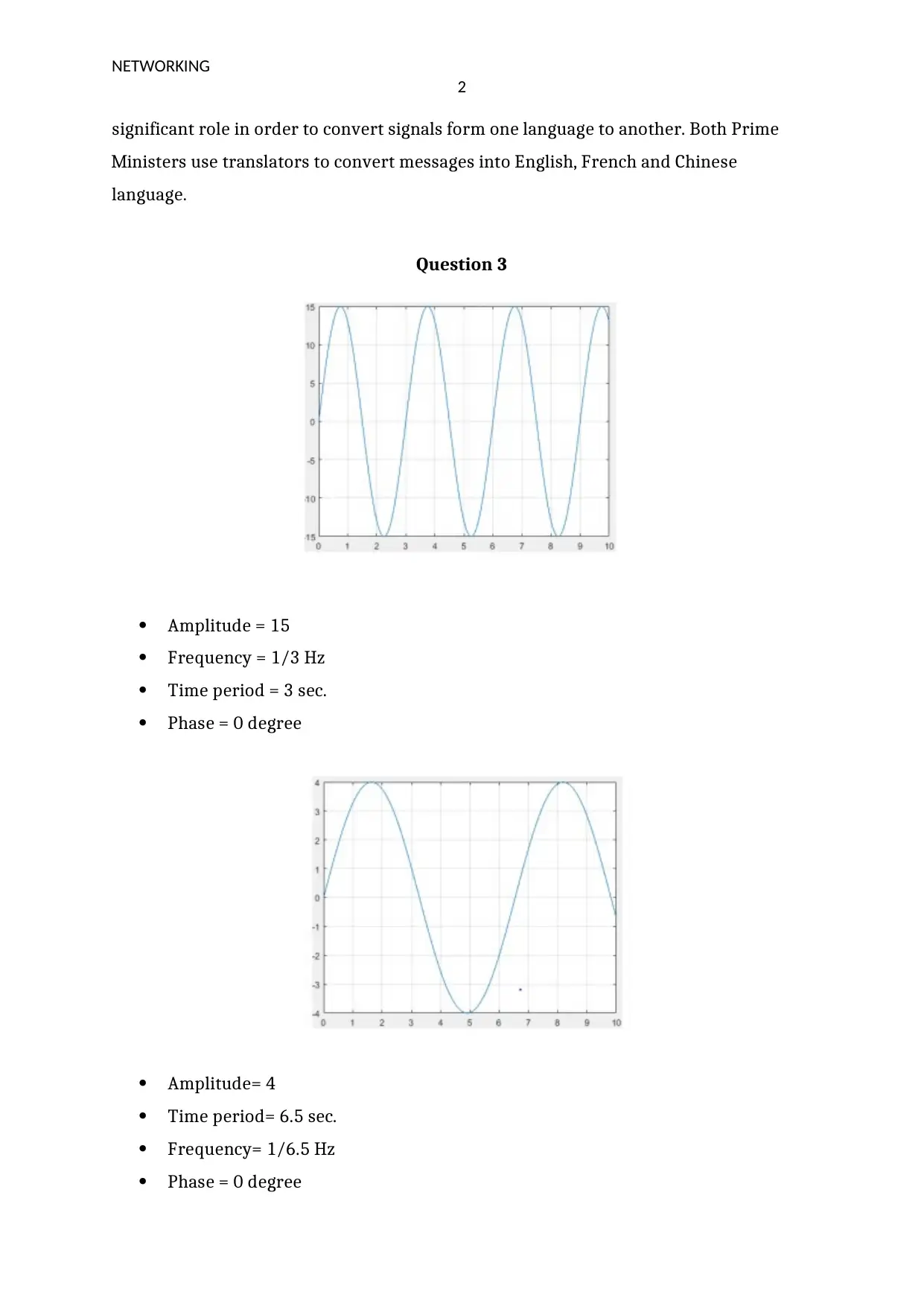
From the given question it is observed that both French and Chinese Prime
Minister have English translators that convert any information into the English
language.
Above diagram shows the hypothetical mobile communication between both
French and Chinese Prime Minister. As per the above figure, it is analysed that both
Prime Minister speaks as if they are speaking to each other directly without using any
communication channel. For example, when the French PM speak any information then
he addresses his remarks directly to the Chinese PM. So, it is analysed that the signal is
passed from one Prime Minister to another with the help of telephonic system and
French PM utilize translator technique for converting signals into English and telephone
this signal to the Chinese PM which is also adopted a translator process which converts
the signal into the Chinese language. Therefore, it is suggested that the translator play a
NETWORKING
2
significant role in order to convert signals form one language to another. Both Prime
Ministers use translators to convert messages into English, French and Chinese
language.
Question 3
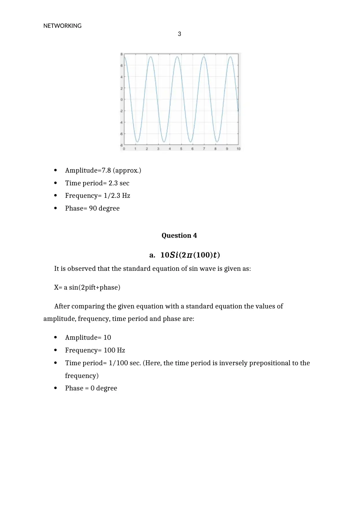
Amplitude = 15
Frequency = 1/3 Hz
Time period = 3 sec.
Phase = 0 degree
Amplitude= 4
Time period= 6.5 sec.
Frequency= 1/6.5 Hz
Phase = 0 degree
NETWORKING
3
Amplitude=7.8 (approx.)
Time period= 2.3 sec
Frequency= 1/2.3 Hz
Phase= 90 degree
Question 4
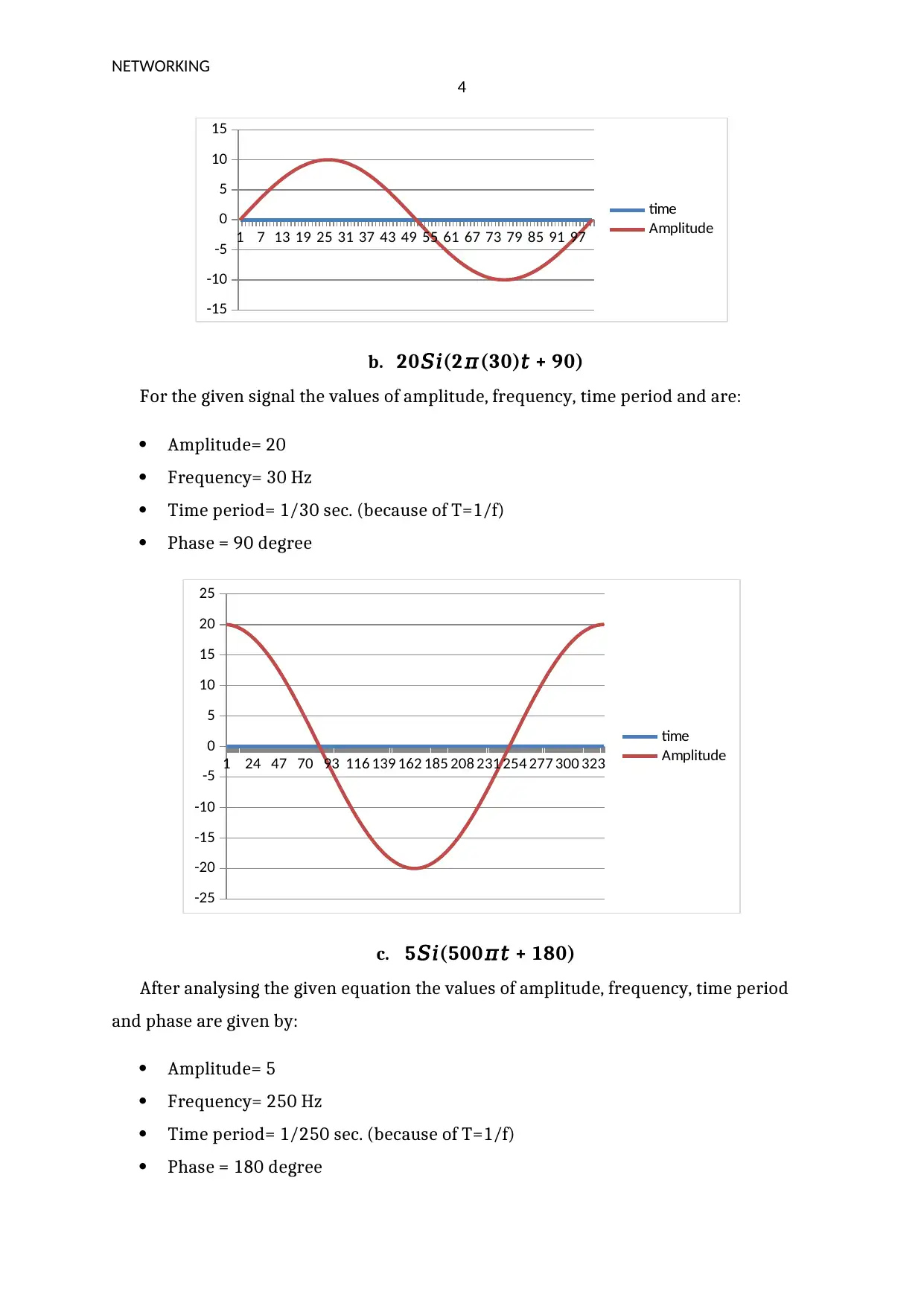
a. 10𝑆𝑖(2𝜋(100)𝑡)
It is observed that the standard equation of sin wave is given as:
X= a sin(2pift+phase)
After comparing the given equation with a standard equation the values of
amplitude, frequency, time period and phase are:
Amplitude= 10
Frequency= 100 Hz
Time period= 1/100 sec. (Here, the time period is inversely prepositional to the
frequency)
Phase = 0 degree
Secure Best Marks with AI Grader
Need help grading? Try our AI Grader for instant feedback on your assignments.
NETWORKING
4
1 7 13 19 25 31 37 43 49 55 61 67 73 79 85 91 97
-15
-10
-5
0
5
10
15
time
Amplitude
b. 20𝑆𝑖(2𝜋(30)𝑡 + 90)
For the given signal the values of amplitude, frequency, time period and are:
Amplitude= 20
Frequency= 30 Hz
Time period= 1/30 sec. (because of T=1/f)
Phase = 90 degree
1 24 47 70 93 116 139 162 185 208 231 254 277 300 323
-25
-20
-15
-10
-5
0
5
10
15
20
25
time
Amplitude
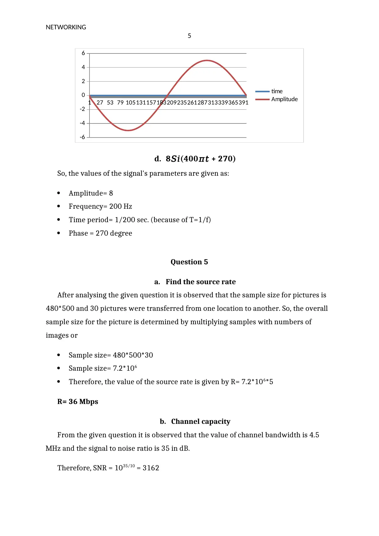
c. 5𝑆𝑖(500𝜋𝑡 + 180)
After analysing the given equation the values of amplitude, frequency, time period
and phase are given by:
Amplitude= 5
Frequency= 250 Hz
Time period= 1/250 sec. (because of T=1/f)
Phase = 180 degree
NETWORKING
5
1 27 53 79 105131157183209235261287313339365391
-6
-4
-2
0
2
4
6
time
Amplitude
d. 8𝑆𝑖(400𝜋𝑡 + 270)
So, the values of the signal's parameters are given as:
Amplitude= 8
Frequency= 200 Hz
Time period= 1/200 sec. (because of T=1/f)
Phase = 270 degree
Question 5
a. Find the source rate
After analysing the given question it is observed that the sample size for pictures is
480*500 and 30 pictures were transferred from one location to another. So, the overall
sample size for the picture is determined by multiplying samples with numbers of
images or
Sample size= 480*500*30
Sample size= 7.2*106
Therefore, the value of the source rate is given by R= 7.2*106*5
R= 36 Mbps
b. Channel capacity
From the given question it is observed that the value of channel bandwidth is 4.5
MHz and the signal to noise ratio is 35 in dB.
Therefore, SNR = 1035/10 = 3162
NETWORKING
6
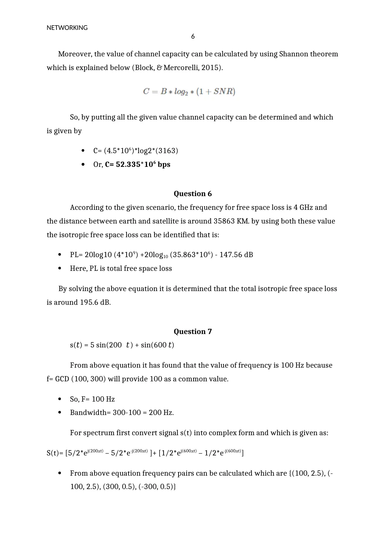
Moreover, the value of channel capacity can be calculated by using Shannon theorem
which is explained below (Block, & Mercorelli, 2015).
So, by putting all the given value channel capacity can be determined and which
is given by
C= (4.5*106)*log2*(3163)
Or, C= 52.335*106 bps
Question 6
According to the given scenario, the frequency for free space loss is 4 GHz and
the distance between earth and satellite is around 35863 KM. by using both these value
the isotropic free space loss can be identified that is:
PL= 20log10 (4*109) +20log10 (35.863*106) - 147.56 dB
Here, PL is total free space loss
By solving the above equation it is determined that the total isotropic free space loss
is around 195.6 dB.
Question 7
s(𝑡) = 5 sin(200𝜋 𝑡 ) + sin(600𝜋𝑡)
From above equation it has found that the value of frequency is 100 Hz because
f= GCD (100, 300) will provide 100 as a common value.
So, F= 100 Hz
Bandwidth= 300-100 = 200 Hz.
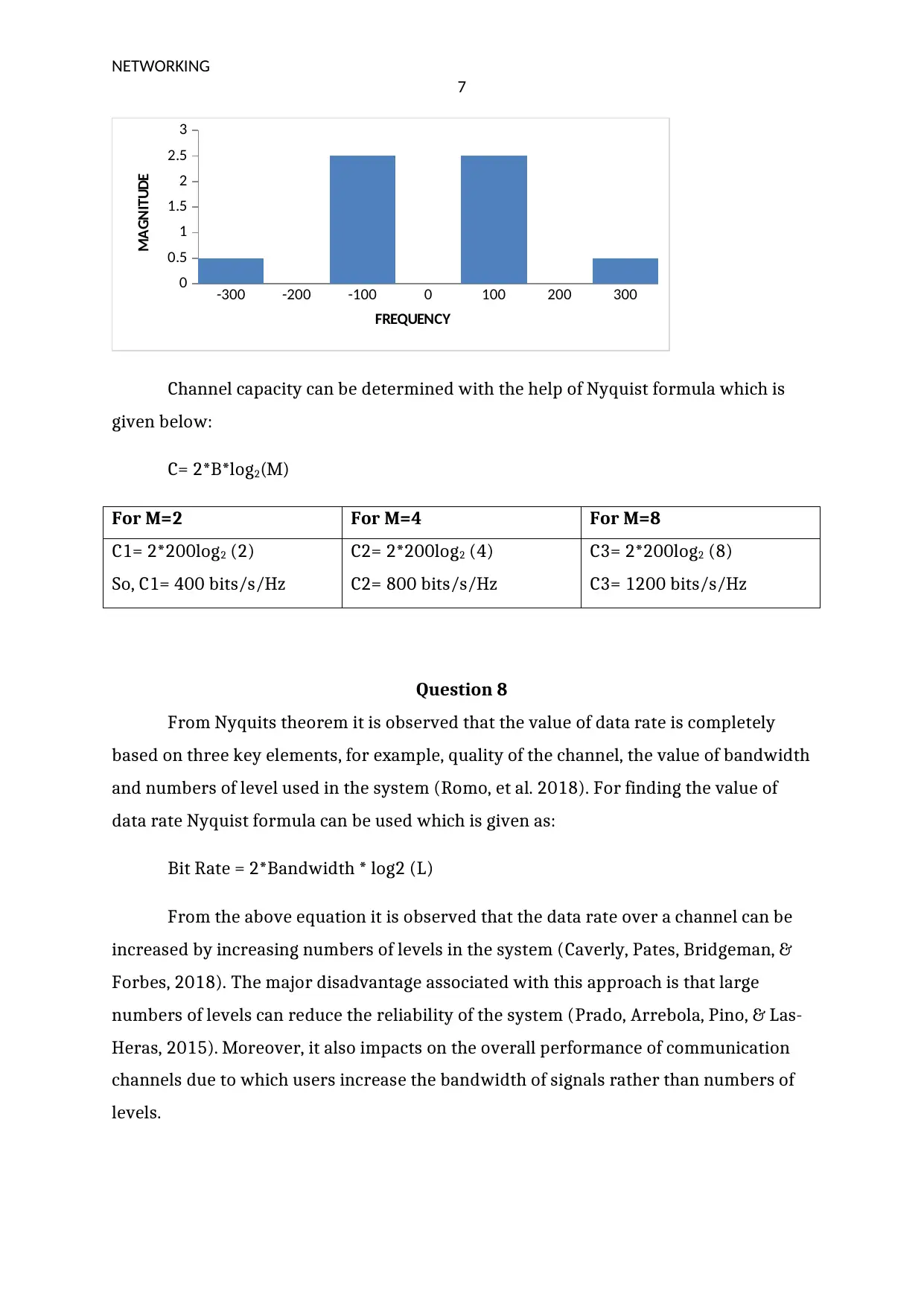
For spectrum first convert signal s(t) into complex form and which is given as:
S(t)= [5/2*ej(200t) – 5/2*e-j(200t) ]+ [1/2*ej(600t) – 1/2*e-j(600t)]
From above equation frequency pairs can be calculated which are {(100, 2.5), (-
100, 2.5), (300, 0.5), (-300, 0.5)}
Paraphrase This Document
Need a fresh take? Get an instant paraphrase of this document with our AI Paraphraser
NETWORKING
7
-300 -200 -100 0 100 200 300
0
0.5
1
1.5
2
2.5
3
FREQUENCY
MAGNITUDE
Channel capacity can be determined with the help of Nyquist formula which is
given below:
C= 2*B*log2(M)
For M=2 For M=4 For M=8
C1= 2*200log2 (2)
So, C1= 400 bits/s/Hz
C2= 2*200log2 (4)
C2= 800 bits/s/Hz
C3= 2*200log2 (8)
C3= 1200 bits/s/Hz
Question 8
From Nyquits theorem it is observed that the value of data rate is completely
based on three key elements, for example, quality of the channel, the value of bandwidth
and numbers of level used in the system (Romo, et al. 2018). For finding the value of
data rate Nyquist formula can be used which is given as:
Bit Rate = 2*Bandwidth * log2 (L)
From the above equation it is observed that the data rate over a channel can be
increased by increasing numbers of levels in the system (Caverly, Pates, Bridgeman, &
Forbes, 2018). The major disadvantage associated with this approach is that large
numbers of levels can reduce the reliability of the system (Prado, Arrebola, Pino, & Las-
Heras, 2015). Moreover, it also impacts on the overall performance of communication
channels due to which users increase the bandwidth of signals rather than numbers of
levels.
NETWORKING
8
Question 9
It is observed that circuit switching is a more reliable process rather than packet
switching which is one of the major differences between packet switching and circuit
switching (Saridis, et al., 2016). Another difference is that circuit switching requires a
physical path between source and destination but packet switching does not require
any physical path for communication (Porter, et al., 2013). Moreover, it is analysed that
the circuit switching the waste a huge amount of bandwidth but in the case of packet
switching system does not waste bandwidth. Circuit switching store the complete
bandwidth in advance but packet switching does not store any bandwidth for future
communication (Perelló, et al., 2013).
The major benefit of packet switching over circuit switching is that it does not
waste bandwidth due to which many consumers use this process in the communication
channels. Moreover, packet switching is more effective and efficient as compared to
circuit switching (McDonald, J. C. 2013).
Question 10
According to the provided case, it is observed that distance between antennas is
40 km and height of one antenna should be twice of the other antenna.
Suppose height of one antenna is H1 and another antenna is H2
So, H1 =2H2
Now, D= 3.57*sqrt (kH1+kH2)
By putting all values in the above equation height of antennas can be determined
and which is given as:
40= 3.57*1.1547(sqrt(3H2))
Or, H2= 31.6 meters
H1= 63.3 meters.
NETWORKING
9
References
Block, B. M., & Mercorelli, P. (2015). Conceptual understanding of complex components
and Nyquist-Shannon sampling theorem: A design based research in
Engineering. In 2015 IEEE Global Engineering Education Conference (EDUCON),
12(2), 462-470.
Caverly, R. J., Pates, R., Bridgeman, L. J., & Forbes, J. R. (2018). MIMO Nyquist
interpretation of the large gain theorem. International Journal of Control, 1-10.
McDonald, J. C. (Ed.). (2013). Fundamentals of digital switching. Springer Science &
Business Media.
Perelló, J., Spadaro, S., Ricciardi, S., Careglio, D., Peng, S., Nejabati, R., ... & Dorren, H. J.
(2013). All-optical packet/circuit switching-based data centre network for
enhanced scalability, latency, and throughput. IEEE Network, 27(6), 14-22.
Porter, G., Strong, R., Farrington, N., Forencich, A., Chen-Sun, P., Rosing, T., ... & Vahdat, A.
(2013). Integrating microsecond circuit switching into the data centre (Vol. 43,
No. 4, pp. 447-458). ACM.
Prado, D. R., Arrebola, M., Pino, M. R., & Las-Heras, F. (2015). An efficient calculation of
the far field radiated by non-uniformly sampled planar fields complying Nyquist
theorem. IEEE Transactions on Antennas and Propagation, 63(2), 862-865.
Romo-Cárdenas, G., Avilés-Rodríguez, G. J., Sánchez-López, J. D. D., Cosío-León, M.,
Luque, P. A., Gómez-Gutiérrez, C. M., ... & Navarro-Cota, C. X. (2018). Nyquist-
Shannon theorem application for Savitzky-Golay smoothing window size
parameter determination in bio-optical signals. Results in Physics, 11, 17-22.
Saridis, G. M., Peng, S., Yan, Y., Aguado, A., Guo, B., Arslan, M., ... & Spadaro, S. (2016).
Lightness: A function-virtualizable software-defined data centre network with
all-optical circuit/packet switching. Journal of Lightwave Technology, 34(7),
1618-1627.
1 out of 10
Related Documents
Your All-in-One AI-Powered Toolkit for Academic Success.
+13062052269
info@desklib.com
Available 24*7 on WhatsApp / Email
![[object Object]](/_next/static/media/star-bottom.7253800d.svg)
Unlock your academic potential
© 2024 | Zucol Services PVT LTD | All rights reserved.


