ProductsLogo
LogoStudy Documents
LogoAI Grader
LogoAI Answer
LogoAI Code Checker
LogoPlagiarism Checker
LogoAI Paraphraser
LogoAI Quiz
LogoAI Detector
PricingBlogAbout Us
logo

NIT3104 Computer Architecture Part A DESIGNING A DIGITAL TIMER

Verified

Added on  2023/04/03

|2
|202
|104
AI Summary
hi ther einside the pdf file you can see that part A is due on 5/27/2019 and part B is due on 06/03/2019 and i hope you guys will follow the given instruction thank you. and the weight of this both part A and B is 25% thanks.

Contribute Materials

Your contribution can guide someone’s learning journey. Share your documents today.
Document Page
NIT3104 Computer Architecture
Part A
DESIGNING A DIGITAL TIMER COMPUTER
Student Name:
Student ID:

Secure Best Marks with AI Grader

Need help grading? Try our AI Grader for instant feedback on your assignments.
Document Page
Introduction:
Timer is a pulse counting circuit which increments on each pulse. The time unit
counted depends upon the pulse input frequency. If frequency is managed at
1Hz it becomes a clock timer which can count seconds, minutes and hours.
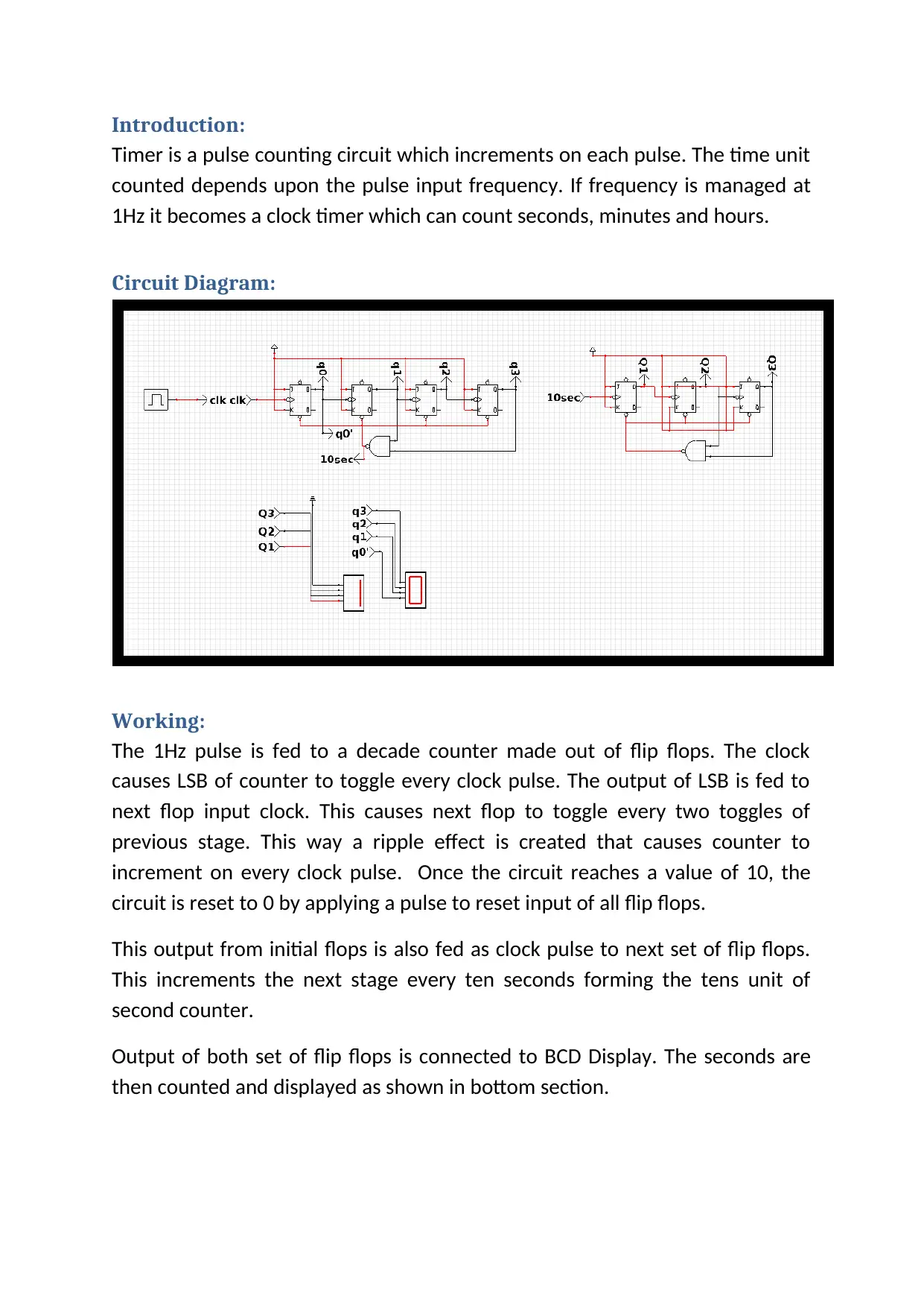
Circuit Diagram:
Working:
The 1Hz pulse is fed to a decade counter made out of flip flops. The clock
causes LSB of counter to toggle every clock pulse. The output of LSB is fed to
next flop input clock. This causes next flop to toggle every two toggles of
previous stage. This way a ripple effect is created that causes counter to
increment on every clock pulse. Once the circuit reaches a value of 10, the
circuit is reset to 0 by applying a pulse to reset input of all flip flops.
This output from initial flops is also fed as clock pulse to next set of flip flops.
This increments the next stage every ten seconds forming the tens unit of
second counter.
Output of both set of flip flops is connected to BCD Display. The seconds are
then counted and displayed as shown in bottom section.
1 out of 2
[object Object]

Your All-in-One AI-Powered Toolkit for Academic Success.

Available 24*7 on WhatsApp / Email

[object Object]