Comprehensive Report: Database Normalization and ER Diagram Analysis
VerifiedAdded on 2021/02/20
|11
|1160
|139
Report
AI Summary
This report provides a comprehensive overview of database normalization, a crucial process for organizing data in relational databases. It begins by defining normalization and its importance in controlling data redundancies and eliminating anomalies. The report then delves into the different normal forms (1NF, 2NF, 3NF) and explains the concept of dependency diagrams, illustrating how they help visualize relationships between attributes. It also covers multivalued dependencies and demonstrates how to create dependency graphs to structure database tables. Furthermore, the report includes an Entity-Relationship (ER) diagram, which graphically represents the entities and their relationships within the database. The report concludes with a summary of the key concepts and references relevant literature, providing a solid foundation for understanding database design principles. The report provides practical examples and diagrams to enhance understanding of the concepts. The report is perfect for students studying database management and data science.

NORMALISATION
Paraphrase This Document
Need a fresh take? Get an instant paraphrase of this document with our AI Paraphraser
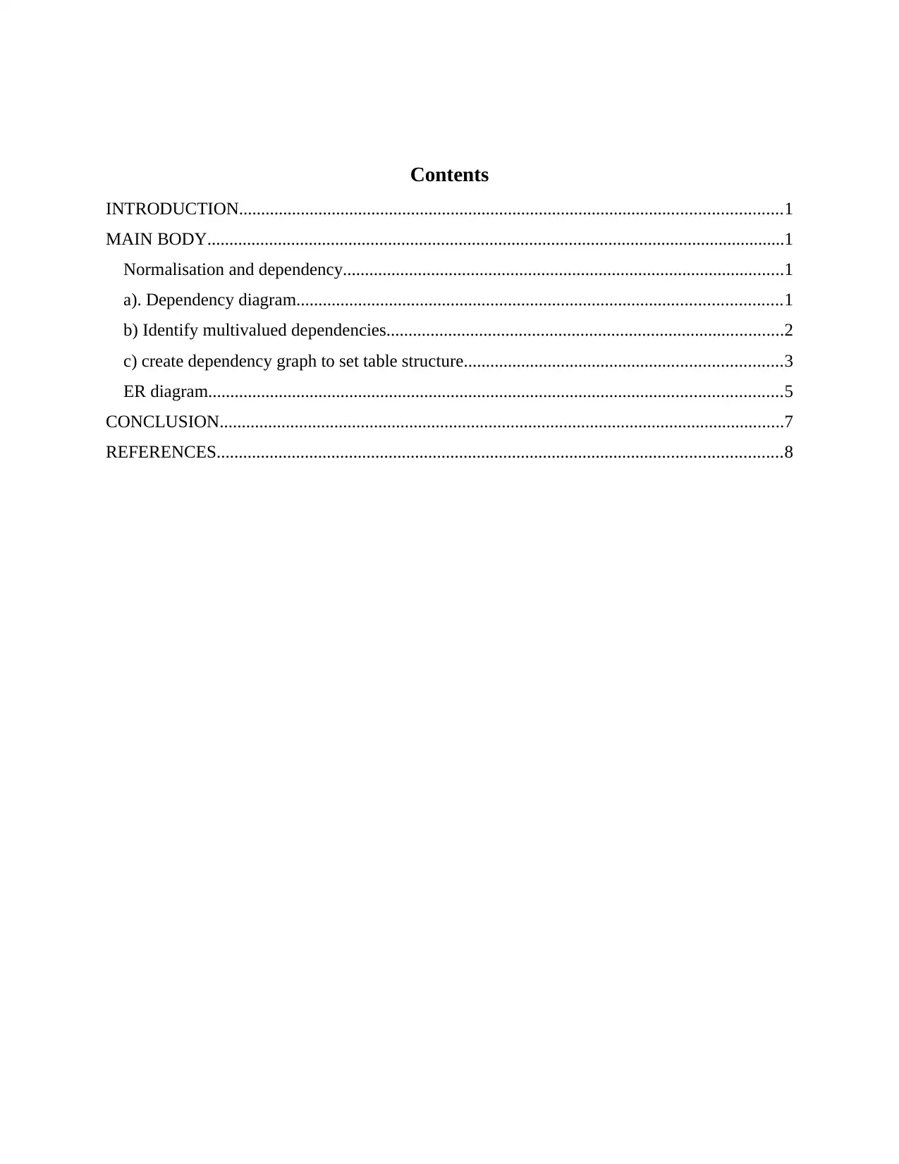
Contents
INTRODUCTION...........................................................................................................................1
MAIN BODY...................................................................................................................................1
Normalisation and dependency....................................................................................................1
a). Dependency diagram..............................................................................................................1
b) Identify multivalued dependencies..........................................................................................2
c) create dependency graph to set table structure........................................................................3
ER diagram..................................................................................................................................5
CONCLUSION................................................................................................................................7
REFERENCES................................................................................................................................8
INTRODUCTION
Normalisation can be defined as a formal process that helps in assigning all the present
attributes to all the present entities. In this assignment dependency diagram, multivalued
dependency and crow's foot ER diagram will be explained in detail.
MAIN BODY
Normalisation and dependency
Normalisation is a process of organising data into database. It also helps in controlling
data redundancies from relations or set of relations (Chitti, Murkin and Chitchyan, 2019). It also
helps in eliminating undesirable data anomalies where data upgrading, insertion, deletion can
destroy the overall integrity of the data.
There are four main types of normalisation form: 1NF, 2NF, 3NF and BCNF. If relation consist
of atomic value then it is in 1NF. If relation is in 1NF and all the non key attributes are fully
functional and dependent on primary key, then the relation is in 2NF. If the current relation is
already in 2NF and there is no transition dependency that exist then the relation is in 3NF.
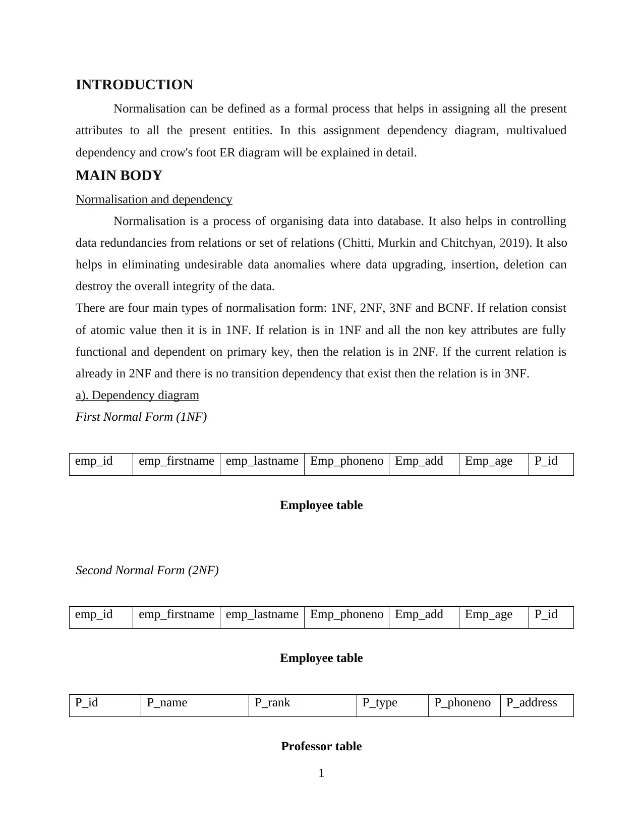
a). Dependency diagram
First Normal Form (1NF)
emp_id emp_firstname emp_lastname Emp_phoneno Emp_add Emp_age P_id
Employee table
Second Normal Form (2NF)
emp_id emp_firstname emp_lastname Emp_phoneno Emp_add Emp_age P_id
Employee table
P_id P_name P_rank P_type P_phoneno P_address
Professor table
1
⊘ This is a preview!⊘
Do you want full access?
Subscribe today to unlock all pages.

Trusted by 1+ million students worldwide
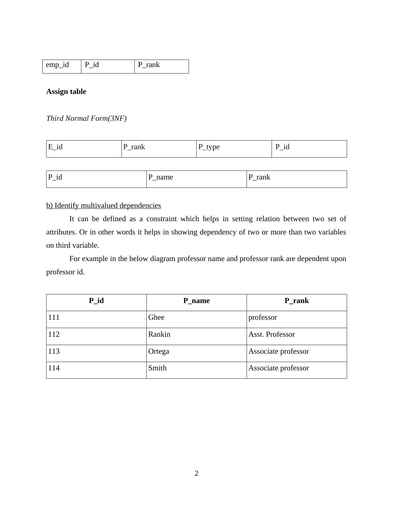
emp_id P_id P_rank
Assign table
Third Normal Form(3NF)
E_id P_rank P_type P_id
P_id P_name P_rank
b) Identify multivalued dependencies
It can be defined as a constraint which helps in setting relation between two set of
attributes. Or in other words it helps in showing dependency of two or more than two variables
on third variable.
For example in the below diagram professor name and professor rank are dependent upon
professor id.
P_id P_name P_rank
111 Ghee professor
112 Rankin Asst. Professor
113 Ortega Associate professor
114 Smith Associate professor
2
Paraphrase This Document
Need a fresh take? Get an instant paraphrase of this document with our AI Paraphraser
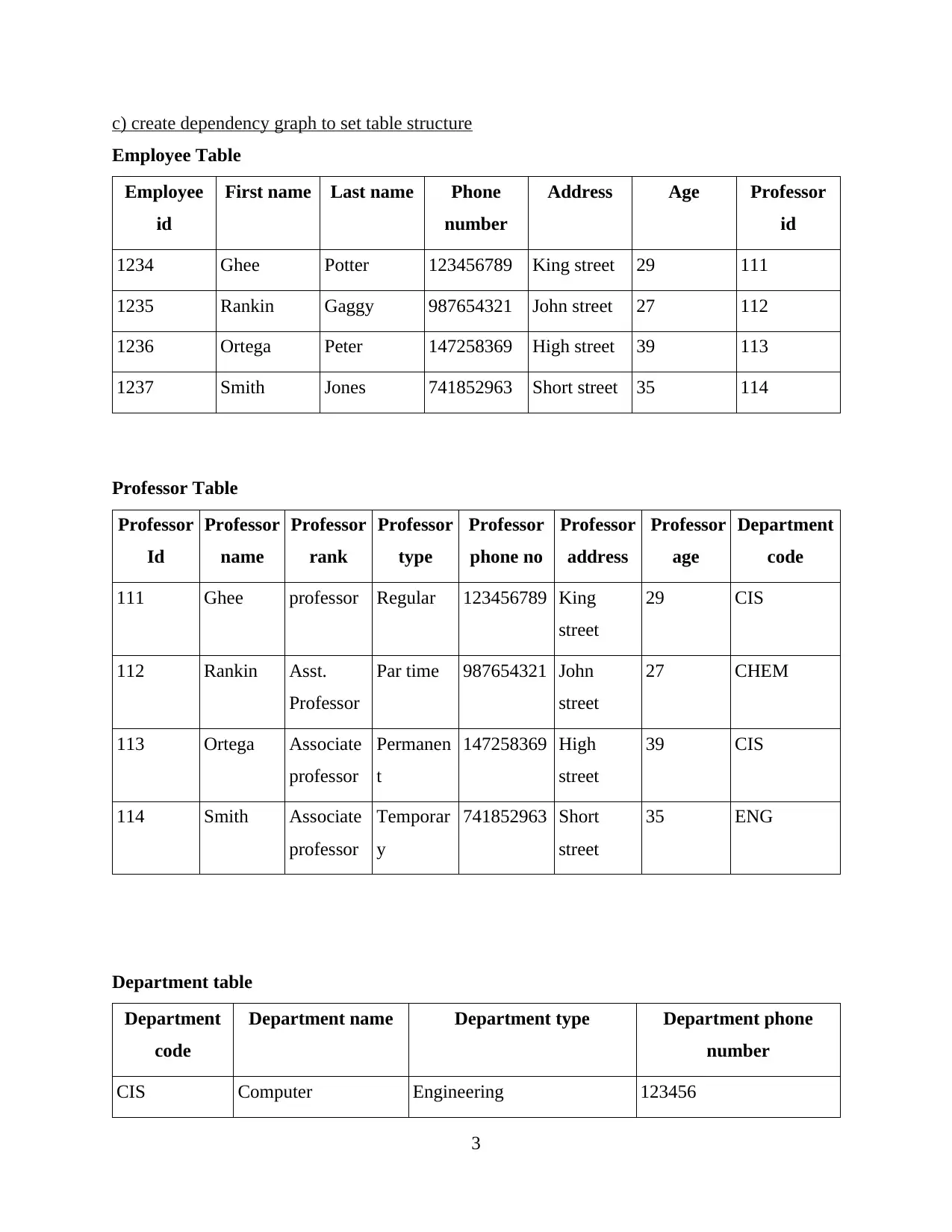
c) create dependency graph to set table structure
Employee Table
Employee
id
First name Last name Phone
number
Address Age Professor
id
1234 Ghee Potter 123456789 King street 29 111
1235 Rankin Gaggy 987654321 John street 27 112
1236 Ortega Peter 147258369 High street 39 113
1237 Smith Jones 741852963 Short street 35 114
Professor Table
Professor
Id
Professor
name
Professor
rank
Professor
type
Professor
phone no
Professor
address
Professor
age
Department
code
111 Ghee professor Regular 123456789 King
street
29 CIS
112 Rankin Asst.
Professor
Par time 987654321 John
street
27 CHEM
113 Ortega Associate
professor
Permanen
t
147258369 High
street
39 CIS
114 Smith Associate
professor
Temporar
y
741852963 Short
street
35 ENG
Department table
Department
code
Department name Department type Department phone
number
CIS Computer Engineering 123456
3
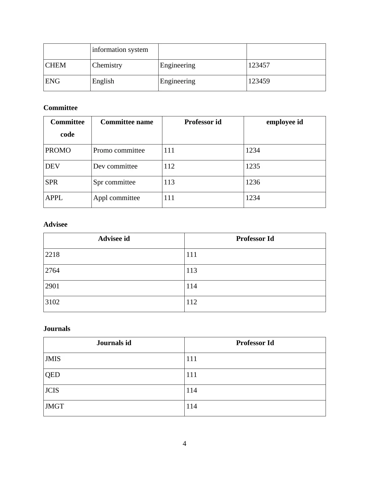
information system
CHEM Chemistry Engineering 123457
ENG English Engineering 123459
Committee
Committee
code
Committee name Professor id employee id
PROMO Promo committee 111 1234
DEV Dev committee 112 1235
SPR Spr committee 113 1236
APPL Appl committee 111 1234
Advisee
Advisee id Professor Id
2218 111
2764 113
2901 114
3102 112
Journals
Journals id Professor Id
JMIS 111
QED 111
JCIS 114
JMGT 114
4
⊘ This is a preview!⊘
Do you want full access?
Subscribe today to unlock all pages.

Trusted by 1+ million students worldwide
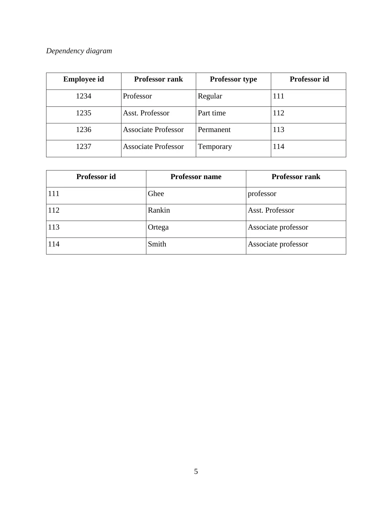
Dependency diagram
Employee id Professor rank Professor type Professor id
1234 Professor Regular 111
1235 Asst. Professor Part time 112
1236 Associate Professor Permanent 113
1237 Associate Professor Temporary 114
Professor id Professor name Professor rank
111 Ghee professor
112 Rankin Asst. Professor
113 Ortega Associate professor
114 Smith Associate professor
5
Paraphrase This Document
Need a fresh take? Get an instant paraphrase of this document with our AI Paraphraser
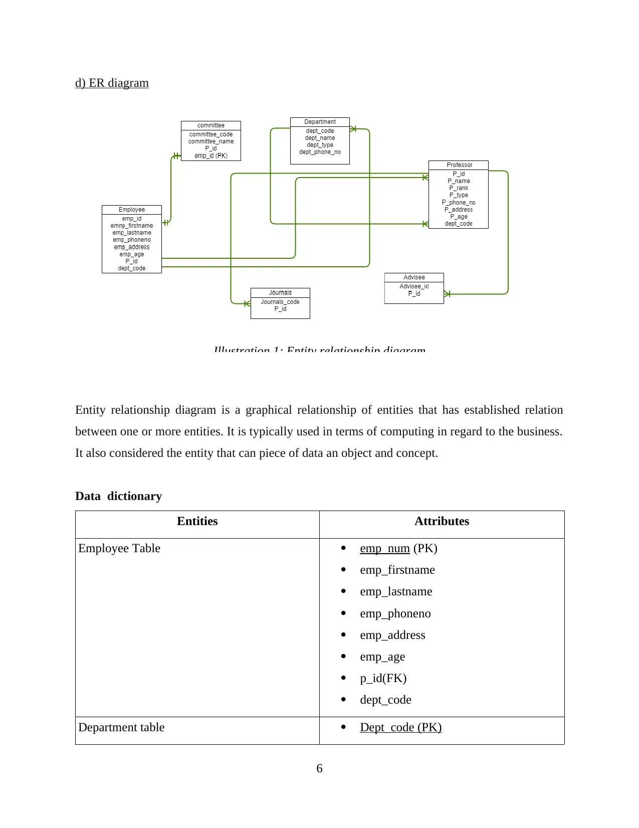
d) ER diagram
Entity relationship diagram is a graphical relationship of entities that has established relation
between one or more entities. It is typically used in terms of computing in regard to the business.
It also considered the entity that can piece of data an object and concept.
Data dictionary
Entities Attributes
Employee Table emp_num (PK)
emp_firstname
emp_lastname
emp_phoneno
emp_address
emp_age
p_id(FK)
dept_code
Department table Dept_code (PK)
6
Illustration 1: Entity relationship diagram
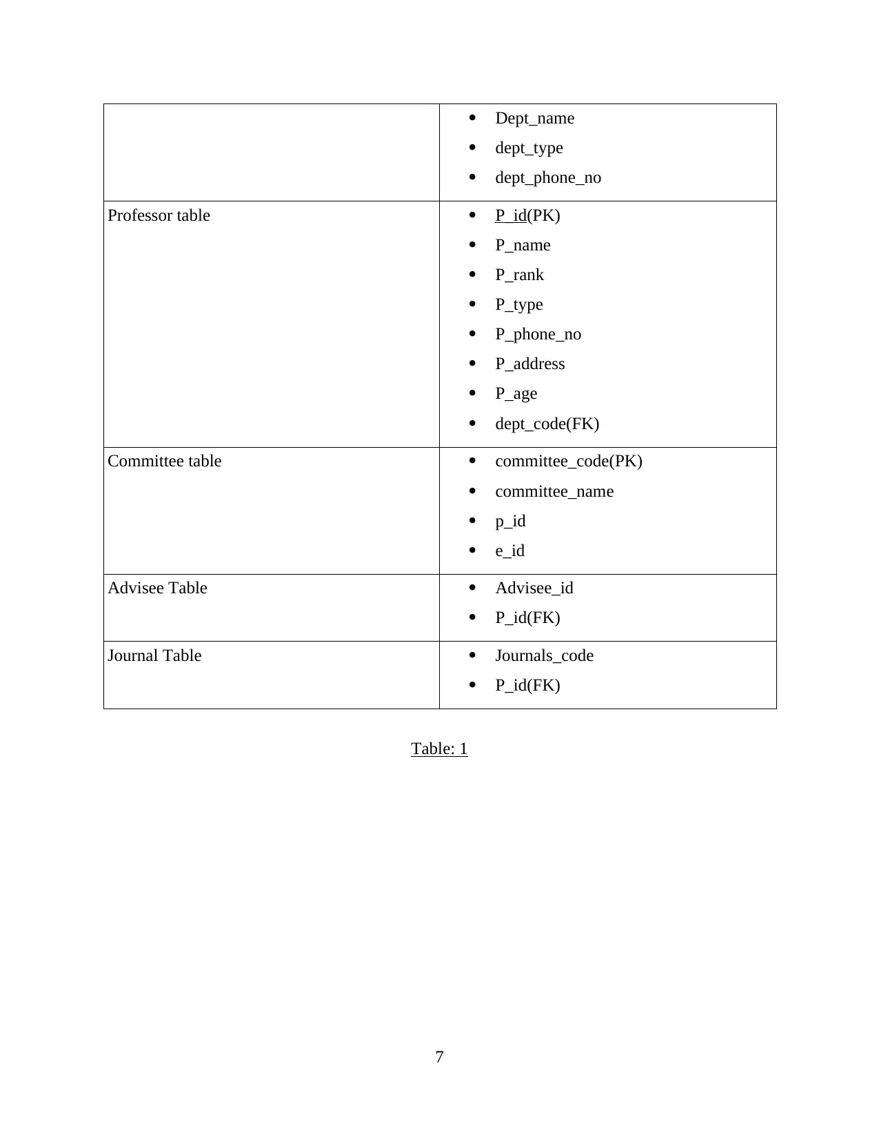
Dept_name
dept_type
dept_phone_no
Professor table P_id(PK)
P_name
P_rank
P_type
P_phone_no
P_address
P_age
dept_code(FK)
Committee table committee_code(PK)
committee_name
p_id
e_id
Advisee Table Advisee_id
P_id(FK)
Journal Table Journals_code
P_id(FK)
Table: 1
7
dept_type
dept_phone_no
Professor table P_id(PK)
P_name
P_rank
P_type
P_phone_no
P_address
P_age
dept_code(FK)
Committee table committee_code(PK)
committee_name
p_id
e_id
Advisee Table Advisee_id
P_id(FK)
Journal Table Journals_code
P_id(FK)
Table: 1
7
⊘ This is a preview!⊘
Do you want full access?
Subscribe today to unlock all pages.

Trusted by 1+ million students worldwide

CONCLUSION
Above discussion successfully identified normalisation process like 1NF, 2NF and 3NF
and it has also been identified that ER model represents as an entity relationship. Furthermore,
This assignment helps in defining dependencies between different tables.
8
Above discussion successfully identified normalisation process like 1NF, 2NF and 3NF
and it has also been identified that ER model represents as an entity relationship. Furthermore,
This assignment helps in defining dependencies between different tables.
8
Paraphrase This Document
Need a fresh take? Get an instant paraphrase of this document with our AI Paraphraser
REFERENCES
Books and Journals
Chitti, P., Murkin, J. and Chitchyan, R., 2019, June. Data Management: Relational vs Blockchain
Databases. In International Conference on Advanced Information Systems
Engineering (pp. 189-200). Springer, Cham.
Fredstam, M. and Johansson, G., 2019. Comparing database management systems with
SQLAlchemy: A quantitative study on database management systems.
Mackenzie, M. and et.al., 2019. What might Normalisation Process Theory bring to policy
implementation studies? Learning lessons and uncovering questions through a case study
of the profound implementation failure of a new policing policy. Social Policy &
Administration. 53(3). pp.449-463.
9
1 out of 11
Your All-in-One AI-Powered Toolkit for Academic Success.
+13062052269
info@desklib.com
Available 24*7 on WhatsApp / Email
![[object Object]](/_next/static/media/star-bottom.7253800d.svg)
Unlock your academic potential
Copyright © 2020–2025 A2Z Services. All Rights Reserved. Developed and managed by ZUCOL.