CFD Analysis of flow inside nozzle and aerodynamic flow over NACA 2415 aerofoil 2022
Added on 2022-09-15
32 Pages2928 Words24 Views
CFD Analysis of flow inside nozzle and
aerodynamic flow over NACA 2415 aerofoil
<Student Name>
<Student Number>
Assignment Report
Supervisor: <XXX>
Faculty of Science and Engineering
University Of Wolverhampton
<Month Year>
aerodynamic flow over NACA 2415 aerofoil
<Student Name>
<Student Number>
Assignment Report
Supervisor: <XXX>
Faculty of Science and Engineering
University Of Wolverhampton
<Month Year>
TABLE OF CONTENTS
TABLE OF CONTENTS..................................................................................................................i
Task 1 – Converging Nozzle – Flow analysis using Solidworks.....................................................1
Task 1a. Computational Fluid Dynamics (2D) Model of Converging Nozzle using Solidworks
with different inlet pressure values..............................................................................................1
Task 1b. Results in the form of velocity, pressure and density inside the nozzle........................8
Task 1c. Effect of variation of Outlet pressure variation onto the outlet velocity profile using
2D CFD simulation in Solidworks keeping the inlet velocity profile constant.........................10
Task 1d. Validation of obtained results with analytical calculations.........................................12
CHAPTER II: Task 2 – CFD Analysis of Flow around a Aerofoil wing......................................14
Task 2a. Using ANSYS FLUNET tool, create a 2D- CFD model for the flow around the
aerofoil when the wing is 4-degree angle of attack with the use of Spalart - Allmaras viscous
model..........................................................................................................................................14
Task 2b. Using the CFD model to determine the drag and lift coefficients (CD and CL) of the
aerofoil at three different of angles of attack including 4º, 8º and 12º. Discuss critically the
influence of angle of attack on the lift and drag coefficients and overall aerodynamic
behaviour of the wing. Support your discussion with suitable plots and graphs.......................22
Task 2c. Comparison with Aerofoil performance data for NACA2415 Aerofoil......................27
Task 2d. Assuming that the flow velocity is increased to 420m/sec, create caved model for the
flow around the aerofoil when the angle of attack is 4 degree. Plot velocity, pressure, Mach
number, and density contours around the wing. Explain your observations and discuss
critically how the new flow velocity affects the aerodynamic behaviour of the wing..............28
i
Task 1 – Converging Nozzle – Flow analysis using Solidworks
Converging nozzle are used at many testing equipment as well as at many industrial component
where balance between pressure and velocity is to be established. Flow inside a nozzle can be
analytically calculated by the mass conservation principals. The total volume which enters from
one end has to come out from other end. By using this principal, the bigger area at low velocity at
entry of nozzle can be related to smaller area and higher velocity at other end of the nozzle. In
this analysis, a convergent nozzle is designed with a contraction ratio of 36:1. Designed nozzle is
analysed using computational fluid dynamics method in ANSYS fluent to assess their flow
behaviour and variation of outlet velocity and pressure with variation in inlet pressure. The
temperature inside the nozzle is considered 293K only.
Task 1a. Computational Fluid Dynamics (2D) Model of Converging
Nozzle using Solidworks with different inlet pressure values
A convergent nozzle has been modelled in Solidworks which has a contraction ratio of 36:1 as
shown in Figure 1. To obtain the dimensions :1of the nozzle, its inlet diameter is assumed and
based on the calculations shown below, outlet diameter can be calculation taking the contraction
ratio as 36:1.
To design a nozzle with given contraction ratio of 36:1, we can calculate the diameter ratio for
the nozzle.
A2
A1
=
πD 2
2
4
π D1
2
4
=D2= 1
36 then D2= D1
6 → D2= D1
6 if D2=25 cm ,
then we can get D1=25∗6=150 cm .
We have chosen the length 250 cm. Since A2/A1 = 36/1 hence D2/D1 = 6/1 hence D2 = 6D1
For the current case, D2 is taken as 25 mm hence D1 = 150 mm. The final modelled geometry is
shown in figure 2 with both the diameters and length of the nozzle.
Once the model geometry has been setup, Solidworks wizard for setting up computational fluid
dynamics model is used for which every input is described in this section. Figure 3 shows the
unit system which is chosen as SI for all the field variable and input variable of the analysis.
Figure 4 shows the type of analysis chosen as ‘Internal’ in Solidworks meaning the flow would
be internal to the cavity. Since the analysis is to be performed with Air as the fluid material, it is
chosen in Solidworks wizard as shown in figure 5. The wall conditions are defined as shown in
figure 6 as adiabatic walls with no roughness. The last input required for the wizard is initial
conditions in which atmospheric pressure and room temperature is defined with initial velocities
to be all zero as shown in figure 7. This finishes the wizard and gives a computational domain
over the region of analysis as shown in figure 8.
1
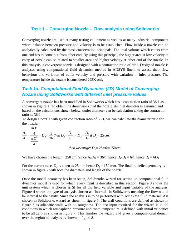
Figure 1: Converging nozzle which is to be designed and analysed using Solidworks
Figure 2: Sketch and 3D shape of Converging Nozzle as created in Solidworks with Calculated
dimensions
2
Figure 2: Sketch and 3D shape of Converging Nozzle as created in Solidworks with Calculated
dimensions
2
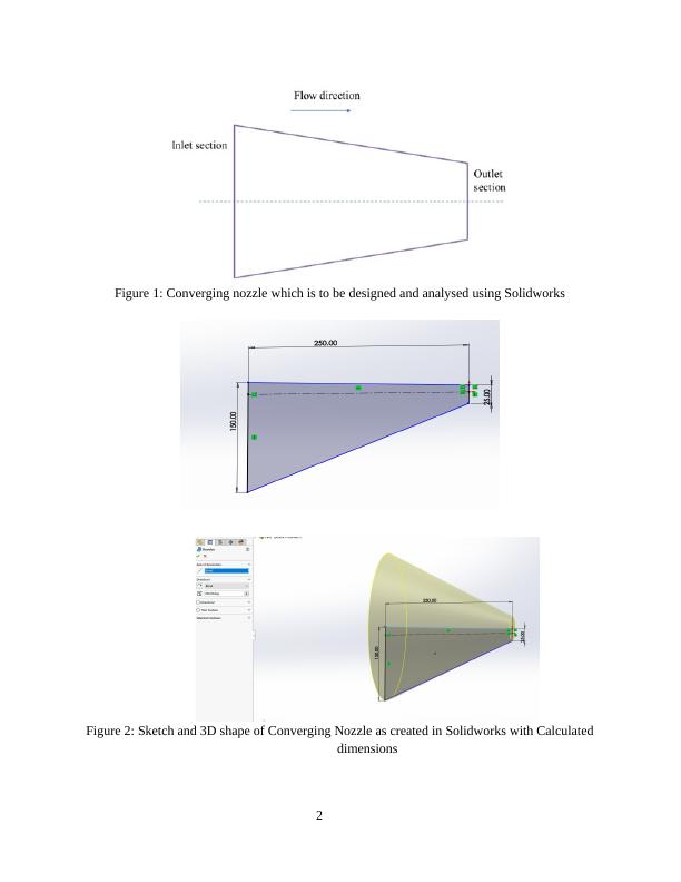
Figure 3: Present unit system selection for each of the parameters in flow simulation of
Solidworks
Figure 4: Type of analysis selected as ‘Internal’ in flow simulation of Solidworks
3
Solidworks
Figure 4: Type of analysis selected as ‘Internal’ in flow simulation of Solidworks
3
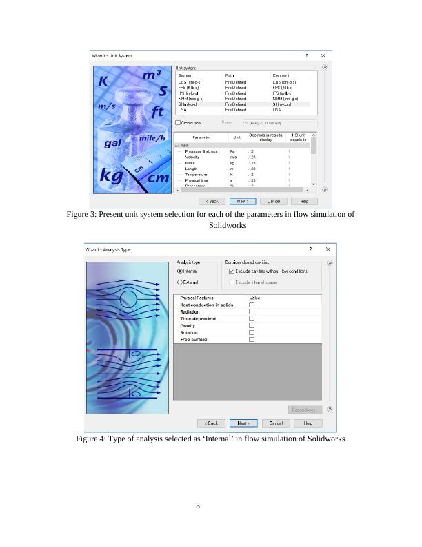
Figure 5: Working fluid selected to flow in the analysis is (Air)
Figure 6: Type of wall conditions as selected for flow analysis in Solidworks
4
Figure 6: Type of wall conditions as selected for flow analysis in Solidworks
4
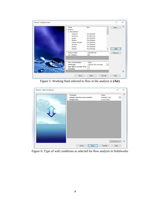
Figure 7: Type of Initial conditions as selected for flow analysis in Solidworks
Figure 8: Type of Computational domain containing the nozzle selected as 2D for flow analysis
in Solidworks
5
Figure 8: Type of Computational domain containing the nozzle selected as 2D for flow analysis
in Solidworks
5
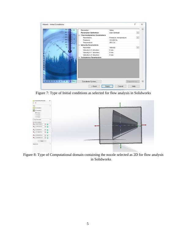
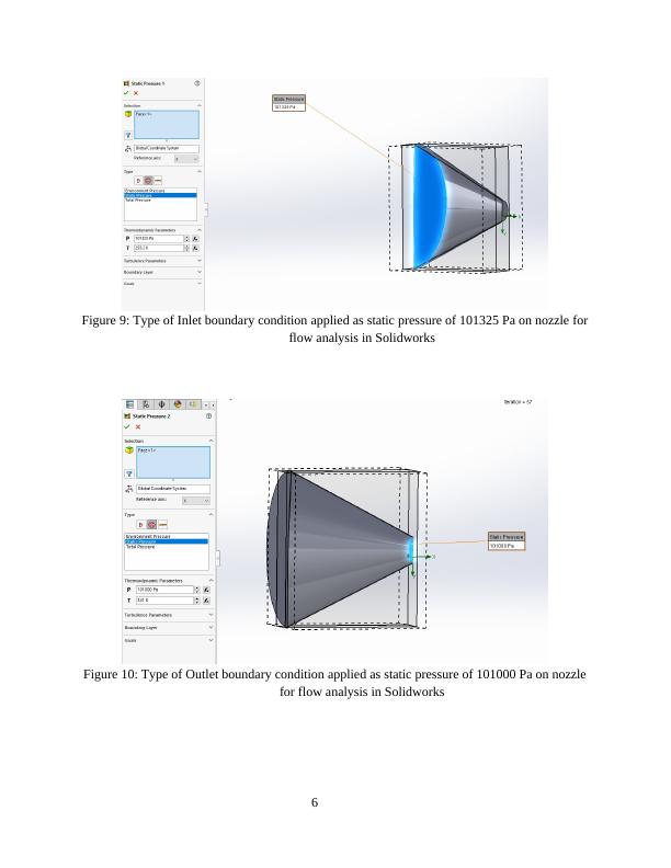
Figure 9: Type of Inlet boundary condition applied as static pressure of 101325 Pa on nozzle for
flow analysis in Solidworks
Figure 10: Type of Outlet boundary condition applied as static pressure of 101000 Pa on nozzle
for flow analysis in Solidworks
6
flow analysis in Solidworks
Figure 10: Type of Outlet boundary condition applied as static pressure of 101000 Pa on nozzle
for flow analysis in Solidworks
6
End of preview
Want to access all the pages? Upload your documents or become a member.
Related Documents
Study and Investigate the Flow of Airlg...
|17
|4047
|12
Simulation of Flow Past Cylinder at Moderate Reynolds Numbers: CFD Analysis and Resultslg...
|11
|1939
|255
Advanced Flow Modelling using Computational Fluid Dynamics (CFD)lg...
|19
|2851
|196
Simulation of Flow of Fluid in Hot and Cold Pipelg...
|14
|1475
|211