Detailed Analysis of Nozzles and Diffusers: Applications Report
VerifiedAdded on 2023/06/10
|23
|4581
|151
Report
AI Summary
This report provides a detailed analysis of nozzles and diffusers, crucial components in thermodynamics and mechanical engineering. It begins with an abstract and introduction, defining the objectives and scope of the research. The report then outlines the project, explaining the function of nozzles in controlling fluid flow, increasing velocity, and decreasing pressure. It differentiates between convergent and divergent nozzles and discusses their applications in jet engines, gas stoves, and carburetors. The report also delves into the function of diffusers, which reduce velocity and increase static pressure, and explores their use in centrifugal and axial flow compressors, as well as ramming of air in aircraft. Applications of nozzles in aircraft are also discussed. The report includes calculations related to fluid flow and provides examples of industrial applications. Various sources are cited throughout the report to support the information presented.
NAME OF THE STUDENT
NAME OF THE PROFESSOR
CITY/STATE
DATE/MONTH/YEAR
NAME OF THE PROFESSOR
CITY/STATE
DATE/MONTH/YEAR
Paraphrase This Document
Need a fresh take? Get an instant paraphrase of this document with our AI Paraphraser
1. Abstract
This paper presents the meaning of diffusers and nozzles in details as used in thermodynamics.
Various application of nozzles such as water turbines, jet engines, steam turbines, flow
measurement and those of diffusers such as in axial compressors, centrifugal compressors, and
ramming of air are discussed in this paper.
2. Introduction
2.1. Background
In the year 1960, a bed load sampler was developed by the California District and these samples
were the pressure differential type and they consisted of the nozzle having a larger cross-
section opening at the rear of the nozzle than at the entrance. This enabled the acceleration of
the flow as it passes into the nozzle.
2.2. Objective
This research discusses the nozzles and the diffusers into detail with various types of nozzles
and diffusers. The calculations involving the fluid flow are also included in the paper and lastly
the various applications of nozzles and diffusers.
2.3. Scope
The scope of the research project entails the applications of diffusers for example in axial and
centrifugal compressors and also the applications of nozzles in various industrial application s
and other sectors which they are helpful.
3. Project Outline
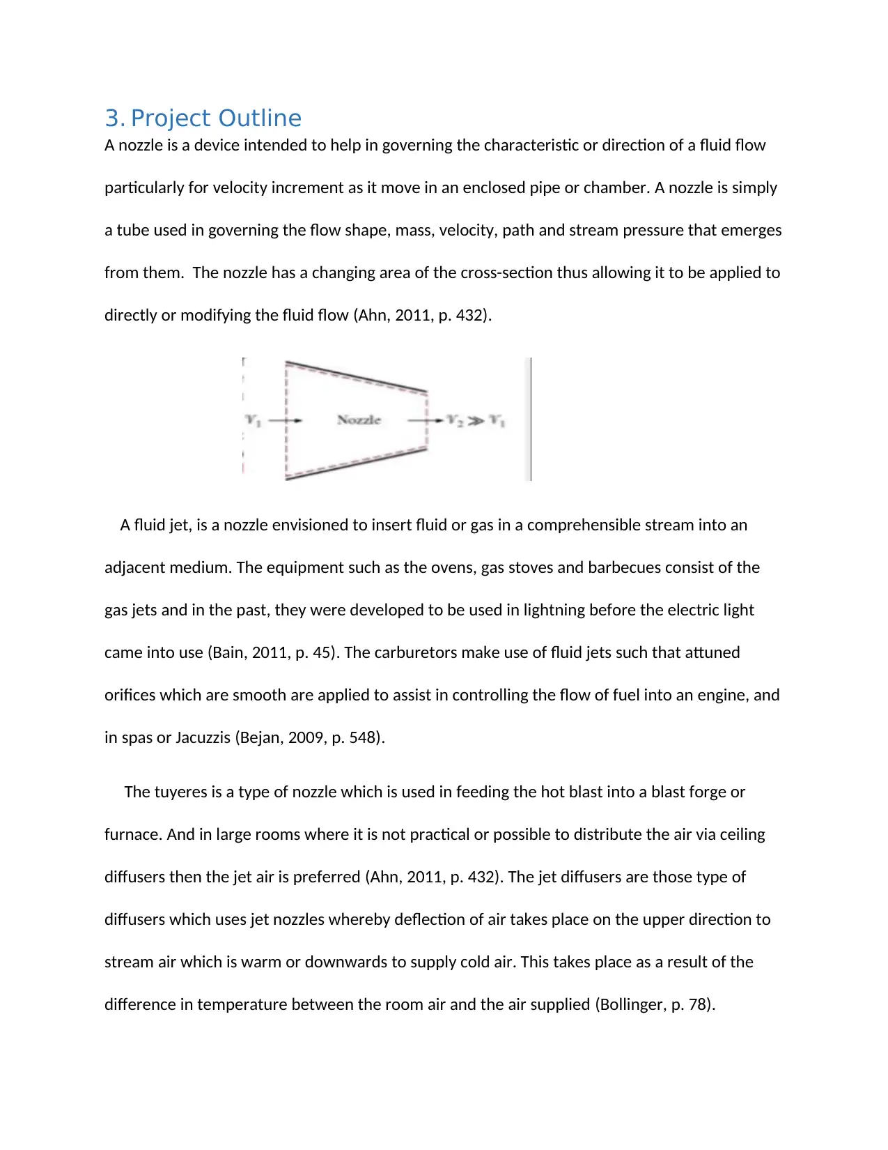
A nozzle is a device intended to help in governing the characteristic or direction of a fluid flow
particularly for velocity increment as it move in an enclosed pipe or chamber. A nozzle is simply
a tube used in governing the flow shape, mass, velocity, path and stream pressure that emerges
from them. The nozzle has a changing area of the cross-section thus allowing it to be applied to
directly or modifying the fluid flow (Ahn, 2011, p. 432).
A fluid jet, is a nozzle envisioned to insert fluid or gas in a comprehensible stream into an
adjacent medium. The equipment such as the ovens, gas stoves and barbecues consist of the
gas jets and in the past, they were developed to be used in lightning before the electric light
came into use (Bain, 2011, p. 45). The carburetors make use of fluid jets such that attuned
orifices which are smooth are applied to assist in controlling the flow of fuel into an engine, and
in spas or Jacuzzis (Bejan, 2009, p. 548).
The tuyeres is a type of nozzle which is used in feeding the hot blast into a blast forge or
furnace. And in large rooms where it is not practical or possible to distribute the air via ceiling
diffusers then the jet air is preferred (Ahn, 2011, p. 432). The jet diffusers are those type of
diffusers which uses jet nozzles whereby deflection of air takes place on the upper direction to
stream air which is warm or downwards to supply cold air. This takes place as a result of the
difference in temperature between the room air and the air supplied (Bollinger, p. 78).
⊘ This is a preview!⊘
Do you want full access?
Subscribe today to unlock all pages.

Trusted by 1+ million students worldwide
The nozzle aims at increasing the kinetic energy of the flowing medium at the expense of its
internal energy and pressure. The convergent and divergent are the best terms which can be
used in describing the nozzles. And convergent simply means lessening down from a wide
diameter to a smaller diameter in the flow direction while divergent involves expanding from a
smaller diameter to a larger one (Demirel, 2013, p. 219).
The subsonic fluids are accelerated by the by divergent nozzles but the fluid is slowed if the
flow is subsonic. The gases direction of escape is directly backward since thrust would not be
contributed to by the sideways component. This achieved by the shape of the divergent section
(Duncan, 2010, p. 65).
The needed energy from the combusting fuel which is supplemented to the initiated air allows
the jet exhaust to produce a net thrust. The passing of warm air through a high-speed nozzle, a
thrusting nozzle which immensely upsurges its kinetic energy. A thrust of a certain mass flow is
increased by an increase in drain velocity but paramount energy proficiency is achieved by
matching the drain velocity to the speed of air (El-Sayed, 2008, p. 185).
The use of CD nozzle enables the engines of supersonic jet aircraft to attain high exhaust speed
notwithstanding cost consequences and weight. The using of convergent-divergent nozzles with
large pressure and area ratio enables the rocket motors to maximize thrust and exhaust
velocity. The use of magnetic nozzles has also been recommended for some kinds of driving
force, for example, plasma flow is controlled by magnetic fields as a substitute of walls
prepared with solid substance (Flack, 2009, p. 129).
Paraphrase This Document
Need a fresh take? Get an instant paraphrase of this document with our AI Paraphraser
The nozzle also assists in increasing the velocity and decreases the pressure. And there is no
heat transfer in nozzle while considering it as insulated. The nozzle major application is to
create a jet of gas or steam of high velocity to create thrust for the driving force of jet engines
and rocket motors and t.c drive steam or gas turbine (Hall, 2013, p. 97).
Diffusers
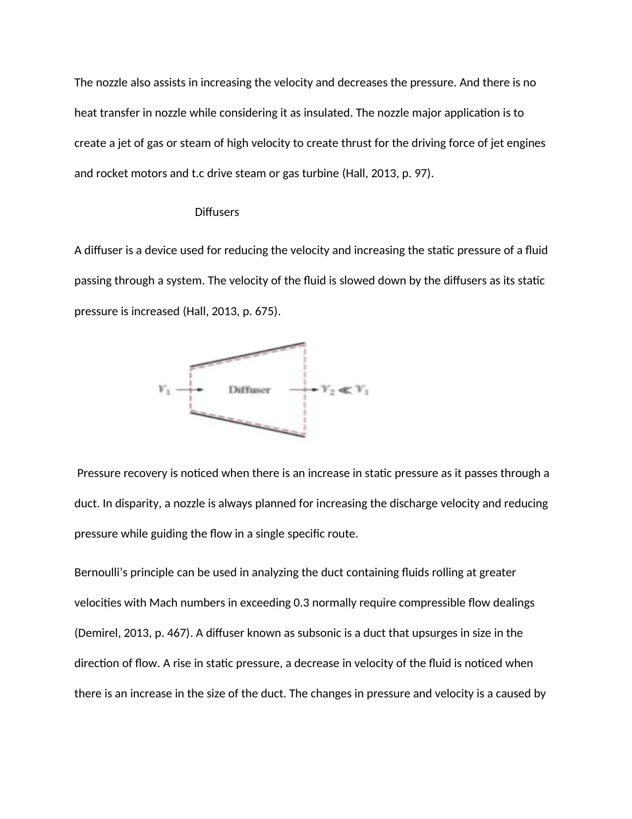
A diffuser is a device used for reducing the velocity and increasing the static pressure of a fluid
passing through a system. The velocity of the fluid is slowed down by the diffusers as its static
pressure is increased (Hall, 2013, p. 675).
Pressure recovery is noticed when there is an increase in static pressure as it passes through a
duct. In disparity, a nozzle is always planned for increasing the discharge velocity and reducing
pressure while guiding the flow in a single specific route.
Bernoulli’s principle can be used in analyzing the duct containing fluids rolling at greater
velocities with Mach numbers in exceeding 0.3 normally require compressible flow dealings
(Demirel, 2013, p. 467). A diffuser known as subsonic is a duct that upsurges in size in the
direction of flow. A rise in static pressure, a decrease in velocity of the fluid is noticed when
there is an increase in the size of the duct. The changes in pressure and velocity is a caused by
Bernoulli’s principle and mass flow rate (Johnson, 2015, p. 142). The Mach number is merely
the ratio of the speed of an object to the speed of sound
The calculation of mass flow rate can be done by
M= p. V = p.v.A
Where
V is the volume flow rate
P is the mass density of the fluid
V is the flow velocity of the mass elements
A is the cross-sectional vector area
Supersonic diffusers are a type of duct whose size declines in the flow route. As the size duct
reduces, there is increment in the fluid density, pressure and temperature of the fluid as the
velocity decreases (Klapp, 2016, p. 318). These changes in temperature, density, velocity, and
pressure are caused by compressible flow. There are certain devices that should not place near
diffusers inlet for example extractors and dampers since they increase noise production and in
case of compiled performance of the diffuser, a duct straight section requires a diffuser.
⊘ This is a preview!⊘
Do you want full access?
Subscribe today to unlock all pages.

Trusted by 1+ million students worldwide
4. Applications
Applications of diffusers
The diffusers are used in;
a) Centrifugal compressors
b) Axial flow compressors
c) Ramming of air in the aircraft
Centrifugal compressors
This type of compressor is also termed as radial compressors are sub-class of dynamic
axisymmetric work-absorbing turbomachinery (Bollinger, p. 45). The pressure is achieved in
idealized dynamic turbomachines through the addition of kinetic energy to uninterrupted fluid
flow by using impeller or rotor. The conversion of kinetic energy into static pressure or
potential energy takes place by slowing the flow via a diffuser. The rise in pressure in diffuser
section and rise in the impeller is equal in most cases (Flack, 2009, p. 32)The run is unchanging,
straightforward and lacks vorticity in a situation where the flow goes via a straightforward pipe
to get into a centrifugal compressor (Sivo, 2012, p. 421).
As the flow endures to pass into and through the centrifugal impeller, the impeller forces the
flow to spin faster and faster. The flow leaving the centrifugal impeller is traveling at speed near
to that of sound (Sethu, 2008, p. 99). The reduction in velocity causes the rise in pressure
resulting in a compressed fluid. The centrifugal has various applications for example in gas;
Paraphrase This Document
Need a fresh take? Get an instant paraphrase of this document with our AI Paraphraser
Centrifugal are used in gas turbine and they are commonly made from titanium alloy forgings.
In the automotive engine, the combination with interchanging internal combustion engines is
done by the centrifugal.
The centrifugal compressors are used in gas moving from the manufacture place to the
consumer in the pipeline of natural gas. The centrifugal compressors are also used in factories
making oil, chemical industries, petrochemical and processing of natural-gas.
The centrifugal compressors are also used in air-conditioning and refrigeration and HVAC to
supply the compression in water chillers cycles. It also used in industries for separating air
needed in manufacturing a refined end product gases (Saha, 2016, p. 128).
Axial flow compressors
An axial flow compressor is a type of compressor that continuously pressurize gases. It allows
the gas or the functioning fluid to flow similar to the rotation axis since it is a rotating airfoil-
based compressor (Peters, 2009, p. 654). The fluid level of energy increases as it flows through
the compressors as a result of the rotor blade action which applies a torque on the fluids. The
fluid is slowed by the stationary blade, changing the circumferential component of flow into
pressure (Bain, 2011, p. 32).
A continuous flow of compressed gas is produced by the axial flow compressors and have
benefits huge mass flow rate and high efficiency though, large pressure rise can be achieved by
the presence of seven rows of airflows. This type of compressor is also used in industrial
applications such as large volume air separation plants, propane dehydrogenation, blast
furnace air and fluid catalyst cracking air. They are also used in aerospace engines because of
flexible operation, high reliability during the flight envelope (Nguyen, 2009, p. 174).
Through diffusion, the immobile airfoils also termed as vanes or stators transform the amplified
revolving kinetic energy into static pressure and then the flow direction of the flow is
redirected. The cross-sectional area between the casing and rotor blades is reduced in the
direction of the flow in order to uphold an optimal Mach number using geometry as the fluid is
compressed (Demirel, 2013, p. 24). During operation, the diffuser action in stator converts
absolute kinetic head in the energy equation. The pressure increase created via a solitary stage
is restricted by the relative velocity between the fluid and the rotor, and the turning and
diffusion capabilities of the airfoils (Ludke, 2008, p. 123).
Ramming of air in aircraft
A ram-air intake uses a dynamic air pressure formed by the motion of the vehicle to increase
the static air pressure inside the intake manifold on an internal combustion engine. Therefore, a
greater mass flow will be permitted through the engine thus increasing the power of the engine
(Ludke, 2008, p. 452).
The ram-air intake operates by instigating the area of the cross-section of the intake ducting
and decreasing the velocity of the intake air. There is an increased in static pressure, reduction
in dynamic pressure as a result of a decrease in the velocity of the gas. The static pressure in
the plenum chamber affects the power of the engine since the density of air is increased thus
leading to higher pressure. Ram air system is used in parachutes for pressurizing a runs of the
⊘ This is a preview!⊘
Do you want full access?
Subscribe today to unlock all pages.

Trusted by 1+ million students worldwide
cell to provide the aerofoil shape such that at subsonic speed, the static pressure increases
while the velocity of air is reduced to zero (Ahn, 2011, p. 320).
Applications of nozzle
Use in aircraft
A thrusting nozzle is a type of nozzle that assist in conversion of gas turbine into a jet engine
(Ludke, 2008, p. 45). The available energy in the exhaust gas turbine is transformed into a great
speed thrusting with a deleterious nozzle which create a great speed thrusting jet from the air
energy that has gone via the fan (Klapp, 2016, p. 76). The gas is accelerated by the propelling
nozzles to supersonic or subsonic velocities based on the engine power setting, internal shape
and pressures at an entry to, and exit from the nozzle (Kraus, 2011, p. 287).
The internal shape may be convergent-divergent (C-D) or convergent. The jet can be
accelerated to supersonic velocities by the C-D nozzles while the jet cannot be accelerated
beyond sonic speed via the convergent nozzle. The nozzles propelling may have a immobile or
flexible geometry to render dissimilar departure zones of regulating the engine action when
furnished with a reheat system or afterburner. Nozzles of the flights moving with supersonic
speed, at which pressure ratios of high nozzles are produced, also have flexible area divergent
sections (Lieberman, 2012, p. 43).
The operation of the nozzle takes place agreeing to the effect of Venturi to allow the drain
gases to ambient pressure and thus create them into a comprehensible jet. The jet may be
supersonic as a result of extreme pressure making the flow to be a choke. A forward thrust on
Paraphrase This Document
Need a fresh take? Get an instant paraphrase of this document with our AI Paraphraser
the airframe is created by air-breathing engines through divulging a remaining rearward thrust
to the air by creating a jet of exhaust gases owning a speed that surpasses that of the aircraft.
The nozzle area is also varied during dry thrust conditions or non-afterburning on few engines
fitted out with an afterburner. At the starting or at idle, the nozzle is opened fully and it may be
closed down in case of advancement of the thrust lever attaining its minimum area before or at
maximum dry thrust setting (Johnson, 2015, p. 87).
A convergent nozzle is applied in several jets engines and it becomes choke when the pressure
ratio exceeds the critical value of around 18.1. And this causes increase in the pressure of the
atmosphere captivating downstream of the throat. The air flowing in a supersonic speed into a
scramjet permits the use of a simple divergent nozzle. The engines capable of supersonic flight
have convergent-divergent exhaust duct features to produce supersonic flow.
Flow measurement
The placing of the flow nozzle in a pipe carrying whose flow rate is to measured, the flow nozzle
leads to a pressure drip which varies with the rate of flow. The measuring of pressure dropping
is carried out using a differential pressure sensor and it come to be a measure of flow rate
when calibrated. The fluid whose rate of flow needs to measured enters the nozzle smoothly to
the throat section having a minimum area.
The pressure of the fluid before entering the nozzle is p1 and as it enters the nozzle, the
pressure of fluid converges keeps on reducing until the minimum cross-sectional area known as
the throat is attained. The minimum pressure p2 at the nozzle throat is retained in the fluid for
a small length after being discharged in the downstream also.
The pressure difference recorded between p1-p2 point 1 and 2 is attached to the differential
pressure sensor. The two points become a sign of the flow rate of the fluid via the pipe when
calibrated.
The flow nozzle is used in measuring liquids flow rate discharged into the atmosphere and also
used in high pressure and temperature steam flows (Klapp, 2016, p. 21).
Gas turbines
The fuel nozzle is used in introducing of the fuel into the chamber of combustion thus creating
an extremely atomized and precisely formed spray of fuel fit for speedy mixing and combustion.
The duplex or simplex nozzle are used by most engines through the simplex engine is not
capable of providing a acceptable spray pattern with the changes in the pressure of fuel but it is
simple to design as the name implies. In duplex nozzle, both the duplex nozzle and fuel flow
divider works hand in hand. The duplex nozzle is capable of providing a better fuel optimization
and proper spray pattern (Lieberman, 2012, p. 196).
Act as ejectors for supplying feed water to boilers
The most necessary portion of boiler actions is the boiler feed water and it is placed into the
drum of steam from the feed pump. The conversion of the feed water into steam from the heat
takes place in the steam drum. The dumping of steam is done in the condenser after usage after
which pumping of the dumbed steam is carried out for the deaerating feed tank. From the tank,
⊘ This is a preview!⊘
Do you want full access?
Subscribe today to unlock all pages.

Trusted by 1+ million students worldwide
1 out of 23
Related Documents
Your All-in-One AI-Powered Toolkit for Academic Success.
+13062052269
info@desklib.com
Available 24*7 on WhatsApp / Email
![[object Object]](/_next/static/media/star-bottom.7253800d.svg)
Unlock your academic potential
Copyright © 2020–2026 A2Z Services. All Rights Reserved. Developed and managed by ZUCOL.


