Number System Conversions and Logic Circuit Design

Verified

Added on  2024/07/01

|9
|1338
|449
AI Summary
This document explores various number system conversions, including hexadecimal to binary, decimal to binary, binary to hexadecimal, and 2's complement representation. It also delves into the design and analysis of logic circuits, including XOR gate construction and a circuit for college session enrollment. The document provides detailed explanations, truth tables, K-maps, and logical equations for each conversion and circuit design.

Contribute Materials

Your contribution can guide someone’s learning journey. Share your documents today.
Document Page
Question 1
A.
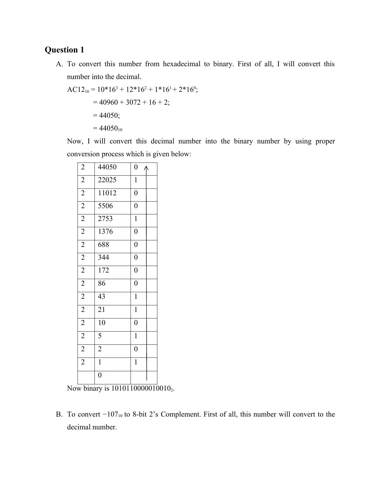
To convert this number from hexadecimal to binary. First of all, I will convert this
number into the decimal.

AC12
16 = 10*163 + 12*162 + 1*161 + 2*160;
= 40960 + 3072 + 16 + 2;

= 44050;

= 44050
10
Now, I will convert this decimal number into the binary number by using proper

conversion process which is given below:

2
44050 0
2
22025 1
2
11012 0
2
5506 0
2
2753 1
2
1376 0
2
688 0
2
344 0
2
172 0
2
86 0
2
43 1
2
21 1
2
10 0
2
5 1
2
2 0
2
1 1
0

Now binary is 1010110000010010
2.
B.
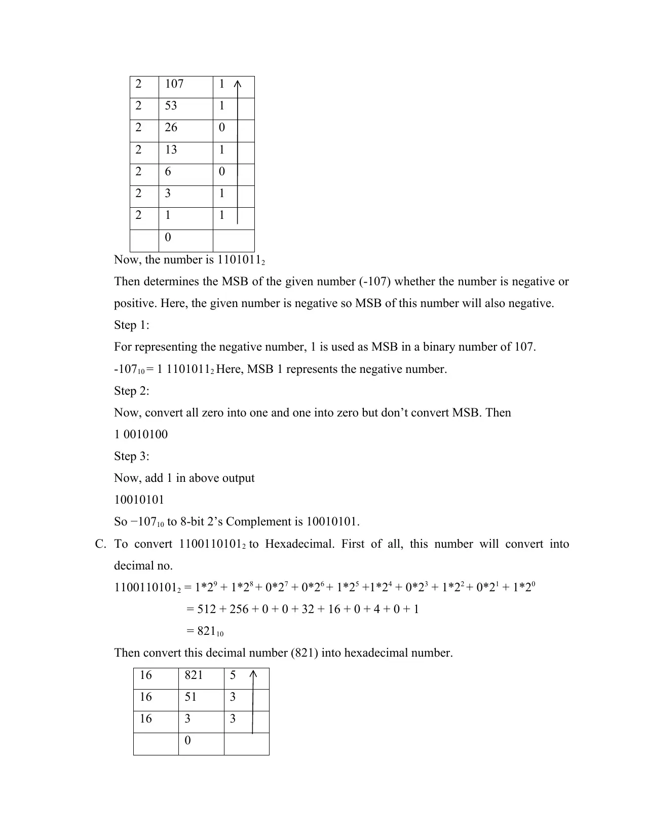
To convert −10710 to 8-bit 2’s Complement. First of all, this number will convert to the
decimal number.

Secure Best Marks with AI Grader

Need help grading? Try our AI Grader for instant feedback on your assignments.
Document Page
2 107 1
2
53 1
2
26 0
2
13 1
2
6 0
2
3 1
2
1 1
0

Now, the number is 1101011
2
Then determines the MSB of the given number (-107) whether the number is negative or

positive. Here, the given number is negative so MSB of this number will also negative.

Step 1:

For representing the negative number, 1 is used as MSB in a binary number of 107.

-107
10 = 1 11010112 Here, MSB 1 represents the negative number.
Step 2:

Now, convert all zero into one and one into zero but don’t convert MSB. Then

1 0010100

Step 3:

Now, add 1 in above output

10010101

So −107
10 to 8-bit 2’s Complement is 10010101.
C.
To convert 11001101012 to Hexadecimal. First of all, this number will convert into
decimal no.

1100110101
2 = 1*29 + 1*28 + 0*27 + 0*26 + 1*25 +1*24 + 0*23 + 1*22 + 0*21 + 1*20
= 512 + 256 + 0 + 0 + 32 + 16 + 0 + 4 + 0 + 1

= 821
10
Then convert this decimal number (821) into hexadecimal number.

16
821 5
16
51 3
16
3 3
0
Document Page
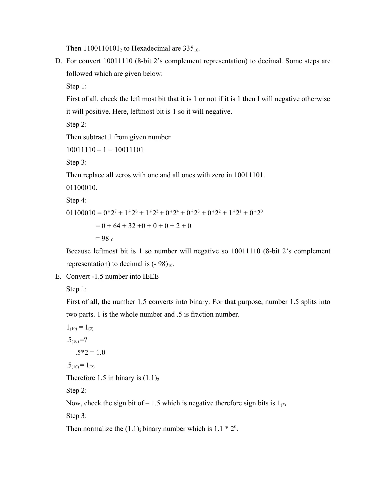
Then 11001101012 to Hexadecimal are 33516.
D.
For convert 10011110 (8-bit 2’s complement representation) to decimal. Some steps are
followed which are given below:

Step 1:

First of all, check the left most bit that it is 1 or not if it is 1 then I will negative otherwise

it will positive. Here, leftmost bit is 1 so it will negative.

Step 2:

Then subtract 1 from given number

10011110 – 1 = 10011101

Step 3:

Then replace all zeros with one and all ones with zero in 10011101.

01100010.

Step 4:

01100010 = 0*2
7 + 1*26 + 1*25 + 0*24 + 0*23 + 0*22 + 1*21 + 0*20
= 0 + 64 + 32 +0 + 0 + 0 + 2 + 0

= 98
10
Because leftmost bit is 1 so number will negative so 10011110 (8-bit 2’s complement

representation) to decimal is (- 98)
10.
E.
Convert -1.5 number into IEEE
Step 1:

First of all, the number 1.5 converts into binary. For that purpose, number 1.5 splits into

two parts. 1 is the whole number and .5 is fraction number.

1
(10) = 1(2)
.5
(10) =?
.5*2 = 1.0

.5
(10) = 1(2)
Therefore 1.5 in binary is (1.1)
2
Step 2:

Now, check the sign bit of – 1.5 which is negative therefore sign bits is 1
(2).
Step 3:

Then normalize the (1.1)
2 binary number which is 1.1 * 20.
Document Page
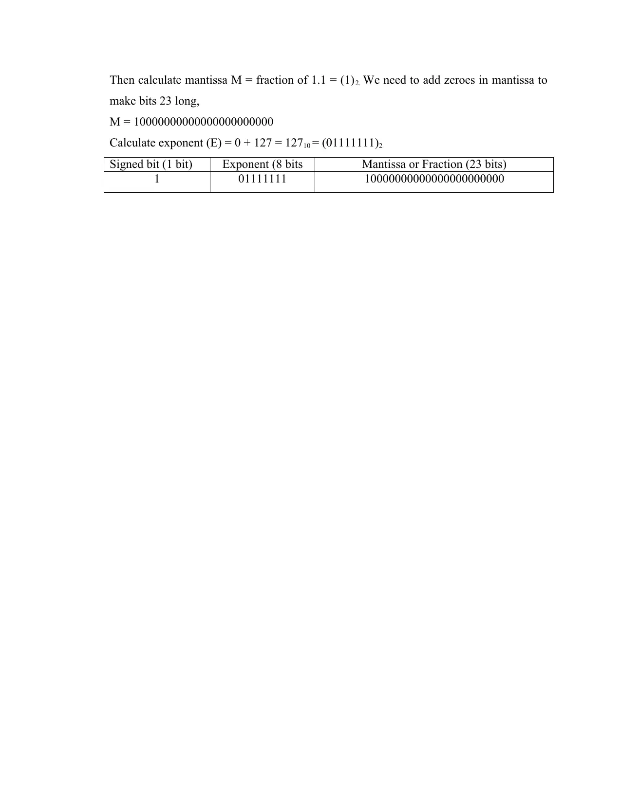
Then calculate mantissa M = fraction of 1.1 = (1)2. We need to add zeroes in mantissa to
make bits 23 long,

M = 10000000000000000000000

Calculate exponent (E) = 0 + 127 = 127
10 = (01111111)2
Signed bit (1 bit)
Exponent (8 bits Mantissa or Fraction (23 bits)
1
01111111 10000000000000000000000

Secure Best Marks with AI Grader

Need help grading? Try our AI Grader for instant feedback on your assignments.
Document Page
Question 2:
A.
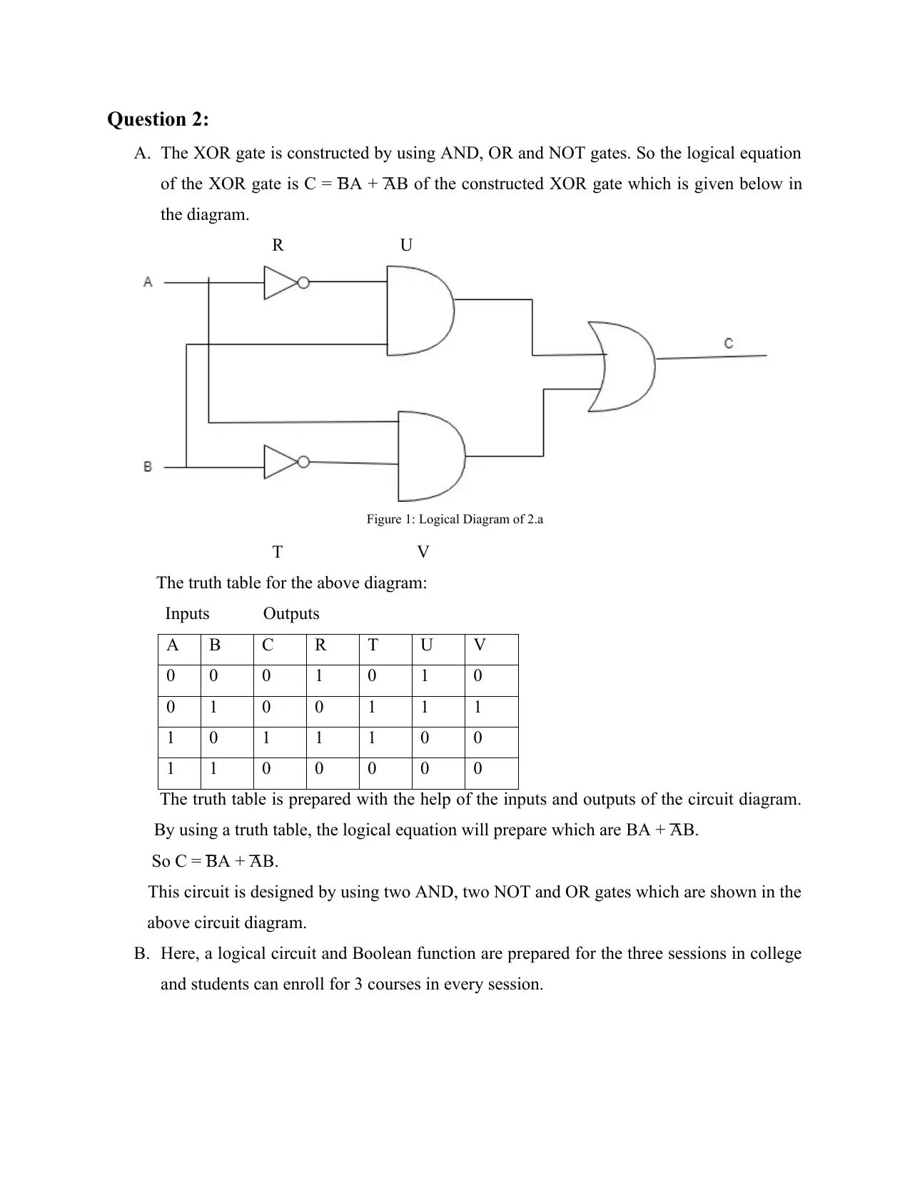
The XOR gate is constructed by using AND, OR and NOT gates. So the logical equation
of the XOR gate is C =
͞ BA + ͞ AB of the constructed XOR gate which is given below in
the diagram.

R U

Figure
1: Logical Diagram of 2.a
T V

The truth table for the above diagram:

Inputs Outputs

A
B C R T U V
0
0 0 1 0 1 0
0
1 0 0 1 1 1
1
0 1 1 1 0 0
1
1 0 0 0 0 0
The truth table is prepared with the help of the inputs and outputs of the circuit diagram.

By using a truth table, the logical equation will prepare which are
BA + ͞ AB.
So
C = ͞ BA + ͞ AB.
This circuit is designed by using two AND, two NOT and OR gates which are shown in the

above circuit diagram.

B.
Here, a logical circuit and Boolean function are prepared for the three sessions in college
and students can enroll for 3 courses in every session.
Document Page
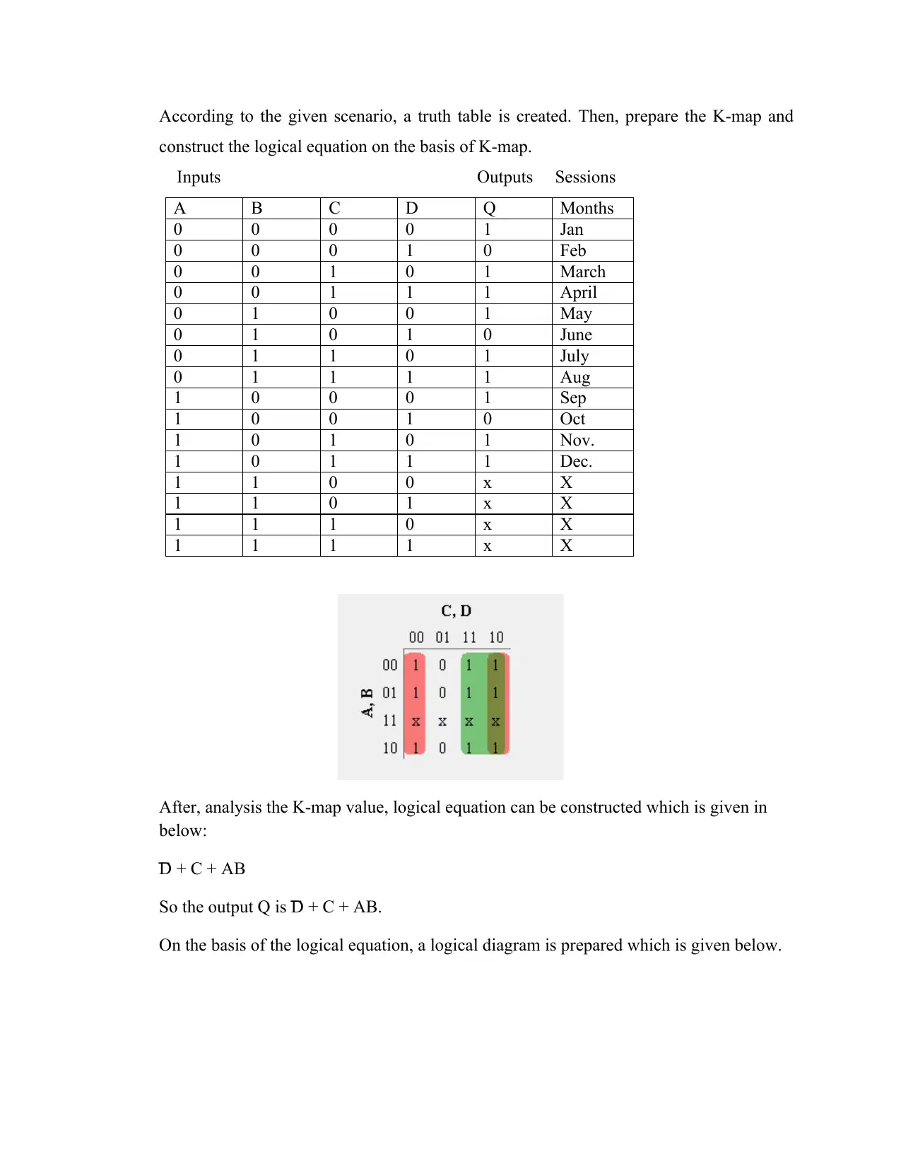
According to the given scenario, a truth table is created. Then, prepare the K-map and
construct the logical equation on the basis of K-map.

Inputs Outputs Sessions

A
B C D Q Months
0
0 0 0 1 Jan
0
0 0 1 0 Feb
0
0 1 0 1 March
0
0 1 1 1 April
0
1 0 0 1 May
0
1 0 1 0 June
0
1 1 0 1 July
0
1 1 1 1 Aug
1
0 0 0 1 Sep
1
0 0 1 0 Oct
1
0 1 0 1 Nov.
1
0 1 1 1 Dec.
1
1 0 0 x X
1
1 0 1 x X
1
1 1 0 x X
1
1 1 1 x X
After, analysis the K-map value, logical equation can be constructed which is given in

below:
͞
D + C + AB

So the output Q is ͞
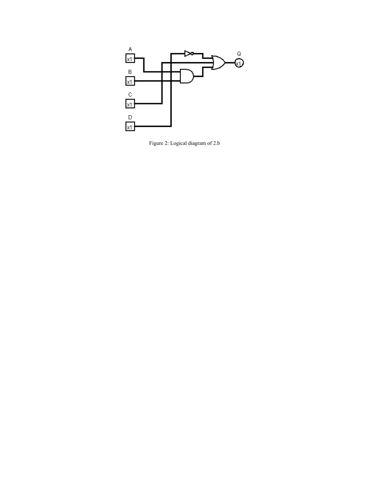
D + C + AB.
On the basis of the logical equation, a logical diagram is prepared which is given below.
Document Page
Figure 2: Logical diagram of 2.b

Paraphrase This Document

Need a fresh take? Get an instant paraphrase of this document with our AI Paraphraser
Document Page
Question 3:
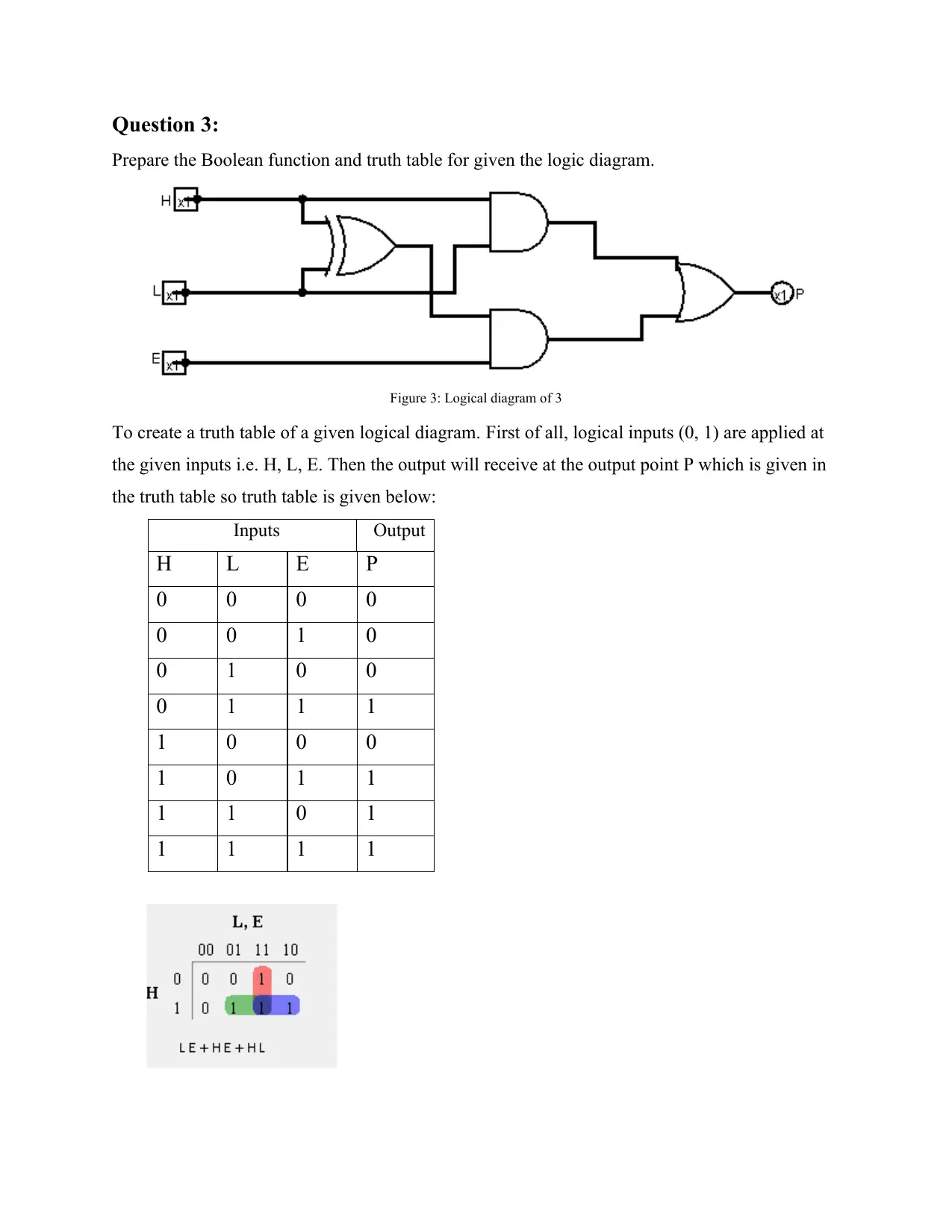
Prepare the Boolean function and truth table for given the logic diagram.

Figure
3: Logical diagram of 3
To create a truth table of a given logical diagram.
First of all, logical inputs (0, 1) are applied at
the given inputs i.e. H, L, E. Then the output will receive at the output point P which is given in

the truth table so truth table is given below:

Inputs
Output
H
L E P
0
0 0 0
0
0 1 0
0
1 0 0
0
1 1 1
1
0 0 0
1
0 1 1
1
1 0 1
1
1 1 1
Document Page
After, construct the truth table of given design, K-map is created by using this truth table. After
that, analysis the K-map, the final logical equation is obtained for the given logical diagram

which is given below:

Logical Equation is LE + HE + HL
1 out of 9
circle_padding
hide_on_mobile
zoom_out_icon
[object Object]

Your All-in-One AI-Powered Toolkit for Academic Success.

Available 24*7 on WhatsApp / Email

[object Object]