Numerical Modeling and Simulation of Euler-Euler Multiphase Flow
VerifiedAdded on 2023/05/28
|38
|9711
|473
AI Summary
This report presents a thorough analysis of numerical modeling and simulation of Euler-Euler multiphase flow and compares it with alternative liquid models. The methodology, results, and discussion are included in the report. The subject is engineering and the course code, course name, college/university are not mentioned.
Contribute Materials
Your contribution can guide someone’s learning journey. Share your
documents today.
PROJECT REPORT CAREER EPISODES2
[Author Name(s), First M. Last, Omit Titles and Degrees]
[Institutional Affiliation(s)]
[Author Name(s), First M. Last, Omit Titles and Degrees]
[Institutional Affiliation(s)]
Secure Best Marks with AI Grader
Need help grading? Try our AI Grader for instant feedback on your assignments.
ABSTRACT
The paper presents a thorough report on the numerical of Euler-Euler multiphase flow modeling
and simulation project. Moreover, a similar report was additionally carried out against elective
quantity of liquid model dependent on the stage field strategy that was observed to be more
favorable in key angles, for example, the nonattendance of unphysical interfacial pressure
motions and the capacity to represent variations in the surface pressure power. Also these lines
foresee a few air pocket lengths under constant flow conditions while checking the material
science of homogeneous two-phase phase. Various air pocket experiments instruments were
simulated and analyzed against test discoveries in the literature. The simulation of a thin fluid
film at the tube wall was observed to be a confinement of generally works relating to Euler flow,
including the present(Simon, Foley, K. T., Carls, & Melkent 2005).
This was credited to be almost certain because of constrained dimensional and spatial goals as
well as erroneous contact point with elements instead of restrictions of the demonstrating
approach itself. The impact of wall bond was contemplated with regard to the flow and pressure
field in the tube. An approval of the model was accomplished through a great examination of the
numerically anticipated gas void portion and air pocket lengths with existing models and
connections. All in all, the phase field technique was finished up to have enhanced prescient
precision as for certain viewpoints when contrasted with traditional multiphase flow models.
INTRODUCTION
Micro scale techniques are rapidly infiltrating in new application territories because of their
demonstrated potential for process upgrade as well as gear estimate/volume decrease in various
building applications. At the point when ideally planned ,the intrinsic higher surface zone to
volume ratio of smaller scale frameworks gives considerable heat exchange upgrade while
keeping pressure drops at moderate dimensions. Two-phase flow in micro channels has been a
subject of heightened enthusiasm for the past couple of decades. Micro channel phase change
takes place where heat and mass exchangers are specifically required in applications which are
industrial in nature. The heat/mass exchange coefficients as high as 1,000,000 W/m2K are
expected to fulfill a portion of the high-transition cooling requirements of certain elite, complex
system. The flow highlights at the micro scale vary essentially from that of macro scale flow. On
the test front, there exists an immense sum of distributed works, beginning from the early
investigations of researchers for macro scale flow and that of scholars for flow at littler scales up
to works done in later occasions fundamentally concentrating on micro scale streams. Some
scholars as of late shared a far reaching audit of the test works relating to gas-fluid two-stage
streams in micro channels. They grouped the observed flow system into the surface pressure
ruled sort, including Euler also, turbulent flow; the transitional sort, including stir and Euler
flows; and the inactivity ruled sort, including diffused as well as and streamlined flow . In the
considered flow designs, Euler stream described by an exchanging fluid of small and gas
particles design was actually the prevailing examination intrigue, particularly for micro scale
high temperature and weight exchangers. It was as a result within recycling speed segments in
either phase which improves convective blending. At present, a few spreading models that were
present for mathematical generation of two-stage stream within micro channels, for example, the
dispersed power display and the continuum surface power (CSF) display among others. The last
has been generally connected to use of the volume of flow (VOF) as well as similar dimension
group strategies. The phase field strategy has a place with the class of diffuse interface methods.
Be that as it may, dissimilar to the CSF alongside disseminated power models, which depend on
surface strain powers, a stage section technique as in view of available power. The two stage
are regarded as blend within the superficial region as well as correlation along these lines there is
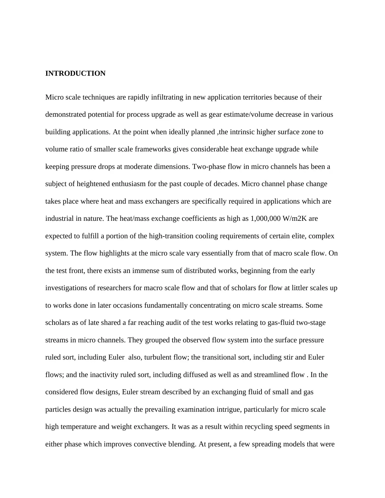
connection with a blending energy as given by Eq. 1.
…………………………….1
The lambda is a scalar variable alluded to as the phase field variable as described by scholars and
is considered as a ratio of phase. It takes two particular qualities in either phase and experiences
a fast smooth change in the interfacial region. This blending energy adds to the aggregate free
energy thickness of the framework, ftot (J/m3 ). Here, t is the blending energy thickness having
measurements of power (N) and f scales with the thickness of the interface (m). The sharp
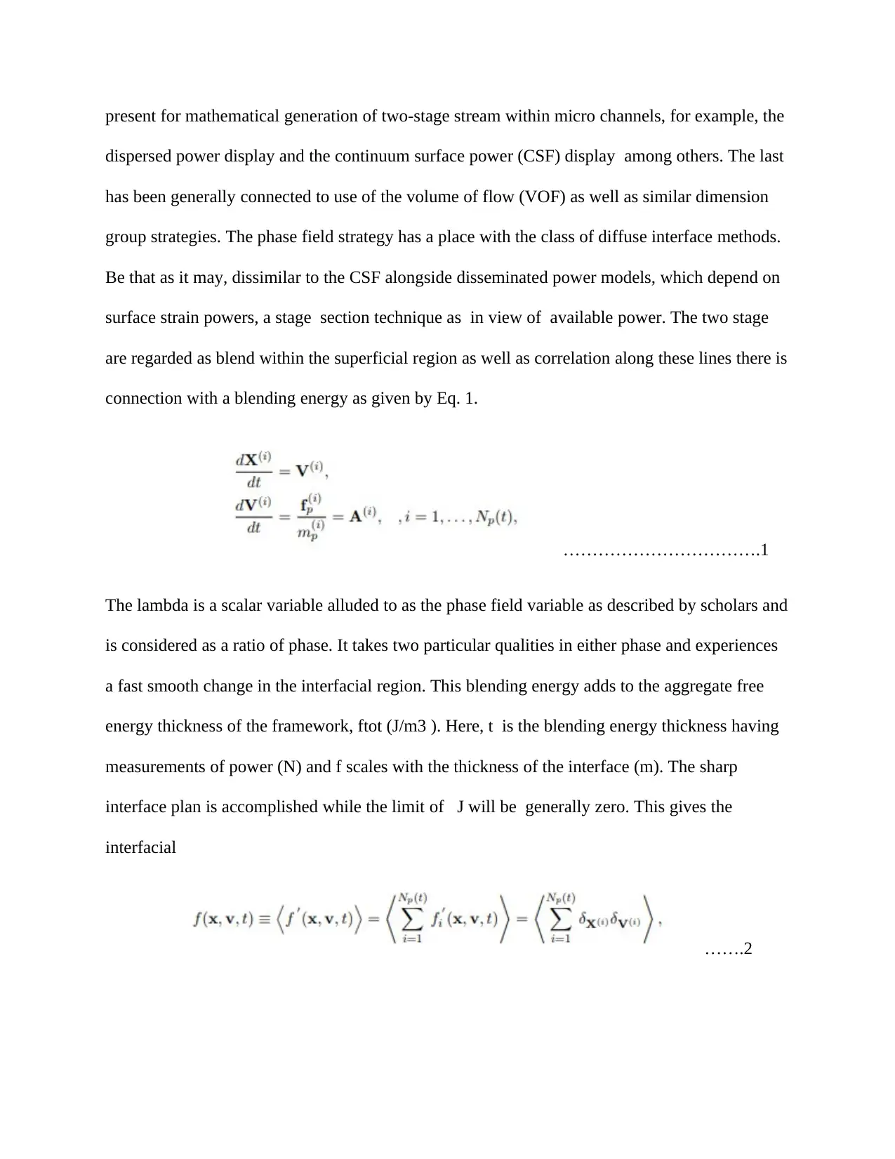
interface plan is accomplished while the limit of J will be generally zero. This gives the
interfacial
…….2
Secure Best Marks with AI Grader
Need help grading? Try our AI Grader for instant feedback on your assignments.
As illustrated by scholars, the reliance of experimental precision on three client characterized
parameters: the interface width, the portability, and the component estimate, h, represented extra
stresses on record of the nonappearance of governance equations on their choice. It is noticed
that the component estimate, h, is considered here since the dimension of area goals that is
required is reliant on the client characterized thickness of the interface. To conquer these issues,
an equation, h ≤ lambda sign was proposed by, where h and lambda symbol are the component
estimate and interface thickness parameter separately. Further, the h value was shifted from 0.5
to 1 so as to guarantee that the area involved by the interface would be adequately settled with
something like 7-10 components as recently prescribed in the project. To this point, it is noticed
that the above model and the related h/ lambda ratio esteems are not all inclusive in nature since
the interface thickness parameter term is just a relative and not supreme ratio of the real
thickness of the interface(Roldán & Gámiz 2004). During the project, there was connection in
the phase field technique to simulate two-phase flow in a smaller scale tube concentrating on
bubbly and Euler equations. In a further investigation, there was thought about the continuum
surface force (CSF) and the stage field techniques for representing the surface pressure constrain
in two-phase phase models. The two models were connected to 2-D simulation of air-water two-
phase flow in a miniaturized scale container of 600 μm distance across for the Euler and bubbly
flow equations. It was seen that the flow field anticipated by the CSF strategy was described by
expanded courses coming about because of unphysical, parasitic speed parts. Be that as it may,
this was appeared to be diminished to the dimension of machine precision by utilizing the phase
field experiment by virtue of the proper exchange of the first produced energy due to the
discretization error between the active energy and the surface pressure energy, which is in this
manner expressed as thickness(Patzold 2001). Generally few examinations in project have
connected the phase field model to think about micro scale two-phase model and among these,
scarcely any have executed a similar utilizing exercise with CFD codes. The previous point is
accepted to be a significant inadequacy given the favorable circumstances of stage field
displaying over ordinary methodologies as recorded in project report Likewise, from a simply
specialized perspective, it is very clear that business CFD codes which highlight simple model
execution alongside the alternative to change the inspection conditions according to necessity has
undoubtedly led to an ascent in their popularity for CFD applications on the loose. Explicit to
multiphase flow, this is particularly demonstrated in the solid predominance of models, for
example, the VOF and level-set in different CFD results conformed to Euler flow in micro
channels. Issues with respect to the decision of the phase field parameters have been
contemplated and examined finally. Also, certain themes of momentum look into enthusiasm for
Euler flow demonstrating that so far remain to a great extent uncertain have too been
contemplated utilizing the present model and at times considered at, ceteris paribus, with an
option VOF show.
BACKGROUND
Multiphase flow discovers their application in numerous modern stages. The most regularly
utilized system for multiphase flow is Riser reactors, Bubble section reactors Fluidized bed
reactors Scrubbers, Dryers, and so forth. A phase is characterized as a class of issue which has a
characteristic limit and an explicit unique reaction to the encompassing flow or potential field.
Stages are commonly recognized by solid, liquids or vaporous conditions of issue yet can
likewise allude to different structures e.g. particles of various size. A similar state matters with
various chemical properties are likewise called as states of matter. The fundamental motivation
behind multiphase displaying and simulation is to amplify the contact between the distinctive
stages and for boosting the uses of exchange of mass and the exchange of heat. This undertaking
concentrated on a solitary gas bubble ascending in water, in spite of the fact that similar
strategies were connected to different gas/fluid or fluid/fluid frameworks. Contingent upon air
pocket distance across, this may prompt convoluted two-phase flow. The VOF is a typical
current methodology that is reasonable for precise calculation of the liquid flow within the
ceaseless and dispersed phase, particularly if the interface indicates complex dynamical conduct.
AIM
The main aim of the project was to illustrate the multiphase flow modelling and simulation.
METHODOLOGY
MODEL OF NUMERICAL
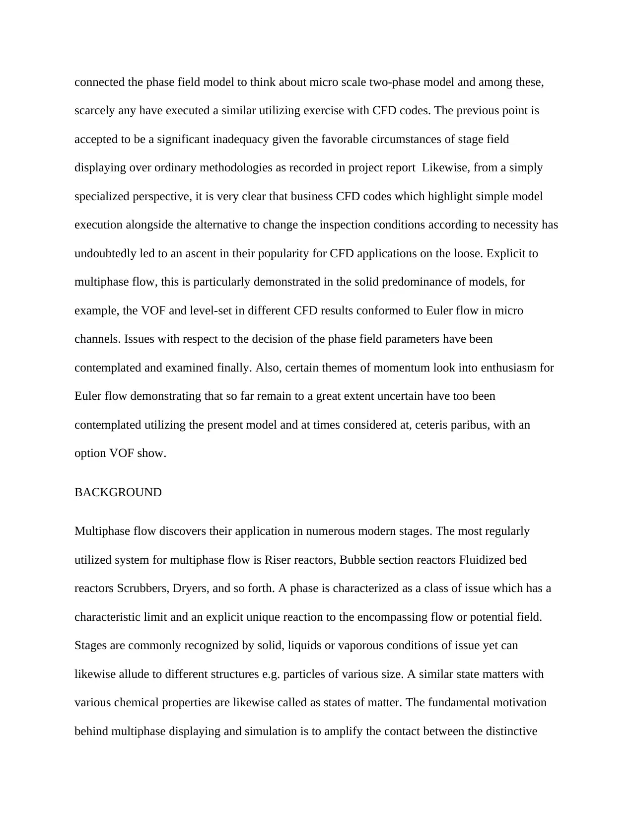
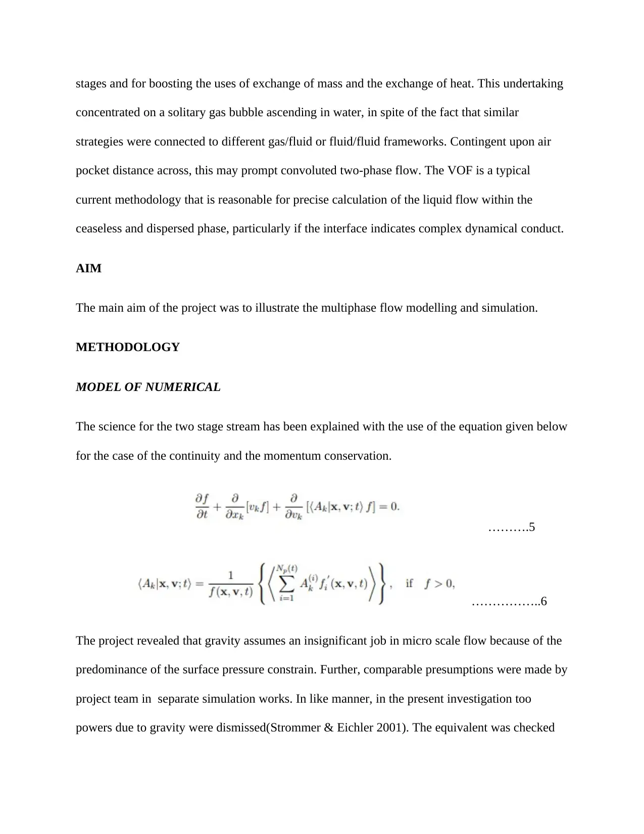
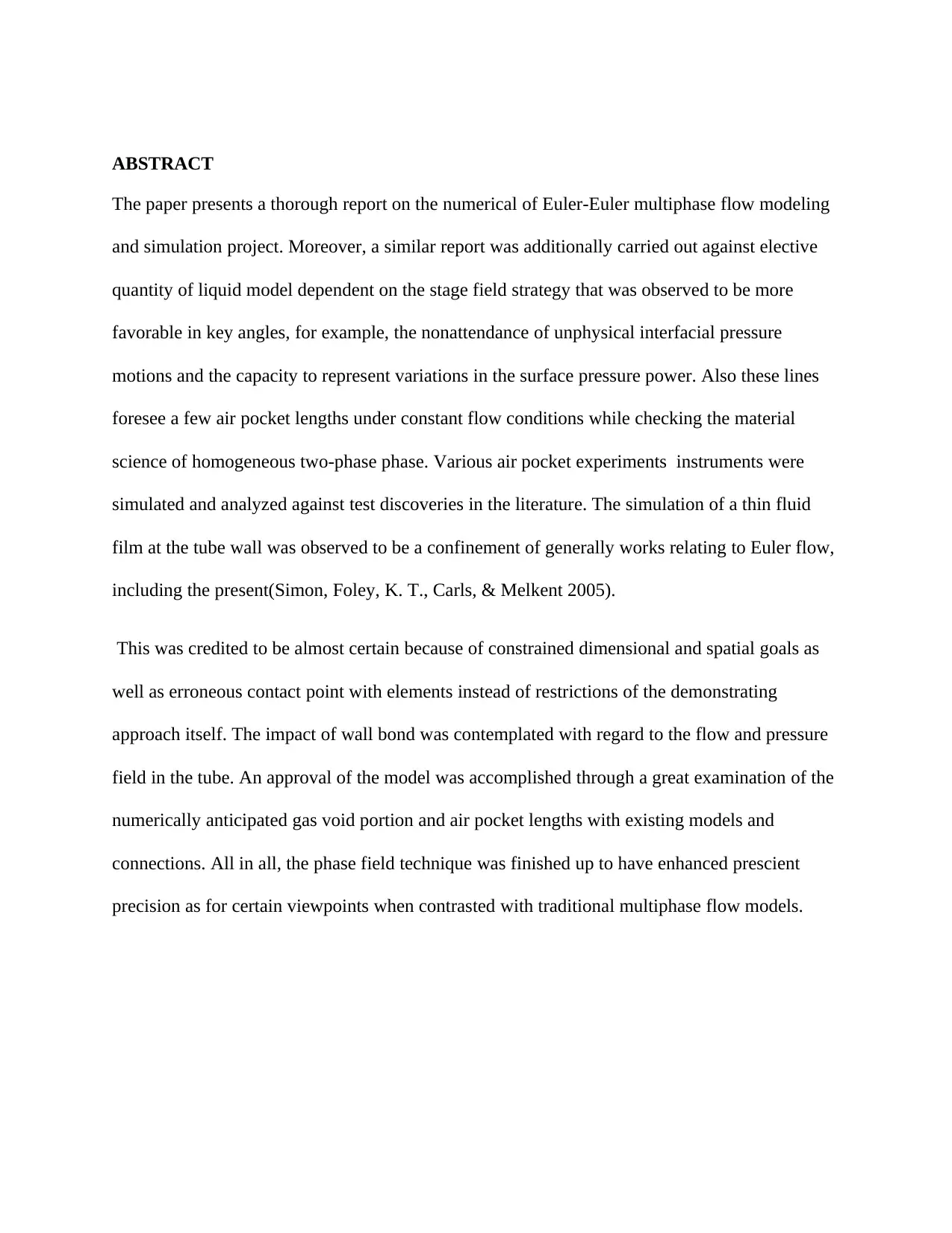
The science for the two stage stream has been explained with the use of the equation given below
for the case of the continuity and the momentum conservation.
……….5
……………..6
The project revealed that gravity assumes an insignificant job in micro scale flow because of the
predominance of the surface pressure constrain. Further, comparable presumptions were made by
project team in separate simulation works. In like manner, in the present investigation too
powers due to gravity were dismissed(Strommer & Eichler 2001). The equivalent was checked
Paraphrase This Document
Need a fresh take? Get an instant paraphrase of this document with our AI Paraphraser
through evaluating more trademark generations, in the presence or absence of the gravity, though
this was considered substantial. Furthermore none connected object power as well as wellsprings
of loose power were put under the consideration. The surface strain was demonstrated as a body
constrain (FST) in the force condition. The interface following was finished by the phase field
strategy utilizing the plan as given by Eqs. 2 and 3. The stage field variable p was utilized to
administer the interface. As a tradition, in the present investigation it was risen to - 1 in the
unadulterated gas phase and +1 in unadulterated fluid phase. A scaling connection, Eq. (6), was
utilized to get the volume portion of either phase, which takes esteems from 0 to 1. The viable
liquid properties like thickness and consistency were figured as the normal estimation of the two
phase pressure by their separate volume portions acquired from Eq. 7
…………..7
Appropriate qualities for the portability and interface thickness parameters q and t were acquired
at an appropriate time size of dispersion that did not unnecessarily soggy the convective
movement but then held a steady interfacial thickness. In like manner, adequate dissemination
was to be available to oppose stressing flows that can thin or thicken the interface. So as to
acquire a physically practical arrangement, the parameter was kept up steady all through the
space. The impact of surface strain was displayed as a body constrains, FST, in the energy
condition. It was figured as the result of the synthetic capability of the framework, G, and the
bias of the phase field variable.
………………8
…………………9
COMPUTATIONAL DOMAIN
This was demonstrated in 2D with a cross flow channel setup as illustrated in Fig 1. The whole
space was discretized with a homogeneous unstructured matrix comprising of triangular
components. To keep up consistent goals of the gas-fluid interface all through the channel, the
whole space was discretized utilizing the comparable measured components. In this manner it
was impractical to utilize a square organized framework with refined work goals close to the
channel walls..
Figure 1: Flow channel (Robinson 2008)
The channels were displayed with a consistent speed limit condition with a solitary phase being
conceded through every channel. A pressure based outpouring limit condition was indicated at
the outlet of the micro channel which indicated a Dirichlet condition on the pressure alongside a
vanishing gooey pressure(Robinson 2008). For the channel walls, no-slip, free-slip or wetted-
wall conditions were material and a close investigation was embraced between them. The last
was executed by determining a static contact point in Eq. (10), in which the right-hand-side
equation is generally displayed as zero for the free-slip/no-slip cases.
An understood time-project calculation was utilized to get the numerical calculations. The phase
field factors were introduced by specifically tackling the two parameters. This transient
introduction was utilized to make the interface. Since the channel was at first thought to be
loaded up with quiet vaporous phase, the underlying interface was framed at the fluid delta. It
was guaranteed for each simulation that the interface made by the introduction method was
monotonic and was dependably within the permitted scope of - 1 to +1. The last transient
simulation was tackled for all the administering conditions utilizing the underlying qualities
shown above. The resistance criteria for the residuals were set to a request size lower than the
solver's default esteems. All simulations were completed on a Dell Precision T5500 workstation
containing two Intel Xeon processors with eight centers, 4 GB of RAM and a Windows 7 32-bit
operating system..
RESULTS AND DISCUSSION
Grid independence
The affectability of the answer for the area discretization (spatial work component type and size)
was considered by checking the gas void division and the air pocket/slug lengths. So as to keep
up steady goals of the interface all through, the estimation of the interface thickness parameter,
was to be close to the component measure, h, in the position possessed by the interface.
Secure Best Marks with AI Grader
Need help grading? Try our AI Grader for instant feedback on your assignments.
Additionally the project team suggested at minimum 7-10 framework components to be available
in the interfacial region to get adequate goals. Since the client characterized estimation of values
in this examination fills in as a general proportion of the interface thickness just and not as an
outright measure.
The range for the h/lambda ratio (between 0.5 to 1) proposed by the project team couldn't be
specifically used in this investigation. Subsequently h/k values going from solidarity until the
point that two were explored as two extraordinary cases. The position inside 0.996 volume part
of vaporous phase (0.004 volume part of fluid stage) was considered to be characterized as the
'interfacial area' for this investigation. For a h/p ratio of unity, it was settled by in excess of 15
components while for a ratio estimation of 2, it was just shy of 10 components. Both these cases
exist in the other literature works. Be that as it may, as found in Fig. 2, better network
independency was obtained with an estimation of solidness for the h/k ratio when contrasted with
an estimation of 2, and consequently the previous one was determined for every further
simulations. The project reports that quadrilateral cells perform better as contrasted with
triangular components as for limiting errors(Picard, DiGioia, Moody & Jaramaz 2003).
These discoveries have been founded on interface following utilization of finite volume usage of
the VOF technique . Subsequently, a similar affectability was assessed for the present finite
element usage of the phase field technique. The current displaying results were observed to be
totally obtuse of the component type. However, the triangular components brought about a
decrease in computational time by almost 20% when contrasted with the quadrilateral
components and thus it was the favored decision in this investigation. This little contrast in
computational time could be ascribed to the reality that the greatest component skewness for the
quadrilateral cells was somewhat higher (0.13) than that for the triangular cells (0.08). The low
estimations of skewness represented here are by virtue of using about comparable measured
components so as to keep up consistent goals of the interface all through the computational
space.
Figure 2: size/length relationship (Robinson 2008)
The impact of versatility (characterized by Eq. 4) on the anticipated flow qualities was
researched. A few simulations were performed by successively expanding the versatility over a
scope of a few requests of greatness.
This was practiced in two phases: first by changing just the versatility parameter, χ, and keeping
the interface thickness parameter, ξ, constant and hence by rehashing the most of the above
mentioned by dividing the interface thickness parameter. In view of this, the range of versatility
researched was 10-8 < γ < 10-4 for various phase shallow speeds going from 0.1 m/s to 1 m/s.
From the huge informational index in this way acquired, the following perceptions were made.
At amazingly low estimations of portability (regularly 10-8 or on the other hand lower), the
experiment did not meet the requirements and along these lines the solver did not finish the
transient simulation run(Lang, Steines, Timsari & Tsougarakis 2008).
As the versatility was expanded, stratified flow was obtained which was delegated an unphysical
set up, given that the normal equation is Euler flow. At higher estimations of change, the flow
progressed into Euler flow in unmistakable phases. At first, a Euler-bubbly change flow was
acquired, trailed by Euler flow with air pocket arrangement by the 'breaking-slug' system
(additionally alluded to as the trickling system; talked about later), and eventually Euler flow
with air pocket arrangement by the crushing component (examined afterward). The above
outcomes are translated as pursues. Low estimations of mobility result in thin-interfacial
stressing flow which need convective movement(Swanson 2006) .
Thus, this is accepted to have made numerical troubles which averted intermingling of the
answer for these cases. Amid the advancement of stratified flow at higher estimations of mobility
i.e. amid the underlying phases of the transient run, the fluid phase flow that advanced through
the channel length was portrayed by an unmistakable nose at the main edge. Be that as it may,
this did not develop into Euler flow. At higher qualities of mobility, the frontal nose necked into
the vaporous phase and totally hindered the gas flow. This rehashing procedure brought about
the age of Euler flow. It is conjectured that since the flow conditions are steady for the two cases,
this change could be ascribed to the anticipated surface pressure drive field. The proportionality
between the surface strains force and the portability can't be comprehended from its definition
given by Eq. 4. Thus, in request to check this speculation, plots of the net surface strain constrain
vectors superimposed on the shapes of the gas void portion were obtained and are introduced in
Fig. 3
Paraphrase This Document
Need a fresh take? Get an instant paraphrase of this document with our AI Paraphraser
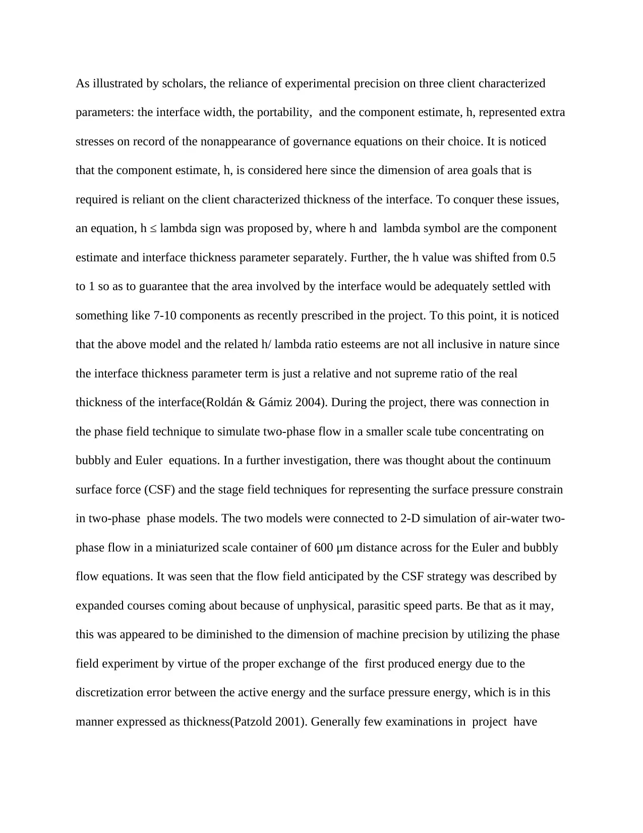
FIG. 3: Predicated numerical surface tension force vectors(Swanson 2006)
Portability among the four cases. Figs. 3 compare to Euler flow simulated with expanding
estimations of portability prompting progressively higher air pocket lengths for each situation.
These outcomes were obtained at one step relating to the fulfillment of Euler bubble separation
from the channel flow.
The cases in Figs. 3a and 3b allude to the change from stratified flow to Euler flow in which, the
powers at the frontal nose of the fluid string act in an upstream bearing, into the fluid phase. This
perception is in concordance with the hypothesis proposed by the project team relating to
interfacial anxieties. Be that as it may, for the stratified flow (Fig. 3a), which happened at lower
portability, the net surface pressure drive vectors upstream of the frontal nose were practically
identical in greatness and were inverse in heading on either side of the interface. This reasonable
arrangement of powers is accepted to have kept air pocket separation from happening and in this
manner bringing about a stratified flow. In actuality, for Euler flow appeared in Fig. 3b, the
forces supposedly was situated towards the upper channel wall but which could have caused the
fluid string to neck in to the vaporous stage and totally square the channel prompting consequent
air pocket separation(Figueiredo, Jesus, Machado, Ferreira & De Carvalho 2001).
The above examination unmistakably confirms that the anticipated surface pressure force field is
a capacity of the characterized mobility. In synopsis, an unphysical, exceedingly low estimation
of portability results in an over-forecast of the 'settling impact' of the surface strain forces while
with adequate characterized mobility, the forces are organized reasonably for Euler bubble
development. At further higher estimations of portability, the Euler bubble length increases.
This, as appeared in Figs. 3b, 3c and 3d, is in concurrence with the above perceptions since the
surface pressure constrain field which is somewhat adjusted in Fig. 3b, apparently was
progressively uneven for the rest of the cases, with the nearness of overwhelming forces acting in
just a single bearing, i.e. into the fluid phase an upstream way.
This is accepted to have made a contradicting impact keeping the fluid phase from necking into
the vaporous phase and in this manner coming about in expanding measures of the vaporous
flow entering the channel and adding to the development of a more drawn out Euler bubble. A
fascinating perception was that even with expanding Taylor bubble lengths, the gas void division
remained about steady. This perception, appeared for a trademark case in Fig. 4, shows the
assertion between the present multiphase flow display with homogeneous two-phase flow and
features that for a consistent flow condition, the gas void division is probably not going to be
changed, despite the fact that the air pocket lengths may fluctuate due to surface strain impacts.
This being an aftereffect of the nearness of the mobility, h, in the administering conditions is
closed as a noteworthy favorable position of the phase field strategy over traditional
methodologies for displaying of multiphase two-phase flow which yield just a solitary bubble
length for some random flow condition.
FIG. 4: Variation of the gas void and the bubble length(Figueiredo, Jesus, Machado, Ferreira &
De Carvalho 2001)
It merits reminding at this point the surface pressure powers work notwithstanding the weight
drop, shear pressure and other components in charge of Euler bubble development. Its relative
size between different cases just serves to alter the subsequent qualities of the Euler flow like air
pocket/slug length.
In all the above simulation, the interface thickness parameter was kept up a constant, while the
portability parameter was fluctuated to impact a net change in the mobility. So as to think about
the separated impact of the interface thickness parameter, a series arrangement of simulations
were performed with the all the past estimations of portability parameter and a lower, consistent
estimation of interface thickness parameter, ξ. As an experiment, the interface thickness
parameter was split from its past esteem and somewhat unique characteristics were observed. At
the most reduced portability, non-joining arrangements were more normal, which is sensible
given that these cases are profoundly implausible. The stratified stream was described by a wavy
interface that swayed all through the transient simulation, when contrasted with the static
interface acquired in the past cases. Fig. 5 shows these interfacial motions for a trademark case,
Secure Best Marks with AI Grader
Need help grading? Try our AI Grader for instant feedback on your assignments.
contrasted and the uniform interface acquired with the higher estimation of ξ. Aside from this, no
major contrasts were observed.
FIG. 5: Variation of time and interface position for ξ = 25, 50 μm(Booker & Dunbar 2004)
Wall Adhesion
A few flow highlights of Euler flow could be impacted by the condition at the channel wall. The
failure to catch the fluid film at the channel wall by numerical simulations has frequently been
credited as an almost certain reason for a few anticipated stream highlights. Furthermore,
displaying of wall grip when contrasted with no-slip and free-slip flow additionally requires
examination.
Global Flow Features
Euler flow in micro channels was explored with three kinds of limit conditions: no-slip, free-slip
and wetted wall.. All the three kinds were explored for a 500 μm channel with cross flow gulf
setup having gas and fluid phase shallow speeds of 0.1 m/s. The mobility was kept up steady in
all cases. The entire phase dispersion was observed to be comparative for all the simulated
cases, i.e. aside from the distinctions in the air pocket top profiles due to indicating a static
contact edge (90° or something else). Trademark results have been illustrated in the figure below
FIG. 6: Variation of the profile of the bubble with the conditions of the boundary(Booker &
Dunbar 2004)
A variety of under 0.8% was observed for the anticipated void part between all cases. Further,
the gas bubble/fluid slug lengths were modified by immaterial degrees. This is in concordance
with a comment by scholars comment that any distinction incited by the contact point would be
absolutely numerical in nature.
Moreover, the present results are likewise indistinguishable to the VOF based forecasts of
researchers who, with contact points running from 0° to 180°, could demonstrate a sunken
interface (on the fluid side) for the completely wetting case changing to a raised interface (on the
fluid side) for the completely non-wetting case. In the present investigation, at the present lattice
goals of D/10, the stage field strategy anticipated a dry-out condition at the channel divider for
all estimations of contact edge explored (cases with divider grip) and free-slip and no-slip flow
(allude Fig. 6). While the present investigation couldn't show extraordinary wetting cases, due to
assembly issues as referenced in the past area, it appears to be hard to envision the air pocket
profiles of some researchers for a contact edge of 0° or 180° with dry-out at the channel wall.
By the by, it is persuaded that if alterations like higher lattice goals, 3-D space definition, or
dynamic contact edge demonstrating are actualized, the results could be fruitful in catching the
fluid film. A noteworthy negative purpose of the present examination is that high work goals
which could possibly to catch the thin film were unthinkable due to the high memory necessities
of Finite Element Module (FEM) based solvers when contrasted with the more famous limited
volume technique based solvers(VOF).
The FEM commonly requires bigger measures of memory to store extensive factorization
systems and subsequently can't deal with very settled spaces. This is not normal for the limited
volume technique where arrangements are by and large obtained, at the expense of higher
computational time overheads. Henceforth, for similar purposes, the VOF experiment was
executed for the equivalent computational area. The piecewise line interface construction (PLIC)
conspire was used for following the interface as in the investigations of scholars. Area
discretization was performed with rectangular components of sizes D/10 and D/250. The
previous relates to a goals comparative to that of the phase field show while the last relates to an
component size of 2 μm which is reliable with the work estimate measure. Both these cases are
accounted for in Fig. 7
FIG. seven: Gas void layers (Booker & Dunbar 2004)
Paraphrase This Document
Need a fresh take? Get an instant paraphrase of this document with our AI Paraphraser
In the very settled cases the fluid film was framed just within such base tube divider. Its
nonappearance within best divider could be attributed to the principles of the simulation that
utilised the section of the 2-D mechanism. In so doing it was possible to establish the coherence
of the wall from the beginning to the end of the entire process of the project as demonstrated by
the project team. The Euler-annular flow and annular flow by 2-D demonstrating. Furthermore,
as appeared in Fig. 7c, the thin film at the base wall is available just amid air pocket
constructions and consequently scatters prompting dry-out. This is ascribed mostly to the
previously mentioned 2-D nature and in addition to the channel setup. Cross flow and T-
intersection channels are not all around represented to in two-measurements. Subsequently, it is
believable that the annular gulf in the investigation of the project is the essential explanation
behind the closeness of a thin fluid phase over the gas bubble bringing about a steady fluid film.
From this it speculated that a philosophy equipped for catching the fluid film regardless of
channel design would include an exceedingly settled, 3-D space and a similar will be the focal
point of future works. The present investigation in blend with crafted before is a reasonable sign
that gathering only one of these requests isn't adequate recommendation. Ensuing investigations
in this work which are based on the phase field strategy have painstakingly considered the
perspective that anticipated outcomes could be unfavorably influenced by the unphysical dry-out
at the channel wall. The relative speed profile in areas from the driving and trailing limits of an
interface was illustrated at in Fig. 8. All instances of the wetted wall condition (both with the
stage field and VOF show) and the no-slip condition yielded comparable, explanatory speed
profiles. Despite what might be expected, the free-slip condition yielded about uniform speed
profile, showing the nonappearance of an inclination.
FIG. 8:Variation of velocity with the change in the width(Steinberg 2008)
The air pocket speed (UB) was determined as the speed at the tip of the air pocket nose as
recommended for simulation that yielded a bended interface and at the comparing focus point on
the cases with a straight interface. The anticipated air pocket speeds in the cases performed with
a wetted wall or no-slip condition were in close concurrence with the hypothetical gauge by Eq.
(11). This as recommended was considered as a sign of the flow being near having a completely
created condition. Be that as it may, for the no-slip limit condition, an about uniform speed
profile was obtained with a size equivalent to UTP as appeared in Fig. 8. The relative speed
streamlines and speed vectors are appeared in Fig. 9.
The free slip case anticipated weak re-flowing speed parts as demonstrated by the shorter speed
vector lengths in this case. Further, the streamlines were found to cover between the two stages
which was unmistakably an unphysical result. The various cases brought about physically
sensible outcomes. These outcomes were symmetric about the centerline and thus the resulting
exchange is limited to the best 50% of the channel(Figueiredo, Jesus, Machado, Ferreira & De
Carvalho 2001). A resistance of clockwise re-dissemination was seen in the focal point of the air
pocket and two clockwise re-disseminations were seen close to the frontal and backsides.
Further, in the fluid phase, a solitary resistance of clockwise re-dissemination was observed.
These results are steady with the discoveries in other literatures.
FIG. 9: Vectors of relative velocity alongside the streamline parameters(Steinberg 2008)
Axial Pressure Profile
Anticipated hub pressure profiles for the distinctive limit conditions in the phase field technique
have been illustrated in Fig. 10. Also, the profiles acquired with fine and coarse framework goals
for the VOF experiments have likewise been shown.
FIG. 10:Axial pressure variation alongside the length(Steinberg 2008)
Secure Best Marks with AI Grader
Need help grading? Try our AI Grader for instant feedback on your assignments.
Among the previous cases, the free-slip condition yielded an about uniform pressure profile all
through which is an unphysical result, like its inaccurate flow field partner revealed already. The
different cases brought about a steady pressure drop (per unit length) in the liquid phase and
immaterial pressure drop in the vaporous phase (on record of its lower thickness), the two of
which are reliable outcomes. This esteem was higher than the Hagen-Poiseuille pressure drop for
completely simulated flow by almost 20%. In spite of the fact that a concession to this has been
accounted for in the literature, this was unmistakably not the case in the present examination and
is credited to the nearness of interfacial impacts, even in regions from the interface.
In like manner, the assertion could be because of the utilization of a unit cell based
computational space in the investigation. The Laplace pressure drop over the interface was
observed to be reliant on the ebb and flow of the interface which was subject to the characterized
static contact point. Thusly, the no-slip case, on record of its unimportant change in ebb and flow
over the interface, neglected to foresee both the rise and drop in pressure at the back and frontal
finishes of the air pocket separately. This was upheld by the little change in mean ebb and flow,
κ, over the interface for these cases also as an unphysical result. Therefore, expanding Laplace
pressure contrasts were anticipated for lower contact edges relying upon the bb and flow for the
particular case.
As comprehended from the Young’s Laplace condition (Eq. 12), it is this Laplace pressure drop
that is in charge of the circular nose ebb and flow of Euler bubble. A correlation of the
anticipated Laplace weight distinction over the interface with the comparing consequences of the
Young’s-Laplace condition in which the successful mean ebb and flow was considered to break
even with the base in ebb and flow over the interface showed great assertion as shown in Fig. 11.
FIG. 11: Numerically generated pressure vs. Young’s Laplace equation(Sandanayake, Oduoza
& Proverbs 2008).
In the VOF show based discoveries which used a tentatively decided precise estimation of
contact point, the 2-D show yielded non-circular air pocket shapes and subsequently a
computationally more costly 3-D demonstrate was required so as to catch any Laplace weight
drop. Be that as it may, the phase field technique in the present examination which was executed
in 2-D was for sure ready to get a sensible air pocket profiles bringing about less expensive
computational expenses of the stage field technique. All in all, the exactness of the phase field
strategy in anticipating like stage dispersions for all wall limit conditions, however inaccurate
patterns for the stream fields and weight profiles turns out to be a noteworthy drawback of this
technique when contrasted with option multiphase flow models.
The numerically anticipated hub flow profile in micro channels has been accounted for in a few
investigations to contain motions in the pressure profile at the interface, i.e. aside from the
physically present pressure variations. The pivotal pressure profiles appeared in Fig. 10 acquired
by the phase field technique show the nonattendance of pressure motions at the interface. The
similar VOF results demonstrate motions just with the fine work much the same as the extended
discoveries in literature on this field. Preceding a talk, it is noticed that with the VOF technique,
the cell-based angle conspire has been appeared to yield expanded motions in pressure when
contrasted with a hub based inclination plot for the scalar factors and thus the last was utilized in
the present investigation. The aftereffects of the investigation are in diminishing request of both
network goals and achievement in catching the fluid film(Sandanayake, Oduoza & Proverbs
2008). The present VOF results were not able catch the fluid film at low and high matrix goals
however revealed motions just with the last case. By all appearances, the coherent clarification is
by all accounts the matrix goals instead of the fluid film which causes these motions. Be that as it
may, with an elective interface following model – the dimension set strategy, and with lattice
goals of comparative request of extent as that of theoretical value(Booker & Dunbar 2004). This
could catch the fluid film as well. Curiously, their outcome for the pressure profile demonstrates
negligible discontinuities at the interface.
In light of the above investigation and present VOF based discoveries, it is presumed that
crediting reasons, for example, network goals and the nearness of the fluid film don't yield an all-
inclusive assertion. An elective factor that has not been examined in this project is the parasitic
speed flows that happen with the most demonstrating methods and can unequivocally influence
IKTthe interface. These were shown to be available as extra re-courses in the vaporous and
liquid phases. In the present investigation a solid distribution was seen in the best region close to
the divert wall in the vaporous phase(Steinberg 2008). Its anticlockwise course confirms the
discoveries of scholars who ascribed it to the forces of shear stress at the wall which act toward a
path against the flow. Likewise, clockwise re-courses were seen at the frontal and backside of the
air pocket which were frail when contrasted with the anticlockwise re-courses and can be
ascribed to the weaker thick powers. These outcomes are predictable with the material science of
Paraphrase This Document
Need a fresh take? Get an instant paraphrase of this document with our AI Paraphraser
Euler flow since fake speed segments that respect extra distributions in the vaporous stage (than
what was watched) were missing. To additionally clarify this point, it is noticed that the CSF
plan (much the same as the VOF technique) actualized was found to result in two symmetrical
re-flows in the best half of the air pocket, which were not seen in the stage field detailing in both
our examinations. In view of the above discoveries, a conclusion of the first issue of interfacial
weight motions would be through the theory that its nonattendance in the present investigation
(stage field). Such result is an immediate impact of the lowered false speed segments of these
two models.
Analysis of Euler bubble and Bubble Formation Mechanism
In the Euler flow equation , the bubble advancement and separation can happen by two
instruments. These were portrayed in places for which trial representation pictures were
exhibited. Both these ideas put together their arrangement with respect to the overwhelming
forces capable for air pocket separation(Sandanayake, Oduoza & Proverbs 2008).
As of late, the project gave an elective grouping that is more suited for recognizing the system
dependent on representation. In the present investigation, an endeavor was made to reproduce
these examples and give a collective hypothesis dependent on the endeavors of both the
previously mentioned collections. In Figs. 12a and 12b, the advancing air pocket possesses just a
part of the channel width. For this situation it is the shear pressure that plays a predominant job
in the air pocket separation and the extent of the surface pressure constrain is lesser.
Similarly, given that the whole channel isn't obstructed by a stage, the development in pressure
isn't predominant. The simulation component was achieved within the FLUENT software. In
request to legitimize this point, the pressure in the fluid channel was plotted over single air
pocket development cycle. The pressure is communicated as a ratio with the pinnacle pressure
over the time considered so as to encourage examination with elective air pocket development
components which happen at various flow rates and consequently extraordinary pressure levels.
As found in Fig. 12c, the weight is generally constant (as demonstrated by its closeness to
solidarity) all through the air pocket development cycle. This component was characterized by
the project team as the dribbling routine and by literature sources as the breaking-slug
FIG. 12Formation of bubbles through dripping(Sandanayake, Oduoza & Proverbs 2008)
In Figs. 13a and 13b, the advancing air pocket involves the whole width, prompting an expansion
in the fluid stage weight upstream of the air pocket. This prompts a crushing within the necks
and the points of separation within the air pocket. A variety within weight inside such fluid
channel is appeared in Fig. 13c. The solid commitment of pressure develop towards the air
pocket separation is shown by the more extensive scope of proportions (when contrasted with
that in Fig. 12c, trickling routine). This system has been depicted as the crushing routine and as
the snapping-slug arrangement.
FIG. 13: Formation of bubbles through squeezing(Roldán & Gámiz 2004).
At this crossroads, it is important that Euler flow isn't related with a particular ascent in pressure
pursued by a drop more than one bubble arrangement cycle. Since the gas stream consistently
enters the fluid stage, expanding parts of the channel width will in general get blocked. The
subsequent develop in weight in the fluid stage causes the fluid stream to neck into the gas
stream bringing about a drop in weight. Unmistakably, as comprehended from the pressure plots,
both these marvels, disregarding happening all the while, seems to result in a fluctuating rise and
drop in pressure.
A third component: flying slug arrangement, was depicted and was commented to be like the
flimsiness spread of beads from planes. A comparative perception was detailed by which was
named as the trickling routine. This is a 3-D design since the gas stream is flanked on the two
sides by the liquid phase; a circumstance that couldn't be caught with the present 2-D geometry.
It is believed that this case, may not represent a totally extraordinary component independent
from anyone else, but instead could best be named a change point between the trickling (or
breaking-slug) and pressing (or snapping-slug) systems. A cleared up comprehension of this
requires 3-D displaying since trial investigation is restricted to visual grouping, yet does not
Secure Best Marks with AI Grader
Need help grading? Try our AI Grader for instant feedback on your assignments.
continuously give a way to understand the common force fields. It is significant that in spite of
the fact that the project discovered that the underlying stage present in the channel could
influence the observed instrument, the present sorts of channel designs, which are not the same
as the spout geometry did not confront this issue.
Bubble length
The project established a few relationships for the anticipating bubble/slug lengths among other
characteristics. These three relations have been displayed in Fig. 14 for a trademark case in a
channel of 500 μm water force width with gas phase shallow speed of 0.1 m/s also, the liquid
phase shallow speed running from 0.1 to 1 m/s. The results were contrasted and expectations by
the phase field and VOF models. The density and viscosity of water were taken as
0.9982gm/cm3 and 0.1003poise and that of air were 0.001225gm/cm3 and 0.0001poise. The
surface tension was taken as 73 dyne/cm which was valid for a wind range of air-water systems.
The bubble size for the investigation was taken as 16cm3.
FIG. 14: Comparison of the predicted results and the literature values(Roldán & Gámiz 2004).
As found in Fig. 14, bubble lengths change between the extraordinary connections. It is
comprehended that even inside the equivalent test setup, let alone between various setups, steady
air pocket lengths are hard to produce. Further, proposed connections ideas constrained physical
parameters as it were. A valuable numerical model is required to have the capacity to simulate
diverse air pocket lengths so as to yield similarity with an explicit condition that a trial may
request. The phase field strategy presents itself as a favorable position when contrasted with
traditional multiphase flow models like the VOF strategy. The broadly talked about mobility, γ,
was beforehand appeared to modify the anticipated surface strain drive field and along these
lines the air pocket and slug lengths.
With an expansion in this parameter, ceteris paribus, any higher air pocket length could be
anticipated over a certain least length. The base conceivable length of an air pocket is on the
grounds that further decreases in portability don't allow bubble separation (as clarified
beforehand). Rather than this, the VOF based simulation results (overlooking the watched lattice
reliance for this discourse) just yield a steady air pocket length that by and large lies in the range
anticipated by relationships. It is noticed that for gas phase shallow speeds above 0.5 m/s, the
VOF-based outcomes were not inside the Euler flow equation and thus this information has not
been displayed(Roldán & Gámiz 2004) .
In the project investigation, the gas void portion was assessed from the numerically anticipated
flow designs for channel distances across of 100, 250 and also 500 μm as appeared in Fig. 15.
The error between the gas void part obtained by representing the smooth variation of phase
volume division over the interface and that acquired by settling the correct position of the
interface at a stage volume division of 0.5 was assessed to be under 0.2%, which is unique. The
expectations were contrasted and the homogeneous model (Eq. 13), and the non-direct
connection (Eq. 15. It is to be noticed that since a few blends of flow rates yield the equivalent
volumetric flow ratio, numerous estimations of gas void division, for the most part inside short
proximities were acquired for these cases.
FIG. 15: Model validation through comparison (Steinberg 2008)
The domain for the uniform flow
There was observation of the of the portion of the void in the current state of the simulation. In
this kind of simulation, there was an established relationship of the distances across the board
whereas the normal total variation from the Armand relationship was nearly at +0.07 and +0.06
individually. Both these conditions have been utilized in various investigations and have been
shown to represent to the gas void part information with sensible exactness, particularly for
bigger measurement channels.
Paraphrase This Document
Need a fresh take? Get an instant paraphrase of this document with our AI Paraphraser
Uniform Width Flow Domain, D = 100 μm:
Ion the case of the considered unit of 100 μm of the tube, the divisions that were available were
actually gas void division was seen to dependably be sufficiently high to be coordinated just by
the homogeneous model. This pattern matches with the trial aftereffects of W (stream centering
gulf, 133 μm width) and that of (T-intersection, 100 μm width) yet is as a distinct difference to
that of (crossflow gulf, 100 μm). The last detailed a direct understanding at speed slip
proportions not as much as solidarity and a non-straight understanding generally. While these
three investigations used diverse channel arrangements, the subsequent pattern of gas-void
portion isn't probably going to be influenced by this factor since all used uniform-width channels
all through the flow area(Steinberg 2008).
Further, the VOF based numerical model was additionally unfit to investigate their fairly one of
a kind pattern of test gas void portion. To this, it is noticed that, as commented by section of
researchers, trial factors like the pressurization at the gas channel and not anticipated by their
VOF (incompressible liquid) display should be given due thought. In perspective of the above
mentioned, at this phase, it may be untimely to examine the limitations of present-day multiphase
flow models, given that more trial results are obviously justified around there to explicitly
address this issue for its total goals. By and by, as an layout, essential displaying inadequacies
are the failure to deal with dynamic contact edge displaying and forecast of dry-out at the
channel wall.
Domain Flow Width in Non-Uniform Case
Much of the reduced channel arrangement utilized within a few examinations gives solid proof
which gas hollow portion information in the case of very littler duct distances across considered
proper within anticipated non-direct connection. Be that as it may, the bay size assumes a huge
job in deciding the scientific characteristic within two-stage stream. Taking the details of the
parameters is (extent within every breadth step) was not referenced as far as the considered work
was concerned, a relative investigation impractical in current examination (Bastardie,
Cannavacciuolo, Capowiez, De Dreuzy, Bellido & Cluzeau 2002). It is value taking note of that
a generally systematical contemplate by research work which demonstrated that the bay size
influences the air pocket length, neglected to direct gas void portion estimations which would
have something else been a helpful expansion to writing.
Cost analysis
Description Input Parameter HW(peso) SEP
General cost Accrued cost 251,149 251,149(peso
)Flow channel 0.3473 0.3473
0.97 0.99
SI 27,380 30,810
S1 S2 0 0
19,160 15,860
P2,p2,3 12,850 8,240
M1 45,740 47,350
M2 7,930 7,650
M3 81,330 82,460
M4 4,010 3,970
M1 and M4 54,690 57,720
R2 94,207,952 96,302,256
R2,N1 877,829 888,834
N23 7,984,301 6,995,104
N11 28,180,737 28,319,610
R31 31,150,508 30,156,708
RR0 8,300,466 9,277,951
T2 212,828 216,116
T32 31,133 34,399
T100 16,494,719 14,578,647
CONCLUSION
This work introduced simulation of Euler flow in micro channels through the stage field strategy.
Constrained investigations appear within the use towards such issue hence forth prescient
exactness assessed regarding different flow highlights of the Euler flow equation. The phase field
technique was analyzed against a traditional volume of liquid display and the previous one was
observed to be beneficial in specific angles. The stage field versatility was found to influence the
anticipated surface strain compel field by which a few air pocket extension was possibly
anticipated through steady stream situations and at the same time watching material science of
uniform two-stage stream. Moreover, parasitic speed flows which could prompt interfacial
weight motions were observed to be insignificant. Be that as it may, these favorable
circumstances were tested by its necessities of higher computational force which upheld and
confines other framework goals(Mittelstadt, Cohan & Schreiner 2000).
The divider limit situation was considered to have huge job within stage space technique that
has intriguing varieties between free-slip, no-slip and wetted divider conditions. In considering
all such kinds of the observed data, the nature was considered to be not physical. The effectively
sought after matter in Euler stream reenactment was display that represented small fluid film
that exist in the air pocket as well as the tube wall. It has been confirmed from the latest research
Secure Best Marks with AI Grader
Need help grading? Try our AI Grader for instant feedback on your assignments.
work that the best approach that would give a fruitful result of the development like in the case
of the Euler equation was to use the 3-dimensional data. There was examination of the Euler
particles of the bubble. This was translated to the numerical analysis which meant establishing
pressure and flow characteristics.. Differences revealed in project on the gas void portion
patterns has been looked into also, thought about again the current model forecasts. In light of
the obtained results, there was inference that essential demonstrating insufficiencies was really
powerlessness in dealing with changing touch edges as well as the prescribed walls of the
channels that are considered dry. Also precise test information could be unmistakably justified
all together to acquire an illuminated comprehension in such manner.
REFERENCES
Bastardie, F., Cannavacciuolo, M., Capowiez, Y., De Dreuzy, J. R., Bellido, A., & Cluzeau, D.
(2002). A new simulation for modelling the topology of earthworm burrow systems and their
effects on macropore flow in experimental soils. Biology and Fertility of Soils, 36(2), 161-169.
Booker, D. J., & Dunbar, M. J. (2004). Application of physical habitat simulation (PHABSIM)
modelling to modified urban river channels. River Research and Applications, 20(2), 167-183.
Figueiredo, L., Jesus, I., Machado, J. T., Ferreira, J. R., & De Carvalho, J. M. (2001). Towards
the development of intelligent transportation systems. In Intelligent Transportation Systems,
2001. Proceedings. 2001 IEEE (pp. 1206-1211). IEEE.
Lang, P., Steines, D., Timsari, B., & Tsougarakis, K. (2008). U.S. Patent No. 7,468,075.
Washington, DC: U.S. Patent and Trademark Office.
Miloudi, A., Radadi, E. A. A., Draou, A., & Miloud, Y. (2004, June). Simulation and modelling
of a variable gain PI controller for speed control of a direct torque neuro fuzzy controlled
induction machine drive. In Power Electronics Specialists Conference, 2004. PESC 04. 2004
IEEE 35th Annual (Vol. 5, pp. 3493-3498). IEEE.
Mittelstadt, B. D., Cohan, S. M., & Schreiner, S. (2000). U.S. Patent No. 6,033,415. Washington,
DC: U.S. Patent and Trademark Office.
Patzold, M. (2001). Mobile fading channels: Modelling, analysis and simulation. John Wiley &
Sons, Inc..
Picard, F., DiGioia III, A. M., Moody, J. E., & Jaramaz, B. (2003). U.S. Patent No. 6,514,259.
Washington, DC: U.S. Patent and Trademark Office.
Robinson, S. (2008). Conceptual modelling for simulation Part I: definition and
requirements. Journal of the operational research society, 59(3), 278-290.
Roldán, J. B., & Gámiz, F. (2004). Simulation and modelling of transport properties in strained-
Si and strained-Si/SiGe-on-insulator MOSFETs. Solid-State Electronics, 48(8), 1347-1355.
Sandanayake, Y. G., Oduoza, C. F., & Proverbs, D. G. (2008). A systematic modelling and
simulation approach for JIT performance optimisation. Robotics and Computer-Integrated
Manufacturing, 24(6), 735-743.
Simon, D. A., Foley, K. T., Carls, T. A., & Melkent, A. J. (2005). U.S. Patent No. 6,920,347.
Washington, DC: U.S. Patent and Trademark Office.
Steinberg, A. (2008). U.S. Patent No. 7,338,526. Washington, DC: U.S. Patent and Trademark
Office.
Strommer, G. M., & Eichler, U. (2001). U.S. Patent No. 6,233,476. Washington, DC: U.S. Patent
and Trademark Office.
Paraphrase This Document
Need a fresh take? Get an instant paraphrase of this document with our AI Paraphraser
Swanson, T. V. (2006). U.S. Patent No. 7,048,741. Washington, DC: U.S. Patent and Trademark
Office.
Office.
1 out of 38
Your All-in-One AI-Powered Toolkit for Academic Success.
+13062052269
info@desklib.com
Available 24*7 on WhatsApp / Email
Unlock your academic potential
© 2024 | Zucol Services PVT LTD | All rights reserved.