Detailed Report: Object Oriented System Development Design Analysis
VerifiedAdded on 2022/10/12
|15
|3883
|82
Report
AI Summary
This report provides a detailed analysis of object-oriented system development design, covering various aspects such as design problems, objectives, and alternatives. It delves into the methodology employed, including the use of UML diagrams like class and package diagrams, and discusses the software process followed. The report highlights the challenges encountered during the design phase, such as object identification and inheritance complexities, and proposes effective solutions. Furthermore, it assesses the performance based on time variables and offers suggestions for improvements. The report also includes a discussion on the selection of design, its objectives, and the overall project success, along with personal experiences and a conclusion summarizing the key findings and recommendations.

Running head: OBJECT ORIENTED SYSTEM DEVELOPMENT
Design in Object Oriented System
Name of the Student
Name of the University
Author Note
Design in Object Oriented System
Name of the Student
Name of the University
Author Note
Paraphrase This Document
Need a fresh take? Get an instant paraphrase of this document with our AI Paraphraser
1OBJECT ORIENTED SYSTEM DEVELOPMENT
Abstract
This report intends to discuss about the software design based on object oriented modelling or
designing for software development. In this part, the architectural design of a software system
is explained to show the main aim of the software. The whole design is structural and
behavioural diagrams that help to understand the structure and relation of objects and classes.
The critical description of the terms and their requirements are mentioned that is relevant to
the design phase. The ideology of representing real-life objects and problems in object
oriented programming is also explained. Methodology, software process and working module
of a software system is discussed with the key attributes that are generally used in an
organizational hierarchy. In the end, the main purpose and objectives with some suggestion is
stated. It also discusses how the project is going to be useful and beneficial for the
stakeholders.
2OBJECT ORIENTED SYSTEM DEVELOPMENT
Table of Contents
Introduction................................................................................................................................3
Design Problem......................................................................................................................3
Design Objectives..................................................................................................................3
Design alternatives.................................................................................................................4
Selection of design.................................................................................................................4
Discussion..................................................................................................................................4
Methodology..........................................................................................................................6
Problems encounter................................................................................................................9
Solution to the problems........................................................................................................9
Performance on the basis of time variable...........................................................................10
Testing of the design work...................................................................................................10
Conclusion................................................................................................................................10
Project Success.....................................................................................................................11
Personal Experience.............................................................................................................11
Improvements suggestions...................................................................................................11
References:...............................................................................................................................13
⊘ This is a preview!⊘
Do you want full access?
Subscribe today to unlock all pages.
Trusted by 1+ million students worldwide
3OBJECT ORIENTED SYSTEM DEVELOPMENT
Introduction
OOD (object oriented design) is the widely used process of planning any software or
system development. The complex and large software requires a particular design for getting
an overview of the working module of the software. The design includes the different objects,
classes and relationship mapping between them. The design part acts as a bridge between the
actual implementation of code and analysis and the inputs in deign are directly dependent on
the analysis phase (Dennis, Wixom and Tegarden 2015). It reveals the resources
requirements, system requirements, gaps and estimation of cost and time for the
development. This report discusses about the achievements and solutions from design work
in the field of object oriented system development. It also reveals the common challenges
faced, objectives of the design, selection, decision making, approach and solution during the
design work.
Design Problem
Although understanding object oriented methods are easy, many problems rises
during the design phase. Identifying and defining the object, class, object relationship,
attributes an service of the object are the initial problems occurs in the object oriented
modelling (Piedade, Ferreira and Proença 2013). For example, an identifier in a code refers to
a reference of any object (reference semantics) or the object itself (value semantics). The
confusion between objects name and relationship establishment appeared as significant
design problem.
Design Objectives
Software contains a large collection of classes of a company’s employment hierarchy.
The main objectives of the design to keep it generalization and provide encapsulation where
the all-important data is hidden inside classes. Classes should able to ignore their inner details
Paraphrase This Document
Need a fresh take? Get an instant paraphrase of this document with our AI Paraphraser
4OBJECT ORIENTED SYSTEM DEVELOPMENT
of code for achieving abstraction. These factors like abstraction an encapsulation, separate the
implementation part from the interface. On the other hand, inheritance is used to keep the
classes connected so the complexity of the program can evenly distributed among the objects.
It also has been kept in mind that after completing the design, the internal class algorithms
and class implementation should be easily changeable and extendable without affecting the
design (Zeigler 2014). The design and class should be minimized, reusable and multiple
problem solving.
Design alternatives
The main preferred design is to have minimum classes and strict use of inheritance as
it creates confusion between name and objects. However inheritance is the key ingredient of
object oriented design. The second alternative can be used that is a structured approach where
it should have deep tree structure with less weighted objects, related by inheritance and only
methods are used to call where it is needed. The structured approach is basically works in top
to bottom approach (Alam, Kienzle and Mussbacher 2013). Data flow diagrams and entity
relationship diagram follow the general structure based approach. The algebraic solutions
have less complexity in using a deeper tree.
Selection of design
Selection of the design is totally depends on the main goal of the software. The design
is selected for the work have minimum classes and minimum use of inheritance. The second
most important thing is considered the reusability of the classes and methods. Hence the
object oriented approach is selected for further development.
Discussion
The approach for object oriented design needs unambiguous requirements, where the
identification of each object plays a major role. The better the object identification, the
5OBJECT ORIENTED SYSTEM DEVELOPMENT
operations done by specific object will be clear and transparent (Milanese et al. 2103). Design
includes the mapping the all the information collected and classified where the context of the
system, architecture and object identification is defined. The classification is the data means
keeping the common type of data in single collection that is class. For example employees,
department, products, employee_details are the different class that an organization's database
use. The data later is processed by filtering and standardizing by their data type, category and
relation to the entities. The User interface is designed to have all the fields which will be
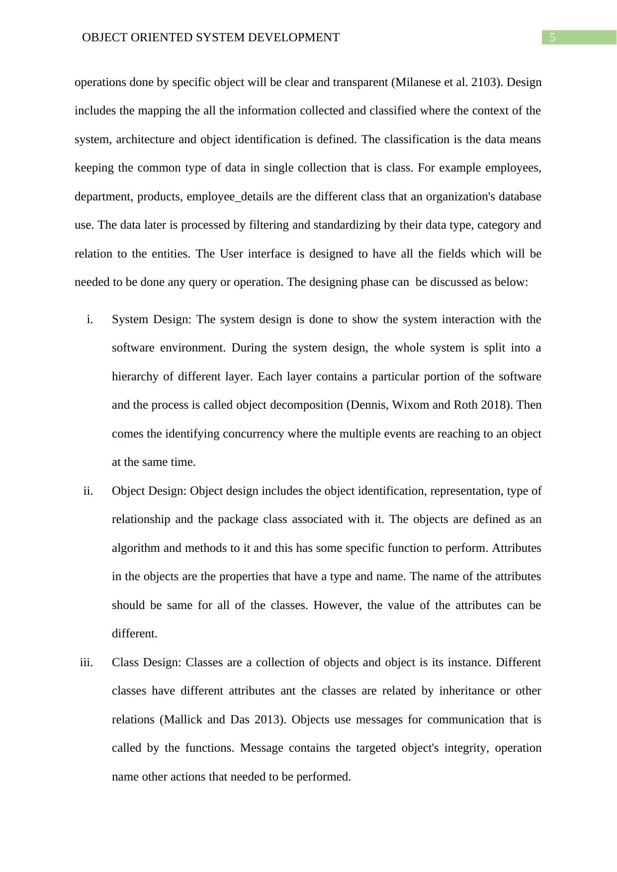
needed to be done any query or operation. The designing phase can be discussed as below:
i. System Design: The system design is done to show the system interaction with the
software environment. During the system design, the whole system is split into a
hierarchy of different layer. Each layer contains a particular portion of the software
and the process is called object decomposition (Dennis, Wixom and Roth 2018). Then
comes the identifying concurrency where the multiple events are reaching to an object
at the same time.
ii. Object Design: Object design includes the object identification, representation, type of
relationship and the package class associated with it. The objects are defined as an
algorithm and methods to it and this has some specific function to perform. Attributes
in the objects are the properties that have a type and name. The name of the attributes
should be same for all of the classes. However, the value of the attributes can be
different.
iii. Class Design: Classes are a collection of objects and object is its instance. Different
classes have different attributes ant the classes are related by inheritance or other
relations (Mallick and Das 2013). Objects use messages for communication that is
called by the functions. Message contains the targeted object's integrity, operation
name other actions that needed to be performed.
operations done by specific object will be clear and transparent (Milanese et al. 2103). Design
includes the mapping the all the information collected and classified where the context of the
system, architecture and object identification is defined. The classification is the data means
keeping the common type of data in single collection that is class. For example employees,
department, products, employee_details are the different class that an organization's database
use. The data later is processed by filtering and standardizing by their data type, category and
relation to the entities. The User interface is designed to have all the fields which will be
needed to be done any query or operation. The designing phase can be discussed as below:
i. System Design: The system design is done to show the system interaction with the
software environment. During the system design, the whole system is split into a
hierarchy of different layer. Each layer contains a particular portion of the software
and the process is called object decomposition (Dennis, Wixom and Roth 2018). Then
comes the identifying concurrency where the multiple events are reaching to an object
at the same time.
ii. Object Design: Object design includes the object identification, representation, type of
relationship and the package class associated with it. The objects are defined as an
algorithm and methods to it and this has some specific function to perform. Attributes
in the objects are the properties that have a type and name. The name of the attributes
should be same for all of the classes. However, the value of the attributes can be
different.
iii. Class Design: Classes are a collection of objects and object is its instance. Different
classes have different attributes ant the classes are related by inheritance or other
relations (Mallick and Das 2013). Objects use messages for communication that is
called by the functions. Message contains the targeted object's integrity, operation
name other actions that needed to be performed.
⊘ This is a preview!⊘
Do you want full access?
Subscribe today to unlock all pages.
Trusted by 1+ million students worldwide
6OBJECT ORIENTED SYSTEM DEVELOPMENT
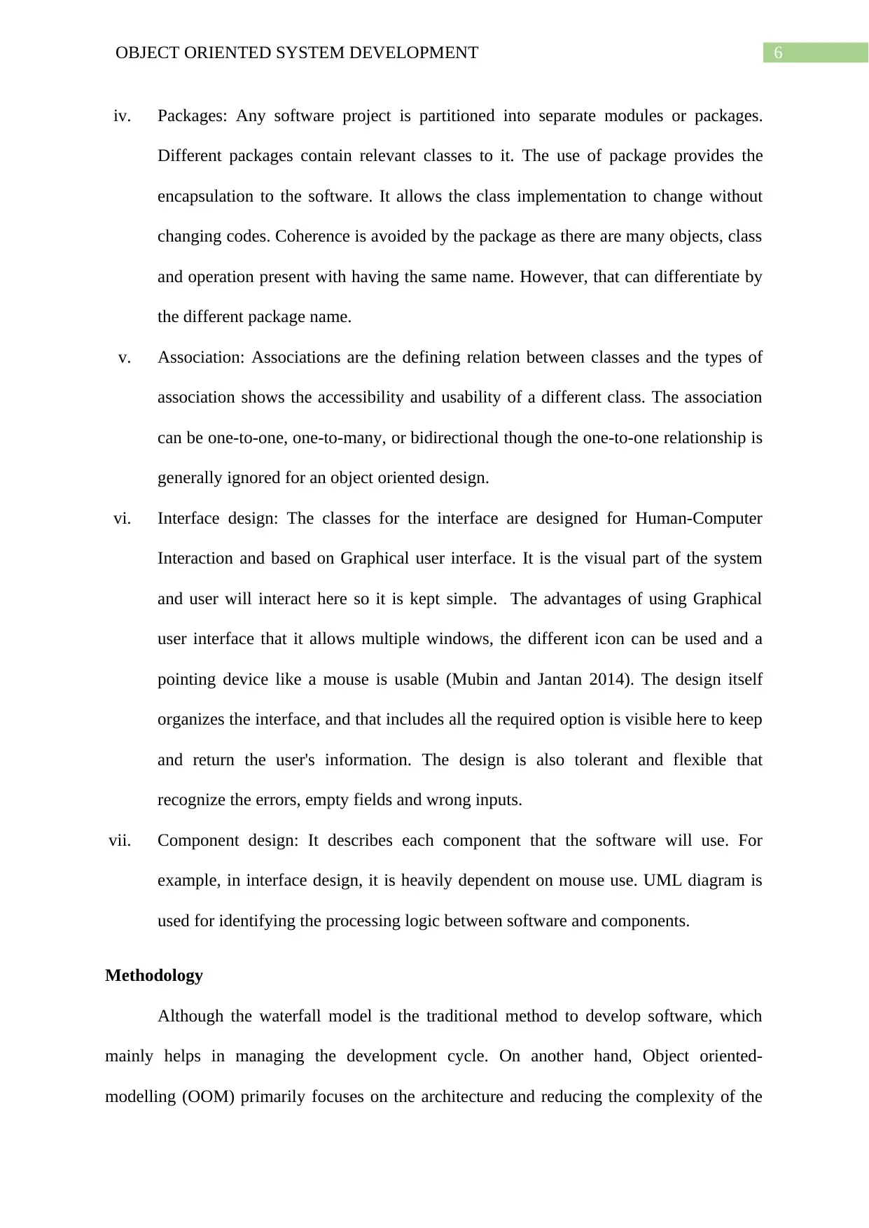
iv. Packages: Any software project is partitioned into separate modules or packages.
Different packages contain relevant classes to it. The use of package provides the
encapsulation to the software. It allows the class implementation to change without
changing codes. Coherence is avoided by the package as there are many objects, class
and operation present with having the same name. However, that can differentiate by
the different package name.
v. Association: Associations are the defining relation between classes and the types of
association shows the accessibility and usability of a different class. The association
can be one-to-one, one-to-many, or bidirectional though the one-to-one relationship is
generally ignored for an object oriented design.
vi. Interface design: The classes for the interface are designed for Human-Computer
Interaction and based on Graphical user interface. It is the visual part of the system
and user will interact here so it is kept simple. The advantages of using Graphical
user interface that it allows multiple windows, the different icon can be used and a
pointing device like a mouse is usable (Mubin and Jantan 2014). The design itself
organizes the interface, and that includes all the required option is visible here to keep
and return the user's information. The design is also tolerant and flexible that
recognize the errors, empty fields and wrong inputs.
vii. Component design: It describes each component that the software will use. For
example, in interface design, it is heavily dependent on mouse use. UML diagram is
used for identifying the processing logic between software and components.
Methodology
Although the waterfall model is the traditional method to develop software, which
mainly helps in managing the development cycle. On another hand, Object oriented-
modelling (OOM) primarily focuses on the architecture and reducing the complexity of the
Paraphrase This Document
Need a fresh take? Get an instant paraphrase of this document with our AI Paraphraser
7OBJECT ORIENTED SYSTEM DEVELOPMENT
software that will be developed (Adenowo and Adenowo 2013). This type of modelling uses
the real objects and their properties in the implementation part as objects. These objects are
later grouped and coded as class according to the design. In Object-oriented modelling,
Software design is mostly done by using UML (Unified Modelling Language). The Unified
Modelling is generally iterative in nature that is it works the bottom to up approach
(Gorschek, Tempero and Angelis 2014). It is also incremental and agile in nature where the
system keeps growing with time and agile means very light weighted approach. This method
allows using a real-life object to analyze and then design. It helps in specifying, constructing,
documenting and visualizing the object oriented programs. The UML method uses notations
for representing the relationships graphically. It also designs the decision and function
between the two classes. This is one type of early coding of the software as per requirements
and the design allows changes even after the completion. Currently, UML has 13 different
types of diagrams. For object oriented based diagrams, there many diagrams available like
class diagram, package diagram, object diagram, use case diagram, component diagram,
composite structure diagram and deployment diagram (Rumpe 2014). Some of the used
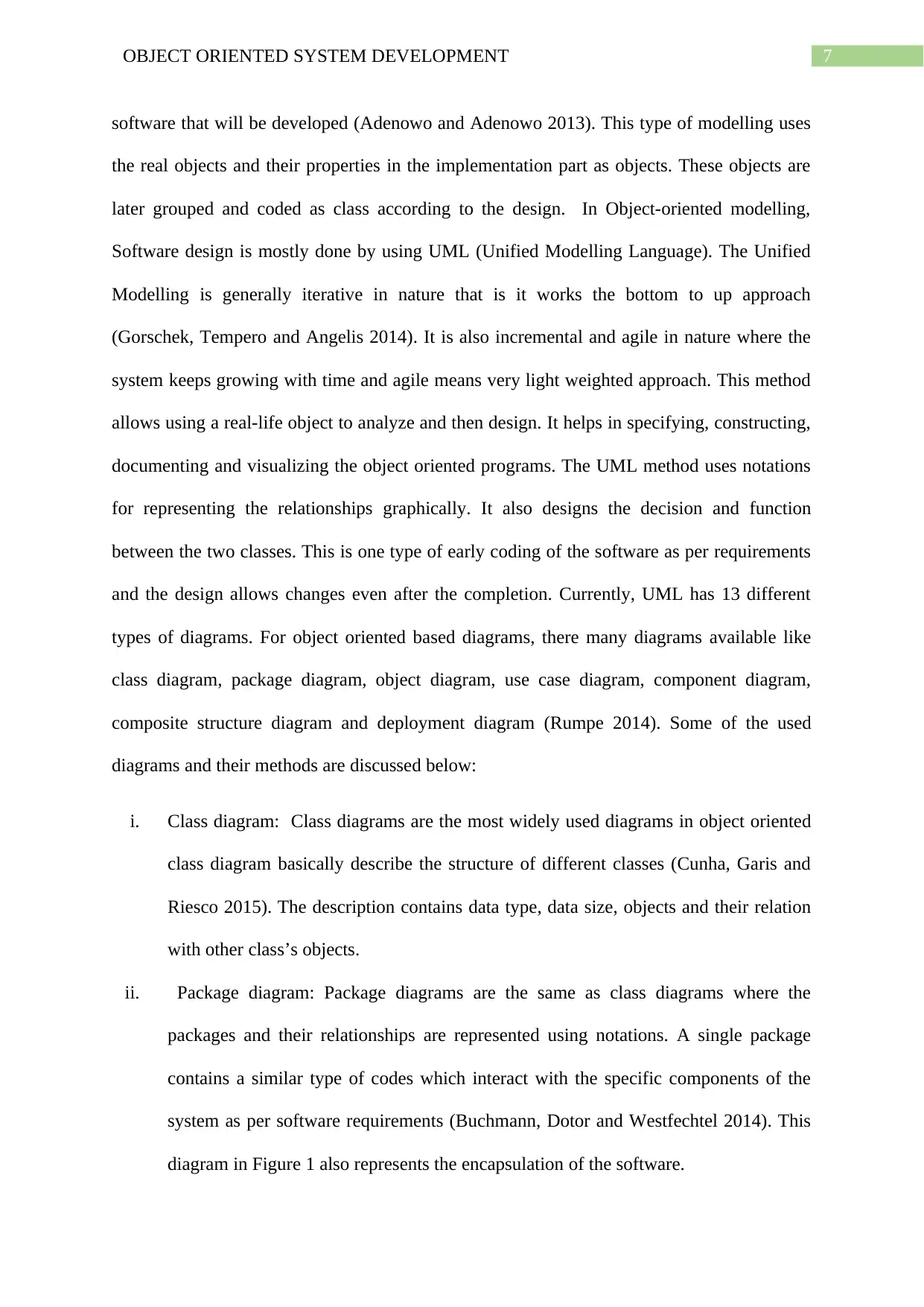
diagrams and their methods are discussed below:
i. Class diagram: Class diagrams are the most widely used diagrams in object oriented
class diagram basically describe the structure of different classes (Cunha, Garis and
Riesco 2015). The description contains data type, data size, objects and their relation
with other class’s objects.
ii. Package diagram: Package diagrams are the same as class diagrams where the
packages and their relationships are represented using notations. A single package
contains a similar type of codes which interact with the specific components of the
system as per software requirements (Buchmann, Dotor and Westfechtel 2014). This
diagram in Figure 1 also represents the encapsulation of the software.
software that will be developed (Adenowo and Adenowo 2013). This type of modelling uses
the real objects and their properties in the implementation part as objects. These objects are
later grouped and coded as class according to the design. In Object-oriented modelling,
Software design is mostly done by using UML (Unified Modelling Language). The Unified
Modelling is generally iterative in nature that is it works the bottom to up approach
(Gorschek, Tempero and Angelis 2014). It is also incremental and agile in nature where the
system keeps growing with time and agile means very light weighted approach. This method
allows using a real-life object to analyze and then design. It helps in specifying, constructing,
documenting and visualizing the object oriented programs. The UML method uses notations
for representing the relationships graphically. It also designs the decision and function
between the two classes. This is one type of early coding of the software as per requirements
and the design allows changes even after the completion. Currently, UML has 13 different
types of diagrams. For object oriented based diagrams, there many diagrams available like
class diagram, package diagram, object diagram, use case diagram, component diagram,
composite structure diagram and deployment diagram (Rumpe 2014). Some of the used
diagrams and their methods are discussed below:
i. Class diagram: Class diagrams are the most widely used diagrams in object oriented
class diagram basically describe the structure of different classes (Cunha, Garis and
Riesco 2015). The description contains data type, data size, objects and their relation
with other class’s objects.
ii. Package diagram: Package diagrams are the same as class diagrams where the
packages and their relationships are represented using notations. A single package
contains a similar type of codes which interact with the specific components of the
system as per software requirements (Buchmann, Dotor and Westfechtel 2014). This
diagram in Figure 1 also represents the encapsulation of the software.

8OBJECT ORIENTED SYSTEM DEVELOPMENT
Figure1: Package diagram
(Source: created by author)
iii. Object diagram: Object diagram describes structural relations between different
objects. Sometimes using inheritance, the same objects are called in different classes,
and then inheritance is obtained by connecting different classes using ‘extends’. It has
been used to testify to the class diagram.
iv. Use-case diagram: Only relationship and functions are not enough to predict the
development. The use-case diagram is used to see the dynamic behaviour of the
system (Al-alshuhai and Siewe 2015). However, for use-case diagrams, class
requirements are mostly designed. The functionalities are represented by use case and
actors are the real-world entities. Relationship between actors and use cases are
established using notations.
Using these different diagrams, the design has become more flexible and tolerant. The
design totally encapsulated the methods and attributes of the class, which will be required
next. Each method is fulfilling its service for that particular class. The same type of service is
⊘ This is a preview!⊘
Do you want full access?
Subscribe today to unlock all pages.
Trusted by 1+ million students worldwide
9OBJECT ORIENTED SYSTEM DEVELOPMENT
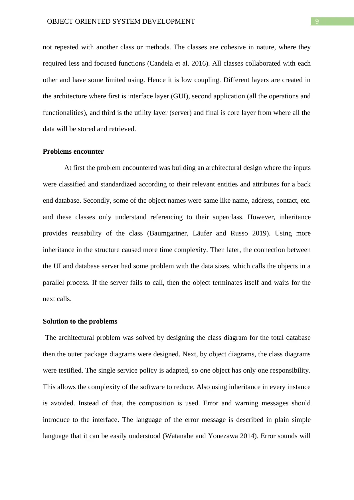
not repeated with another class or methods. The classes are cohesive in nature, where they
required less and focused functions (Candela et al. 2016). All classes collaborated with each
other and have some limited using. Hence it is low coupling. Different layers are created in
the architecture where first is interface layer (GUI), second application (all the operations and
functionalities), and third is the utility layer (server) and final is core layer from where all the
data will be stored and retrieved.
Problems encounter
At first the problem encountered was building an architectural design where the inputs
were classified and standardized according to their relevant entities and attributes for a back
end database. Secondly, some of the object names were same like name, address, contact, etc.
and these classes only understand referencing to their superclass. However, inheritance
provides reusability of the class (Baumgartner, Läufer and Russo 2019). Using more
inheritance in the structure caused more time complexity. Then later, the connection between
the UI and database server had some problem with the data sizes, which calls the objects in a
parallel process. If the server fails to call, then the object terminates itself and waits for the
next calls.
Solution to the problems
The architectural problem was solved by designing the class diagram for the total database
then the outer package diagrams were designed. Next, by object diagrams, the class diagrams
were testified. The single service policy is adapted, so one object has only one responsibility.
This allows the complexity of the software to reduce. Also using inheritance in every instance
is avoided. Instead of that, the composition is used. Error and warning messages should
introduce to the interface. The language of the error message is described in plain simple
language that it can be easily understood (Watanabe and Yonezawa 2014). Error sounds will
Paraphrase This Document
Need a fresh take? Get an instant paraphrase of this document with our AI Paraphraser
10OBJECT ORIENTED SYSTEM DEVELOPMENT
be introduced and different colour or type of sound will represent the type of warning or
error.
Performance on the basis of time variable.
When a system grows, the objects and input variables also increases. The tasks have
been done within time as it is the initial stage of the software. The inputs and the depth of the
relationships are much lesser from when the software will be in use (Galster et al. 2013).
However, more complex queries and operation which requires multiple functionalities raised
some problems that took more time to design where variability and length of the input
affected the response time of the system.
Testing of the design work
As the class diagrams were testified by the object relationship designs, the other designs
were tested by transforming the UML diagrams to behavioural diagrams such as sequence
diagrams for showing the interaction and sequences of operations between different layers of
the system and activity diagrams which shows the different stages and transition of the
operation (Jena, Swain and Mohapatra 2014). However, a use-case diagram also testified the
class and object diagrams for the system. In thread-based tests, classes are used as thread
where subsystem are integrated to the system. Overall testing is done by the verification-
validation process where the requirements of the output is verified (Sargent 2013). If it does
not meet the requirements, then it is validated. Testing is done in different phases first the
unit testing that is the subsystem testing, and then the integration testing of different layers
(system testing).
Conclusion
The amount of time spent on this design work is sufficient to see a full workflow of the
software. However, there are so many different aspects of choosing a different methodology
11OBJECT ORIENTED SYSTEM DEVELOPMENT
for object oriented design; the general objective to build software is fulfilled. The software is
also focused on the objects and their functionality, which is the main purpose of using object
oriented modelling. The object oriented design is providing better support for the hierarchy of
the classes. Apart from that, data abstraction, inheritance, encapsulation, and polymorphism
is implemented in the design. The next phase of the software will be creating a graphical user
interface.
Project Success
As per the objectives of the project, the design fits perfectly to the system.
The results of the testing phase, even facing some challenges and validation, are relevant to
the main goal of the software. As per the design the idea of abstraction, encapsulation,
polymorphism and inheritance, all there features are providing its features to the software.
The project is going to help the stakeholders of the company as they can see the employment
hierarchy of their organization and track the record of the employees’ details and information.
Personal Experience
This type of educational approach of active learning has helped to increase
the knowledge in this subject. Self-assessment of this project allows solving real-life
problems. From a personal point of view, the new things that have been learned is different
types of layering, diagrams, and graphical user interface and error handling.
Improvements suggestions
The main improvements for any object oriented design is to adding and staying close
to the idea of using only objects. By using many objects, the functional distribution will be
simpler and for discovering new function, new objects should be introduced. Another
suggestion is to take method names as verb so that it will be easier to differentiate between
methods and objects itself. The classes names should also use its parents class names as a
⊘ This is a preview!⊘
Do you want full access?
Subscribe today to unlock all pages.
Trusted by 1+ million students worldwide
1 out of 15
Related Documents


Your All-in-One AI-Powered Toolkit for Academic Success.
+13062052269
info@desklib.com
Available 24*7 on WhatsApp / Email
![[object Object]](/_next/static/media/star-bottom.7253800d.svg)
Unlock your academic potential
Copyright © 2020–2025 A2Z Services. All Rights Reserved. Developed and managed by ZUCOL.