Hydraulic Turbine Operation: Pelton, Francis, and Axial Analysis
VerifiedAdded on 2023/04/22
|6
|1196
|429
Report
AI Summary
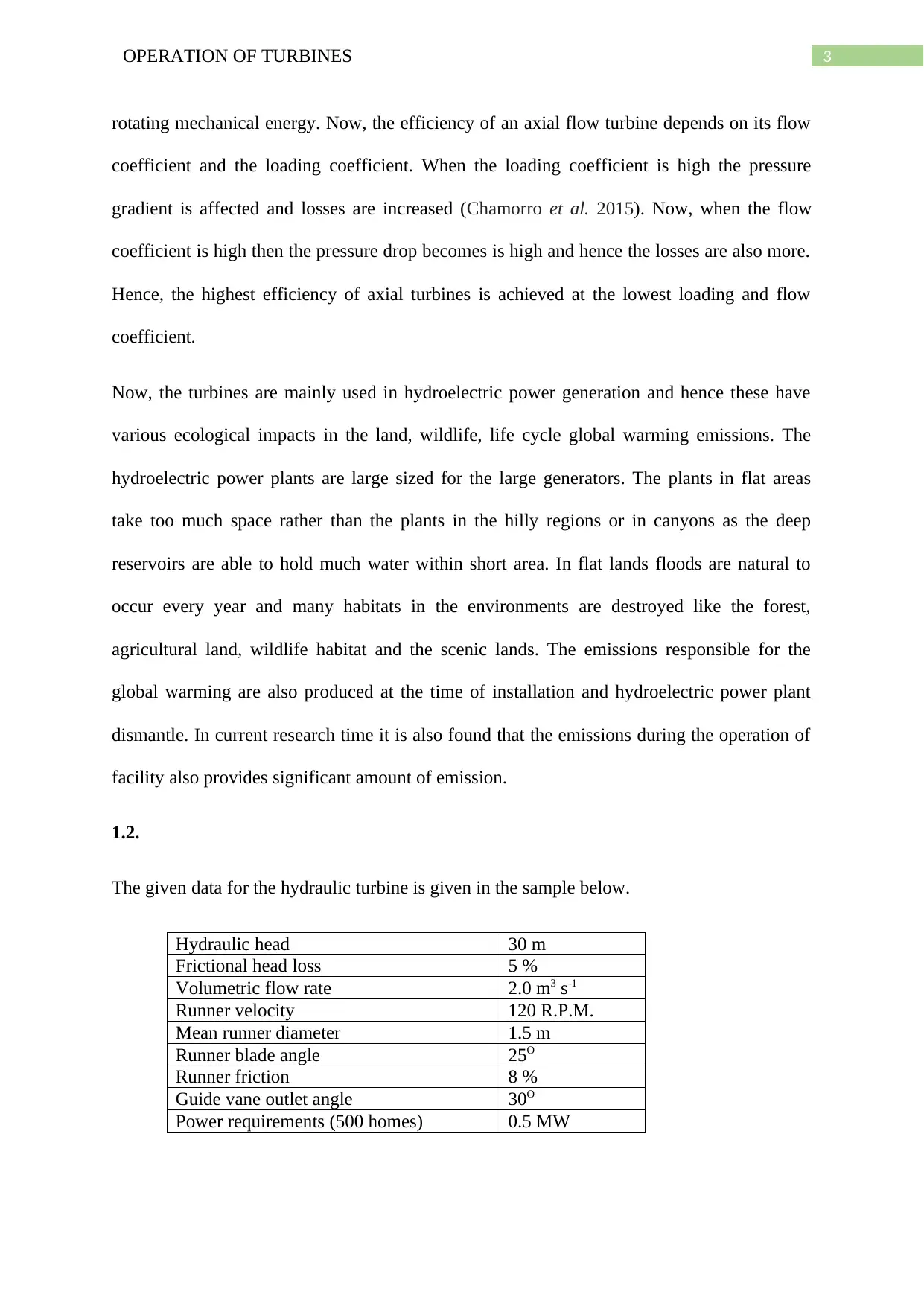
This report provides a detailed overview of the operation and analysis of hydraulic turbines, focusing on Pelton, Francis, and axial flow turbines. It begins with a description of the Pelton wheel, explaining its impulse-type design, efficiency, and limitations, such as the requirement for large operating heads. The report then examines the Francis turbine, a reaction turbine, discussing its blade efficiency calculation and its disadvantages, including high cost and complex design. The axial flow turbine is also discussed, highlighting its efficiency factors and its use in hydroelectric power generation. The report includes a sample hydraulic turbine data analysis, calculates hydraulic efficiency, and concludes with a discussion of the ecological impacts of hydroelectric power plants, such as habitat destruction and global warming emissions. The report references several relevant studies and provides a comprehensive understanding of turbine technology.

1 out of 6


Your All-in-One AI-Powered Toolkit for Academic Success.
+13062052269
info@desklib.com
Available 24*7 on WhatsApp / Email
![[object Object]](/_next/static/media/star-bottom.7253800d.svg)
Copyright © 2020–2026 A2Z Services. All Rights Reserved. Developed and managed by ZUCOL.