OPTIMISATION OF SHELL AND TUBE HEAT EXCHANGER 24.
VerifiedAdded on 2022/11/11
|45
|9969
|2
AI Summary
Optimisation of shell and tube heat exchanger
Contribute Materials
Your contribution can guide someone’s learning journey. Share your
documents today.
OPTIMISATION OF SHELL AND TUBE HEAT EXCHANGER i
M o u n t H e l e n C a m p u s
S c h o o l o f S c i e n c e , E n g i n e e r i n g a n d
I n f o r m a t i o n T e c h n o l o g y
Master of Engineering
Technology Degree
Research Project Thesis
2019
Optimization of Shell and
Tube Heat Exchanger
S u b m i t t e d b y :
S t u d e n t I D :
S t r e a m :
S u p e r v i s o r :
D a t e :
Secure Best Marks with AI Grader
Need help grading? Try our AI Grader for instant feedback on your assignments.
OPTIMISATION OF SHELL AND TUBE HEAT EXCHANGER ii
Acknowledgement:
Before starting with the research proposal, it’s with great pleasure to thank Dr.Ibrahim Sultan my
supervisor and advisor for his overwhelmingly help in the selection of topic and the fruitful
discussion which we had on the topic “Optimization of shell and tube heat exchanger”. Secondly I
share my gratitude to all friends who had all been part and parcel in helping me out in the successful
completion of my project proposal. It takes my immense privilege in proclaiming that without all
these people my project which includes the analysis of working of the Heat exchanger would all
have been in vain.
OPTIMISATION OF SHELL AND TUBE HEAT EXCHANGER iii
ABSTRACT.
Most if not all industrial processes in one way or another are associated with heat transfer in the
form of thermal energy differences in working fluids having thermal disparity. The device that
facilitates this thermal energy transfer is referred as heat exchanger. Heat exchangers are essential
in many industrial processes. Thus the productivity of any process is affected by the working
condition, status and overall efficiency of this device. Because of their importance, they widely
applied in chemical plants, mechanical manufacturing, air conditioning, and even refrigeration.
Shell and tube heat exchangers STHEs are most efficient exchanger of all types of heat exchangers,
and this has seen its application widen in different industrial applications such as chemical process,
power production industries, and refining plants. Most general solicitation of thermal transfer is in
designing of heat transfer apparatus for thermal exchange from fluid to another. Heat exchangers
are normally categorized concerning transfer process taking place in them
The objective of this project is to analyze performance efficiency of optimum shell and tube heat
exchangers through experimentation and software analysis (Naphon, 207). Design parameters are
formulated and computed in the form of optimization problems which are solved through Particle
Swarm Optimization (PSO). This optimization intends to reduce cost and expenses such as pumping
and area cost of these devices. All calculations and specification of the design parameters in this
paper are arrived at in consideration to Tubular Exchanger Manufacturers Association with pressure
drops and fouling limits. Values obtained in chapter four of this paper are considered most
appropriate in designing an optimized shell and tube heat exchanger. Verification results are also
listed providing proof of validation on the design calculations.
This report begins with bits of theory, providing general knowledge on heat exchanger with a
summarised introduction to heat exchangers. Overview of literature together with some recent
developments achieved towards optimization of heat exchangers. Matlab simulations and design
diagrams are also featured.
OPTIMISATION OF SHELL AND TUBE HEAT EXCHANGER iv
Table of Content
DECLARATION..................................................................................................................................i
ACKNOWLEDGEMENT:..................................................................................................................II
ABSTRACT........................................................................................................................................iii
List of figures………………………………………………………………………………………..
List of tables………………………………………………………………………………………….
Nomenclature……………………………………………………………………………………….
CHAPTER 1.........................................................................................................................................6
INTRODUCTION................................................................................................................................6
1.1 Background information.............................................................................................................6
1.2 Problem Statement.....................................................................................................................7
1.2.1 Selection of shell and tube heat exchanger:........................................................................8
1.2.2 Fixed tube heat exchanger.............................................................................................9
1.2.3 Removable type heat exchanger:.........................................................................................9
1.3 Classification of Heat Exchangers:....................................................................................10
1.3.1 Heat Exchanger Nomenclature:.........................................................................................11
1.3.2 Part names.........................................................................................................................11
CHAPTER TWO................................................................................................................................14
OVERVIEW OF OPTIMIZING SHELL AND TUBE HEAT EXCHANGER................................14
2.1 Overview of Heat Exchangers..................................................................................................14
2.1.1 The gravity film heat exchanger........................................................................................15
2.1.2 Plate Heat Exchangers.......................................................................................................15
2.1.3 Tube and Coil Drain Heat Recovery.................................................................................16
2.3 Existing heat exchangers..........................................................................................................16
2.3.1 Fixed tube sheet.................................................................................................................16
2.3.2 U-Tube...............................................................................................................................17
2.3.3Floating tubesheet...............................................................................................................17
2.4 Thermal Design Consideration:................................................................................................17
2.4.1 Shell design consideration:................................................................................................17
2.4.2 Tube design consideration:................................................................................................18
2.4.3 Tube pitch and tube layout:...............................................................................................18
2.4.4 Tube sheet design:.............................................................................................................18
2.4.5 Baffle Design:....................................................................................................................18
2.4.6 Valves………………………………………………………………………………………..
2.5 Two types of passes..................................................................................................................20
Secure Best Marks with AI Grader
Need help grading? Try our AI Grader for instant feedback on your assignments.
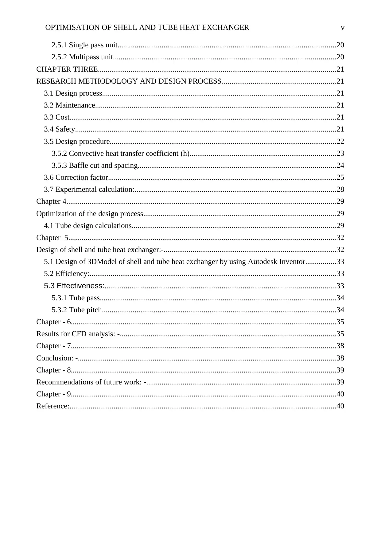
OPTIMISATION OF SHELL AND TUBE HEAT EXCHANGER v
2.5.1 Single pass unit..................................................................................................................20
2.5.2 Multipass unit....................................................................................................................20
CHAPTER THREE............................................................................................................................21
RESEARCH METHODOLOGY AND DESIGN PROCESS...........................................................21
3.1 Design process..........................................................................................................................21
3.2 Maintenance.............................................................................................................................21
3.3 Cost...........................................................................................................................................21
3.4 Safety........................................................................................................................................21
3.5 Design procedure......................................................................................................................22
3.5.2 Convective heat transfer coefficient (h)............................................................................23
3.5.3 Baffle cut and spacing.......................................................................................................24
3.6 Correction factor.......................................................................................................................25
3.7 Experimental calculation:.........................................................................................................28
Chapter 4............................................................................................................................................29
Optimization of the design process....................................................................................................29
4.1 Tube design calculations..........................................................................................................29
Chapter 5...........................................................................................................................................32
Design of shell and tube heat exchanger:-..........................................................................................32
5.1 Design of 3DModel of shell and tube heat exchanger by using Autodesk Inventor................33
5.2 Efficiency:................................................................................................................................33
5.3 Effectiveness:........................................................................................................................33
5.3.1 Tube pass...........................................................................................................................34
5.3.2 Tube pitch..........................................................................................................................34
Chapter - 6..........................................................................................................................................35
Results for CFD analysis: -................................................................................................................35
Chapter - 7..........................................................................................................................................38
Conclusion: -......................................................................................................................................38
Chapter - 8..........................................................................................................................................39
Recommendations of future work: -...................................................................................................39
Chapter - 9..........................................................................................................................................40
Reference:...........................................................................................................................................40
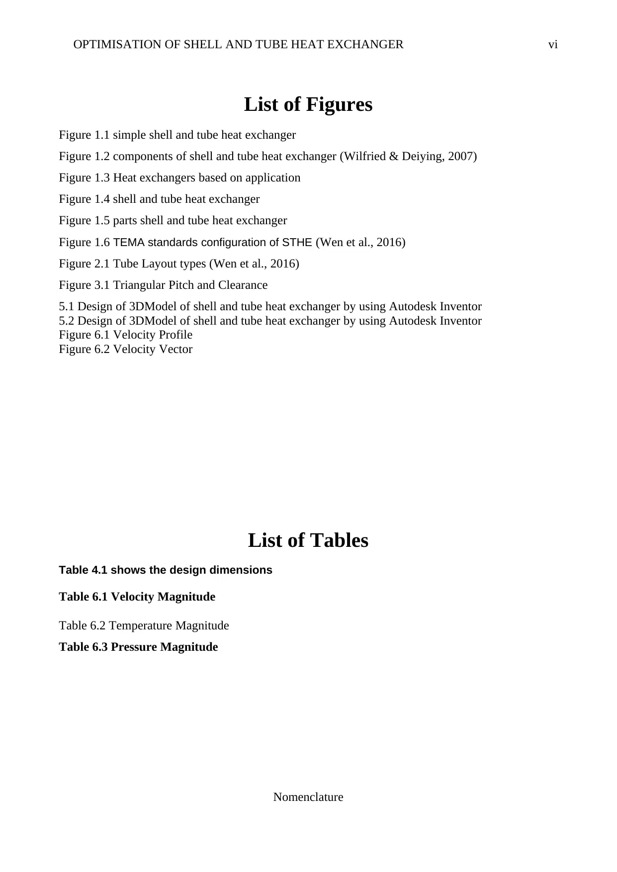
OPTIMISATION OF SHELL AND TUBE HEAT EXCHANGER vi
List of Figures
Figure 1.1 simple shell and tube heat exchanger
Figure 1.2 components of shell and tube heat exchanger (Wilfried & Deiying, 2007)
Figure 1.3 Heat exchangers based on application
Figure 1.4 shell and tube heat exchanger
Figure 1.5 parts shell and tube heat exchanger
Figure 1.6 TEMA standards configuration of STHE (Wen et al., 2016)
Figure 2.1 Tube Layout types (Wen et al., 2016)
Figure 3.1 Triangular Pitch and Clearance
5.1 Design of 3DModel of shell and tube heat exchanger by using Autodesk Inventor
5.2 Design of 3DModel of shell and tube heat exchanger by using Autodesk Inventor
Figure 6.1 Velocity Profile
Figure 6.2 Velocity Vector
List of Tables
Table 4.1 shows the design dimensions
Table 6.1 Velocity Magnitude
Table 6.2 Temperature Magnitude
Table 6.3 Pressure Magnitude
Nomenclature
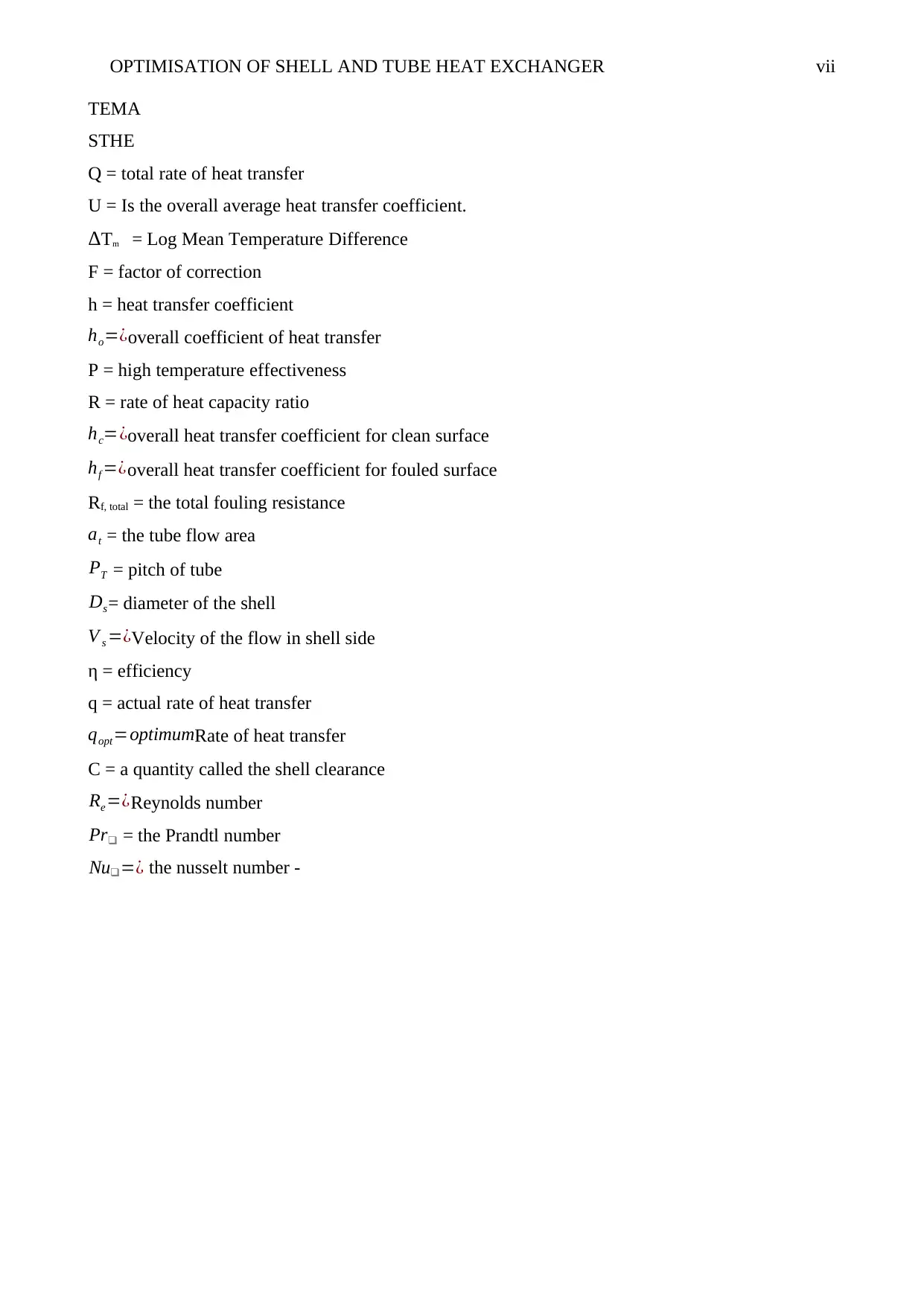
OPTIMISATION OF SHELL AND TUBE HEAT EXCHANGER vii
TEMA
STHE
Q = total rate of heat transfer
U = Is the overall average heat transfer coefficient.
ΔTm = Log Mean Temperature Difference
F = factor of correction
h = heat transfer coefficient
ho=¿overall coefficient of heat transfer
P = high temperature effectiveness
R = rate of heat capacity ratio
hc=¿overall heat transfer coefficient for clean surface
hf =¿overall heat transfer coefficient for fouled surface
Rf, total = the total fouling resistance
at = the tube flow area
PT = pitch of tube
Ds= diameter of the shell
V s =¿Velocity of the flow in shell side
η = efficiency
q = actual rate of heat transfer
qopt=optimumRate of heat transfer
C = a quantity called the shell clearance
Re=¿Reynolds number
Pr❑ = the Prandtl number
Nu❑=¿ the nusselt number -
Paraphrase This Document
Need a fresh take? Get an instant paraphrase of this document with our AI Paraphraser
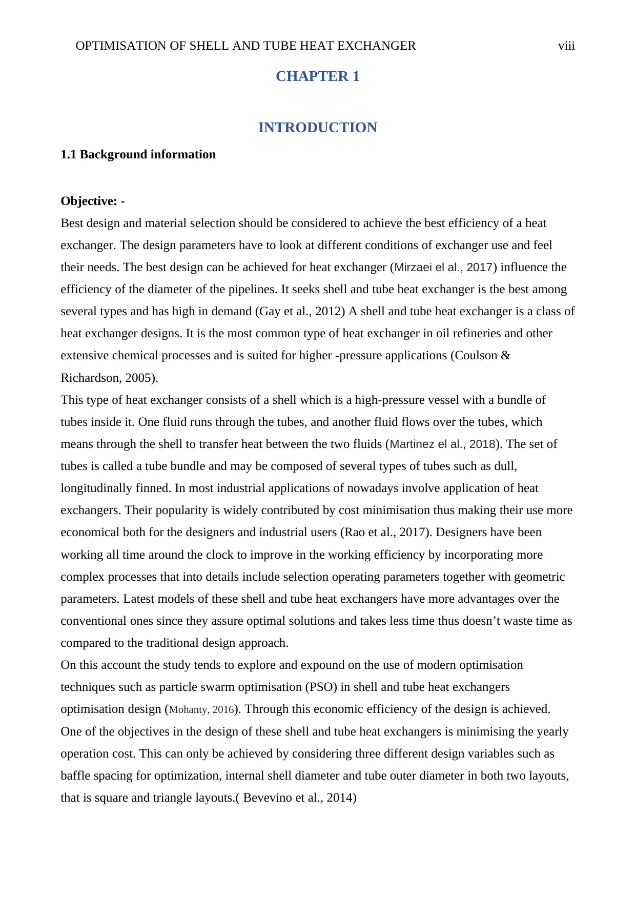
OPTIMISATION OF SHELL AND TUBE HEAT EXCHANGER viii
CHAPTER 1
INTRODUCTION
1.1 Background information
Objective: -
Best design and material selection should be considered to achieve the best efficiency of a heat
exchanger. The design parameters have to look at different conditions of exchanger use and feel
their needs. The best design can be achieved for heat exchanger (Mirzaei el al., 2017) influence the
efficiency of the diameter of the pipelines. It seeks shell and tube heat exchanger is the best among
several types and has high in demand (Gay et al., 2012) A shell and tube heat exchanger is a class of
heat exchanger designs. It is the most common type of heat exchanger in oil refineries and other
extensive chemical processes and is suited for higher -pressure applications (Coulson &
Richardson, 2005).
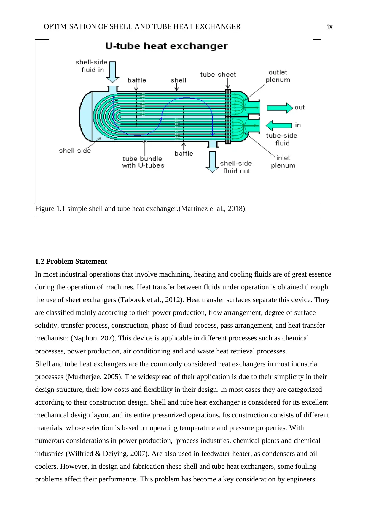
This type of heat exchanger consists of a shell which is a high-pressure vessel with a bundle of
tubes inside it. One fluid runs through the tubes, and another fluid flows over the tubes, which
means through the shell to transfer heat between the two fluids (Martinez el al., 2018). The set of
tubes is called a tube bundle and may be composed of several types of tubes such as dull,
longitudinally finned. In most industrial applications of nowadays involve application of heat
exchangers. Their popularity is widely contributed by cost minimisation thus making their use more
economical both for the designers and industrial users (Rao et al., 2017). Designers have been
working all time around the clock to improve in the working efficiency by incorporating more
complex processes that into details include selection operating parameters together with geometric
parameters. Latest models of these shell and tube heat exchangers have more advantages over the
conventional ones since they assure optimal solutions and takes less time thus doesn’t waste time as
compared to the traditional design approach.
On this account the study tends to explore and expound on the use of modern optimisation
techniques such as particle swarm optimisation (PSO) in shell and tube heat exchangers
optimisation design (Mohanty, 2016). Through this economic efficiency of the design is achieved.
One of the objectives in the design of these shell and tube heat exchangers is minimising the yearly
operation cost. This can only be achieved by considering three different design variables such as
baffle spacing for optimization, internal shell diameter and tube outer diameter in both two layouts,
that is square and triangle layouts.( Bevevino et al., 2014)
OPTIMISATION OF SHELL AND TUBE HEAT EXCHANGER ix
Figure 1.1 simple shell and tube heat exchanger.(Martinez el al., 2018).
1.2 Problem Statement
In most industrial operations that involve machining, heating and cooling fluids are of great essence
during the operation of machines. Heat transfer between fluids under operation is obtained through
the use of sheet exchangers (Taborek et al., 2012). Heat transfer surfaces separate this device. They
are classified mainly according to their power production, flow arrangement, degree of surface
solidity, transfer process, construction, phase of fluid process, pass arrangement, and heat transfer
mechanism (Naphon, 207). This device is applicable in different processes such as chemical
processes, power production, air conditioning and and waste heat retrieval processes.
Shell and tube heat exchangers are the commonly considered heat exchangers in most industrial
processes (Mukherjee, 2005). The widespread of their application is due to their simplicity in their
design structure, their low costs and flexibility in their design. In most cases they are categorized
according to their construction design. Shell and tube heat exchanger is considered for its excellent
mechanical design layout and its entire pressurized operations. Its construction consists of different
materials, whose selection is based on operating temperature and pressure properties. With
numerous considerations in power production, process industries, chemical plants and chemical
industries (Wilfried & Deiying, 2007). Are also used in feedwater heater, as condensers and oil
coolers. However, in design and fabrication these shell and tube heat exchangers, some fouling
problems affect their performance. This problem has become a key consideration by engineers
OPTIMISATION OF SHELL AND TUBE HEAT EXCHANGER x
trying to find the most suitable solution to this problem. Fouling refers to aggregation of
undesirable material deposition on surface of heat exchanger which decreases the rate of heat
transfer and increases the resistance to fluid flow, thus resulting unnecessary high-pressure drop
(Patel et al., 2012).
So, the transfer of heat from fluid to another is an critical process in chemical industries and
refrigeration industries. Shell and tube heat exchanger is one of the most efficient types of
equipment for this application. For chemical industries, chemical and water are two fluids whereas,
for refrigeration industries, refrigerant and water can be both fluids.
Main components of shell and tube heat exchanger are tubes, channel cover, channel, tubes sheets,
shell cover, baffle, and nozzle (Martinez el al., 2018).. Baffles are the plates that are fitted in the
sides of the shell to provide support to the tubes then direct flow across the shell side or along with
the tube bundle in a predefined manner, and the most commonly preferred are segmental baffles.
Segmental baffles are preferred since they improve transfer of heat by increasing fluid turbulence
and local mixing causing the fluid flow in a meander manner through tube bundle. It demands high
pumping power since it increases the pressure drop. The study on the effects of the focal distance
between the baffle spacing shows that the different spacing enhances the rate of thermal transfer
which is one of the most common problems encountered in these devices.( Martinez et al., 2018)
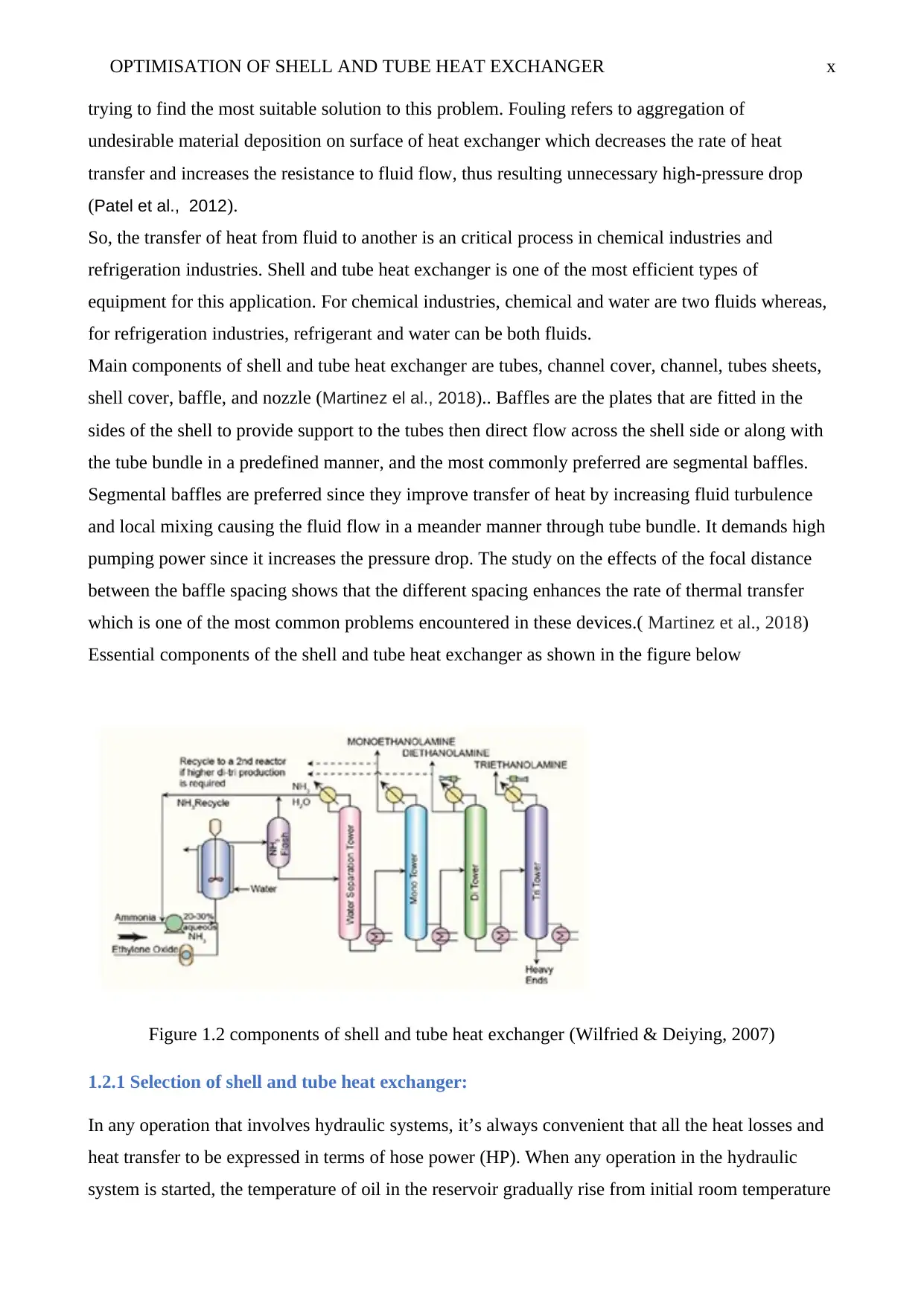
Essential components of the shell and tube heat exchanger as shown in the figure below
Figure 1.2 components of shell and tube heat exchanger (Wilfried & Deiying, 2007)
1.2.1 Selection of shell and tube heat exchanger:
In any operation that involves hydraulic systems, it’s always convenient that all the heat losses and
heat transfer to be expressed in terms of hose power (HP). When any operation in the hydraulic
system is started, the temperature of oil in the reservoir gradually rise from initial room temperature
Secure Best Marks with AI Grader
Need help grading? Try our AI Grader for instant feedback on your assignments.
OPTIMISATION OF SHELL AND TUBE HEAT EXCHANGER xi
that is ambient temperature to a leveling off temperature in a period that varies depending on the
process under consideration, the duty cycle, radiation of natural heat capability and type of system.
The oil temperature remains constant after this no matter how long the system remains in operation
unless specific changes and modifications are made in the duty cycle or the initial ambient
temperature (Martinez et al., 2018). The balance in the rate of heat is generation and rate at which
system can dispose heat by natural cooling radiation reached this temperature. No heat exchange
expected if the leveling off temperature is low enough to an acceptable level since the primary
purpose of shell and tube heat exchanger reduces leveling off temperature to acceptable
recommended level.
In hydraulic systems, heat radiated from all its metallic components that including cylinders, motor,
valves, oil reservoir and from steel fitting and iron fittings. In most low power systems, natural
radiation is adequate to maintain the leveling off temperature to acceptable recommended level
most so when the duct cycle involved is short (Wilfried & Deiying, 2007). However, on larger
power systems the area of the surfaces radiating heat is more or less in proportions to power
systems. Thus exchangers are needed in such large systems to avoid high leveling off temperature.
Before shell and tube heat exchanger selected, it is necessary to have estimation of the probable
system losses, which eventually will turn up as heat and must be disposed by heat exchanger with
the help of natural radiation. It’s often rare that these losses can accurately be computed and
calculated therefore the designing engineer is expected to rely on standards information and should
make the selection of heat exchanger that will provide sufficient capacity (Martinez et al., 2018).
There are two types of heat exchanger categorized as -
1.2.2 Fixed-tube type heat exchangers:
These are the cheapest heat exchanger, here the tube sheets are welded on shells and cannot be
removed during maintenance, and their simplicity in design makes them economical in
construction. For cleaning purpose particular type tools are required, cleaning of their tube bores
can be done either chemically or mechanically (Patel et al 2012).. These kinds of heat exchangers
are used where the fluids are non-corrosive. In this type when the temperatures difference exists
between tube materials and shells it will demand incorporation of bellows in the shell to allow
expansion that facilitates the elimination of excess stresses. Bellows are mostly source of weakness
and failure during operation.
OPTIMISATION OF SHELL AND TUBE HEAT EXCHANGER xii
1.2.3 Removable type heat exchanger:
They are a bit costly. The tube sheet can be removed from shell also there will be difficulty in
leakage arrest of the fluid through different cross-section. These categories of heat exchangers can
be fluctuating head type or U-tube type. U-tube heat exchangers any front header types may be
used, and the rare header is always an M-type. It allows unrestricted thermal expansion thus the
tube bundle can easily be cleaned since they can be removed (Patel et al 2012)..
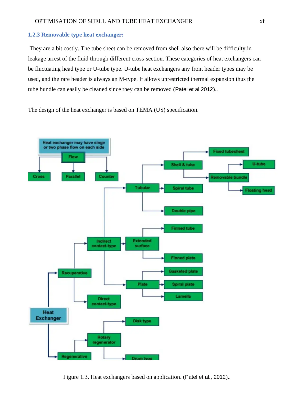
The design of the heat exchanger is based on TEMA (US) specification.
Figure 1.3. Heat exchangers based on application. (Patel et al., 2012)..
OPTIMISATION OF SHELL AND TUBE HEAT EXCHANGER xiii
1.3 Classification of Heat Exchangers
,
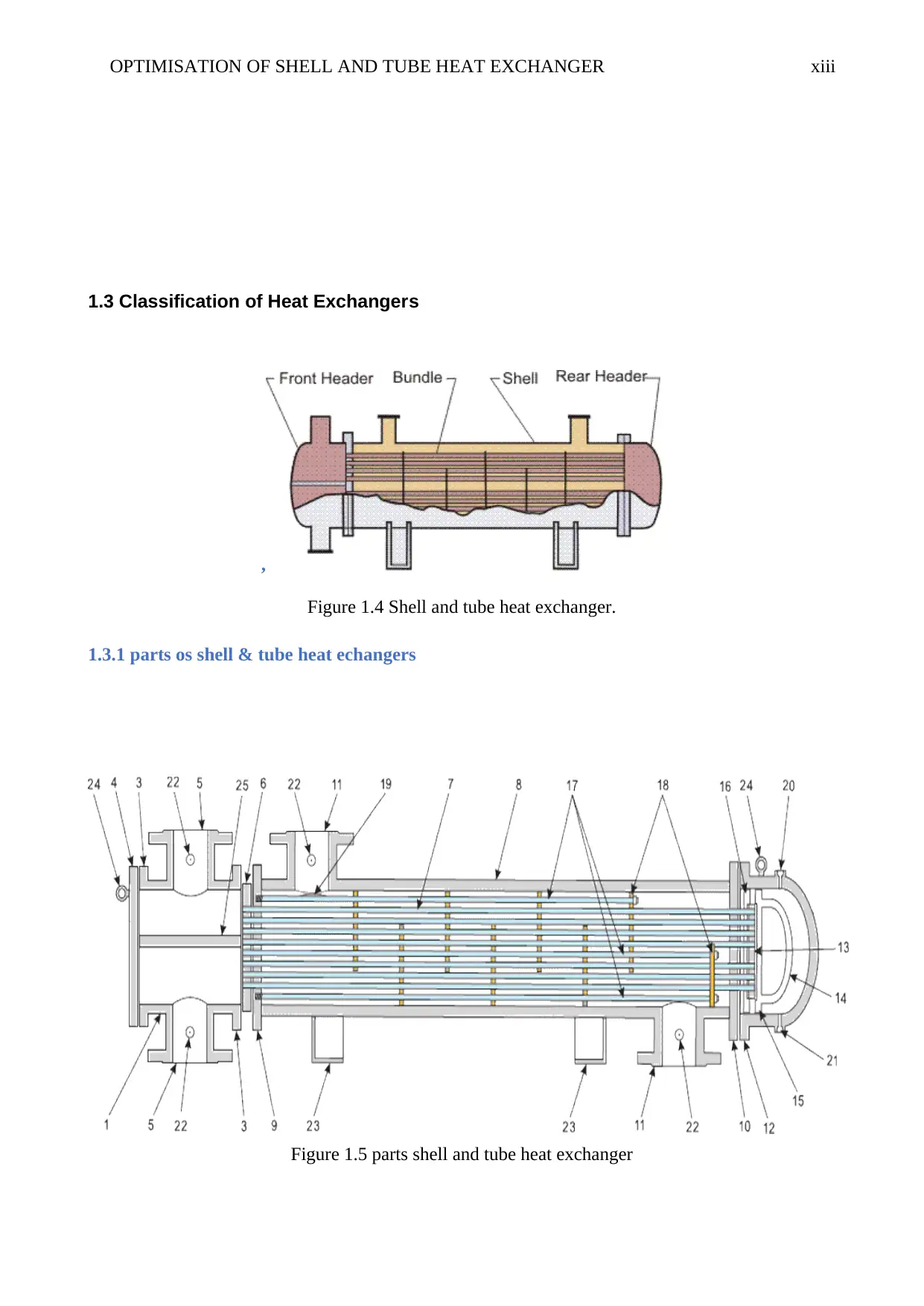
Figure 1.4 Shell and tube heat exchanger.
1.3.1 parts os shell & tube heat echangers
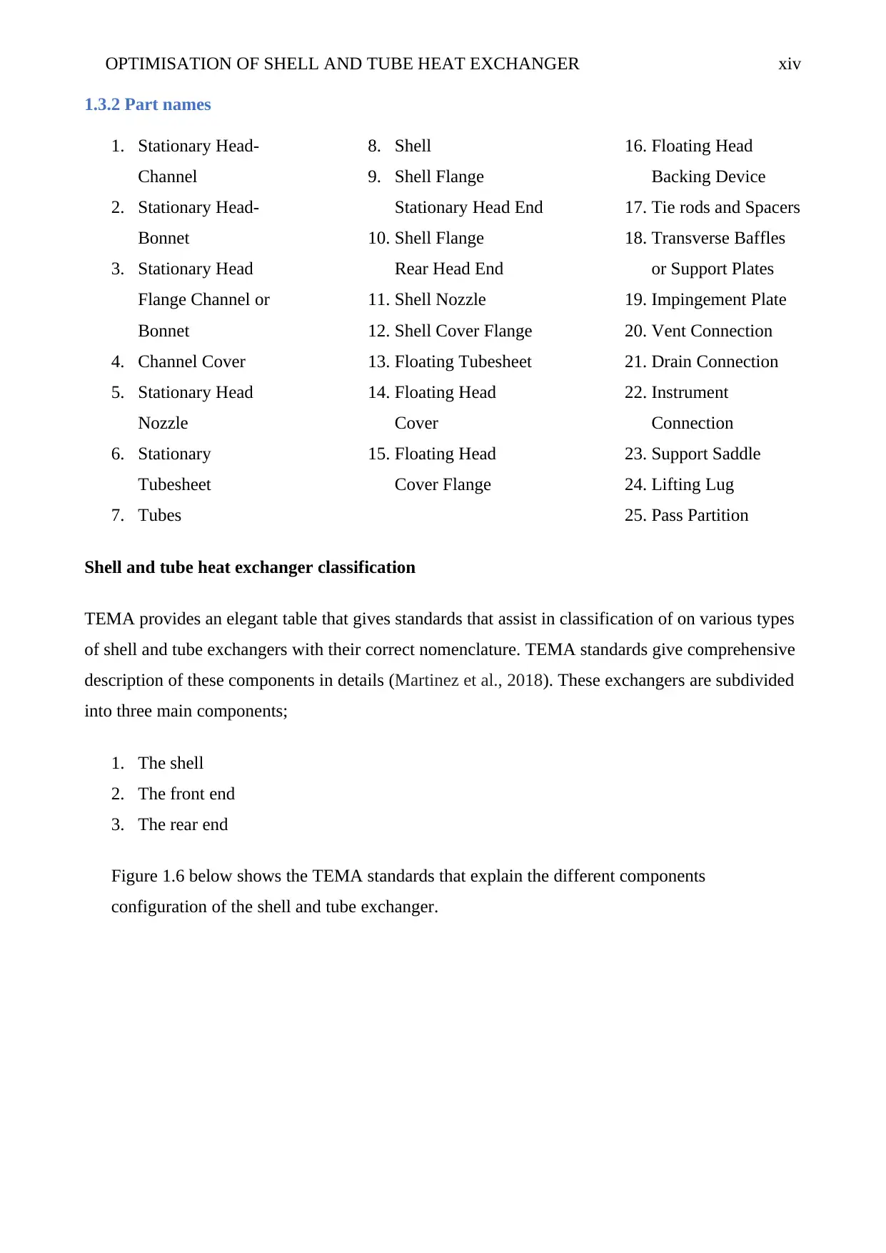
Figure 1.5 parts shell and tube heat exchanger
1.3 Classification of Heat Exchangers
,
Figure 1.4 Shell and tube heat exchanger.
1.3.1 parts os shell & tube heat echangers
Figure 1.5 parts shell and tube heat exchanger
Paraphrase This Document
Need a fresh take? Get an instant paraphrase of this document with our AI Paraphraser
OPTIMISATION OF SHELL AND TUBE HEAT EXCHANGER xiv
1.3.2 Part names
1. Stationary Head-
Channel
2. Stationary Head-
Bonnet
3. Stationary Head
Flange Channel or
Bonnet
4. Channel Cover
5. Stationary Head
Nozzle
6. Stationary
Tubesheet
7. Tubes
8. Shell
9. Shell Flange
Stationary Head End
10. Shell Flange
Rear Head End
11. Shell Nozzle
12. Shell Cover Flange
13. Floating Tubesheet
14. Floating Head
Cover
15. Floating Head
Cover Flange
16. Floating Head
Backing Device
17. Tie rods and Spacers
18. Transverse Baffles
or Support Plates
19. Impingement Plate
20. Vent Connection
21. Drain Connection
22. Instrument
Connection
23. Support Saddle
24. Lifting Lug
25. Pass Partition
Shell and tube heat exchanger classification
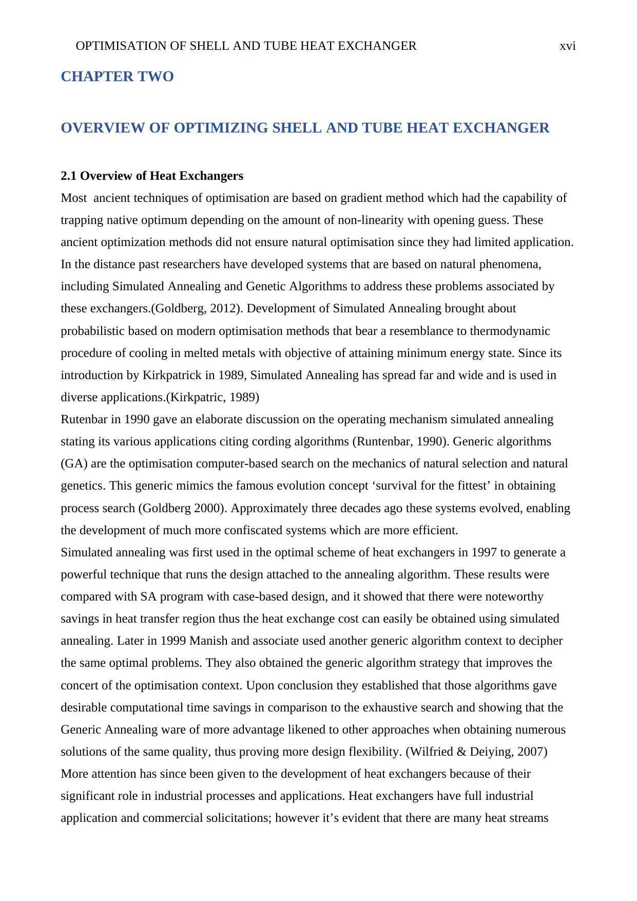
TEMA provides an elegant table that gives standards that assist in classification of on various types
of shell and tube exchangers with their correct nomenclature. TEMA standards give comprehensive
description of these components in details (Martinez et al., 2018). These exchangers are subdivided
into three main components;
1. The shell
2. The front end
3. The rear end
Figure 1.6 below shows the TEMA standards that explain the different components
configuration of the shell and tube exchanger.
OPTIMISATION OF SHELL AND TUBE HEAT EXCHANGER xv
Figure 1.6 TEMA standards configuration of STHE (Wen et al., 2016)
Figure 1.6 TEMA standards configuration of STHE (Wen et al., 2016)
OPTIMISATION OF SHELL AND TUBE HEAT EXCHANGER xvi
CHAPTER TWO
OVERVIEW OF OPTIMIZING SHELL AND TUBE HEAT EXCHANGER
2.1 Overview of Heat Exchangers
Most ancient techniques of optimisation are based on gradient method which had the capability of
trapping native optimum depending on the amount of non-linearity with opening guess. These
ancient optimization methods did not ensure natural optimisation since they had limited application.
In the distance past researchers have developed systems that are based on natural phenomena,
including Simulated Annealing and Genetic Algorithms to address these problems associated by
these exchangers.(Goldberg, 2012). Development of Simulated Annealing brought about
probabilistic based on modern optimisation methods that bear a resemblance to thermodynamic
procedure of cooling in melted metals with objective of attaining minimum energy state. Since its
introduction by Kirkpatrick in 1989, Simulated Annealing has spread far and wide and is used in
diverse applications.(Kirkpatric, 1989)
Rutenbar in 1990 gave an elaborate discussion on the operating mechanism simulated annealing
stating its various applications citing cording algorithms (Runtenbar, 1990). Generic algorithms
(GA) are the optimisation computer-based search on the mechanics of natural selection and natural
genetics. This generic mimics the famous evolution concept ‘survival for the fittest’ in obtaining
process search (Goldberg 2000). Approximately three decades ago these systems evolved, enabling
the development of much more confiscated systems which are more efficient.
Simulated annealing was first used in the optimal scheme of heat exchangers in 1997 to generate a
powerful technique that runs the design attached to the annealing algorithm. These results were
compared with SA program with case-based design, and it showed that there were noteworthy
savings in heat transfer region thus the heat exchange cost can easily be obtained using simulated
annealing. Later in 1999 Manish and associate used another generic algorithm context to decipher
the same optimal problems. They also obtained the generic algorithm strategy that improves the
concert of the optimisation context. Upon conclusion they established that those algorithms gave
desirable computational time savings in comparison to the exhaustive search and showing that the
Generic Annealing ware of more advantage likened to other approaches when obtaining numerous
solutions of the same quality, thus proving more design flexibility. (Wilfried & Deiying, 2007)
More attention has since been given to the development of heat exchangers because of their
significant role in industrial processes and applications. Heat exchangers have full industrial
application and commercial solicitations; however it’s evident that there are many heat streams
Secure Best Marks with AI Grader
Need help grading? Try our AI Grader for instant feedback on your assignments.
OPTIMISATION OF SHELL AND TUBE HEAT EXCHANGER xvii
disregarded, such as large amount of heat energy that is wasted through adjacent systems such as
drain plumbing systems (Patel et al 2012). The course of heat transfer over one fluid to another in
heat exchangers is commonly based on simple chattels of heat conditions. Considering two
autonomous chambers and circuits both involving fluids at varying temperature, the heat is always
transferred to cold region trying to obtain equilibrium. Two crucial aspects contribute to the
efficiency of heat transfer that is, type of material used in heat conduction and amount of outside
area contacted by heat source.
Over the past decades, there has been advancement in heat exchanger technology penetrating the
industrial market worldwide. In the same magnitude, the advances in techniques with increasing
interest cost-benefit analysis of the efficient custom of energy properties together with other
resource controlling policies. The efforts are within the mechanical and plumbing systems to ensure
efficient heat management in transforming ‘waste stream’ to resource commodity.
2.1.1 The gravity film heat exchanger
Gravity film exchanger (GFX) is made up of tubes with coil drains coupled by heat recovery system
works in resemblance to plumbing device. These are well-engineered plumbing devices that
facilitated transfer of heat from the drain water to incoming preheat water over a mechanically
copper supply line wrapped in coiling around copper tubes (Martinez et al., 2018). The key factor
influencing the effective heat transfer is the surface area with the squeaky falling flick of drain
water. In cases where the wastewater drains through a vertical tube, the drain water cannot flow
down to the centre; instead it cleaves on the surface of drain water pipes as it dislodges the air
within the pipe and taking the path of the least resistance regarding natural properties of surface
tension. The wastewater flows down the inner wall of the pipe a thin turbulent film, allowing
efficient heat transfer (Patel et al 2012).
2.1.2 Plate Heat Exchangers
This exchanger is commonly referred to as PHE. They involve series of construction of flat plates
that are engraved with channels. Plates are then slanted in such a manner that they form a
multidimensional alternating path for clear fluid to flow over. Every circuit is attached to inlet and
outlet through manifolds at each end. The advantage of PHEs is the design that minimises the
surface area thus providing more excellent heat dissipation. These plate heat exchangers are broadly
classified into two categories depending on their construction style; either plate and frame or brazed
plate. (Wen et al., 2016) Generally they are constructed with stainless steel that counterattack
corrosion and are cost operative and squashed in size owing to their great amount of outside area.
OPTIMISATION OF SHELL AND TUBE HEAT EXCHANGER xviii
Both of the two systems apply the same properties of heat condition, but there is slight in shape and
their application.
2.1.3 Tube and Coil Drain Heat Recovery
There is much energy contained in the drain water, and this energy is captured by Drain heat
recovery (DHR) that would or else be lost into drain system. Most cradles include clothes washers,
showers, dishwashers and sinks. International energy’s statistics administration had projected that in
1995, domestic water heaters consumed about 740 billion KWh of energy and 320 billion KWh of
energy consumed by commercial water heater (Wen et al., 2016). From this research, it showed that
approximately 87% of this energy is wasted down the gutter carrying through its billions of KWh
and billions of dollars. Endless efforts are made to ensure that this energy doesn’t go to waste; tube
and coil GFX system contribute significantly in the saving of this energy (Martinez et al., 2018). As
warm water flows down the trench, GFX tap and efficiently relocate heat to the walls of copper
sewer line to the icy water as it continuously flows up oversupply loop. The quantity of heat
transferred to cold supply system depends on the size, amount and shape of the system.
Winkler Development is developing Troutdale Terrace and designed by Sullivan Architecture. This
project was the largest in chains of fittings involving GFX drain heat recovery with some of the
installation have been established for commercial laundries, single-family residences, salons, flight-
type commercial dishwasher and even gymnasiums. (Rao et al., 2017)
2.2 Classification of Heat Exchanger
The heat exchangers are classified as:
Recuperates and Regenerators
The direct contact transfer and indirect contact transfer processes.
Based on geometry as tubes, plates and extended surfaces.
The heat transfer mechanisms as single-phase and two-phase flows.
Based on the flow arrangement as parallel flow, counter flow and crossflow.
2.3 Existing heat exchangers
2.3.1 Fixed tube sheet
In this type of heat, the exchanger has two fixed plates embedded at both ends of the tube
bundle. Its advantage is that it is the most economical in terms of fabrication with minimising
jacketed gaskets thus reducing possibilities of leakage. On the other hand, on its demerit is that
the tube of the bundle cannot be physically inspected or mechanically cleaned and insignificant
OPTIMISATION OF SHELL AND TUBE HEAT EXCHANGER xix
temperature difference it is associated with structural faults usually caused by thermal expansion
between the tube bundle and the shell.
2.3.2 U-Tube
In this type of heat exchanger, there is one tubesheet supporting all the available tube that are
oriented in U-shape hance, returning the fluid to the stationary head (Martinez et al., 2018). Its
merit over other types is that it is capable of handling high pressure and temperature fluid
circulation in the tubes and its ability to absorb thermal expansion at low cost. On its
disadvantage with this kind of heat exchanger, its difficult do cleaning of the internal parts of
the tube mechanically and has limited passes in the tube side.
2.3.3Floating tube sheet
These exchangers are a combination of the fixed tube sheet and U-tube heat exchangers in
structure and design even though the tubes are not U-shaped, the fluid flows back to the
stationary head due to the presence of floating head designed at the periphery of the tube
bundle. This configuration is the best suitable option for the inspection repair and maintenance,
and it allows the elimination of differential thermal expansion effects that may exist in between
the shell and tube bundles. Its manufacturing expenses are quite expensive because of its
complex configuration and numerous jacketed gaskets. (Wen et al., 2016)
2.4 Thermal Design Consideration:
For design of pipes we need to study heat transfer range, quantity of tubes, tube length, diameter,
layout, tube pitch, quantity of baffles, shell and tube pass and pressure drop through the shell and
tube.
2.4.1 Shell design consideration:
In the design and construction of the shell, TEMA shell-type E since it is most appropriate for
industrial processes that involve cooling solicitations (Wen et al., 2016). However, for some
applications other shell types have distinct advantages. For example, in case of heat transfer, TEMA
F design type is most applicable since it provides longitudinal plates that are installed inside tube
bundle assembly. These flow plates enable the shell fluid move down one half of the tube bundle,
the down the remaining half thus producing a counter-current flow partner. This type of
construction is mostly considered where close approach temperature is of essence and when the rate
of flow permits the utilisation of one half of the shell at a time. In amplifications that involve heat
Paraphrase This Document
Need a fresh take? Get an instant paraphrase of this document with our AI Paraphraser
OPTIMISATION OF SHELL AND TUBE HEAT EXCHANGER xx
recovery or when the operation demands for prolonged thermal length to obtain effective overall
heat transfer, then it is recommended to install the shells with the flows in series. (Wilfried &
Deiying, 2007)
The tube bundle is placed in the shell. This is fabricated from the steel pipe. The primary
consideration is the distance between the tube and shell interior wall.
2.4.2 Tube design consideration:
The OD of the tube is fabricated from 3/4” and 1” pipe. This is designed to maximise number of
tubes in order to increase turbulence. Also, wideness of tubes are designed to withstand the inner
pressure.
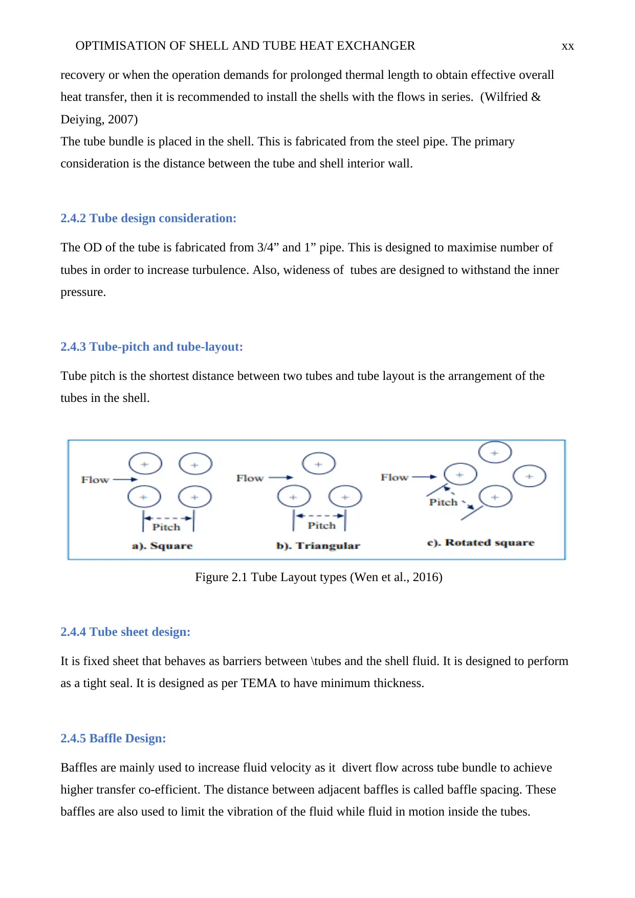
2.4.3 Tube-pitch and tube-layout:
Tube pitch is the shortest distance between two tubes and tube layout is the arrangement of the
tubes in the shell.
Figure 2.1 Tube Layout types (Wen et al., 2016)
2.4.4 Tube sheet design:
It is fixed sheet that behaves as barriers between \tubes and the shell fluid. It is designed to perform
as a tight seal. It is designed as per TEMA to have minimum thickness.
2.4.5 Baffle Design:
Baffles are mainly used to increase fluid velocity as it divert flow across tube bundle to achieve
higher transfer co-efficient. The distance between adjacent baffles is called baffle spacing. These
baffles are also used to limit the vibration of the fluid while fluid in motion inside the tubes.
OPTIMISATION OF SHELL AND TUBE HEAT EXCHANGER xxi
2.4.6 Valves –
Isolation valve - this valve may be located inside and outside of heat exchanger. It is open to
place the unit in operation and it is closed to isolate the unit when it is taken out of service
(Martinez et al., 2018).
Drain valves - Many heat exchangers also have drain valves, and these valves are used to
remove fluid from heat exchanger when unit is shut down.
Vent valves - vent valves are also found on the heat exchanger and are used to remove air or
other undesirable gases from heat exchanger. If pockets of air or gas are trapped inside the
unit, they can prevent process fluids from coming into contact with some of the tubes when
this happens the heat exchanger won't be able to transfer heat properly. So these pockets
reduce the heat exchanger efficiency and can produce hot spots. A hot spot is an area in the
heat exchanger where temperature becomes excessive these areas of high temperature can
damage the heat exchanger.
Relief Valve - Relief valve is commonly found in most heat exchangers. It is used to prevent
over pressurising heat exchanger. If the pressure exceeds a preset limit then the relief valve
opens to relieve the pressure, and the relief valve will remain open until the pressure falls
below the preset limit.
Control Valve - These valves are used to regulate the flow of fluids through a heat
exchanger. For example, the flow of the heating or cooling fluid is often regulated to control
the temperature of the process fluid leaving the heat exchanger in this system. The control
valve is linked through an instrument system to a device that senses the outlet temperature
of the fluid as the fluid temperature changes the sensing device sends a signal through a
controller to the control valve actuator which opens or closes the control valve and regulates
flow to maintain desired temperature. (Rao et al., 2017)
Generally, an operator can observe instruments to determine if the heat exchanger is
operating correctly. These instruments are often located in the control room, but they may
also be found on or near the heat exchanger depending on its use.
Pressure and temperature gauges - It may be placed on any or all of the heat exchangers
inlets and outlets on the heat exchanger that uses steam an auxiliary device called a steam
OPTIMISATION OF SHELL AND TUBE HEAT EXCHANGER xxii
trap drain water or condensate from the steam in the heat exchanger without letting the
steam escape lost steam reduces the efficiency of heat exchanger.
2.5 Two types of passes
2.5.1 Single pass unit
The fluid on the tube side enters one head and exits from other head and the shell side fluid
enters the heat exchanger which flows in the opposite direction and exits out. Two fluids
pass each other only once.
2.5.2 Multipass unit
In this unit, this tube side fluid passes the shell side fluid twice. The tube side fluid enters
from one side and is directed through half of the tubes by the inlet head after passing
through the first half of the tubes then the fluid is directed into the rest of the tubes by the
return head, the fluid then passes through the rest of the tubes and is directed out of the heat
exchanger besides the number of passes the flow paths inside a heat exchanger can also be
used to categorize heat exchangers
Secure Best Marks with AI Grader
Need help grading? Try our AI Grader for instant feedback on your assignments.
OPTIMISATION OF SHELL AND TUBE HEAT EXCHANGER xxiii
CHAPTER THREE
RESEARCH METHODOLOGY AND DESIGN PROCESS
The design of optimal tube exchangers is achieved through using the following approaches and
methodology arrived at after thorough scrutiny.
3.1 Design process
The following considerations ought to be met by in design of heat exchanger. The machine should
be easy to operate; it should be automatic, i.e. the operator only needs to do the initial installation
and to set to verify that the equipment in moved. Optimised shell and tube heat exchanger need be
economical to fabricate as cheap and locally available materials should be used in fabrication
(Martinez et al., 2018). The regular workshop, advanced mechanical engineering workshop,
welding and fabrication workshop will be used. The machine should be easy to maintain and
operate as the designed should allow quick and easy servicing. Considering ergonomics; the
machine will be designed in such a way that health problems to the operator are minimized. The
equipment should not pose any environmental risk and should not produce any pollution to the
environment.
The techniques and procedures to design the machine include the design of major components of
the heat exchanger such as shells, tube bundle, tubes, tube sheets, stationary head and floating head
This project is based on the following design criteria.
3.2 Maintenance
The design should provide a comfortable and most convenient means of inspection, repair and
lubrication of moving parts (Rao et al., 2017). This will help achieve a high-performance efficiency
level throughout its usage and prolong its service life.
3.3 Cost
The cost of design and fabricating this optimal shell & tube heat exchanger should be affordable. It
could be of service to both upcoming industries and already running processing industries. This is
achieved through a careful choice of materials; their durability, availability and mechanical
properties. This ensures low fabricating and operational cost.
3.4 Safety
The choice of a proper aspect of safety to be used in designing one kit component depends upon
some contemplations, such as the material, mode of manufacture, type of stress, general service
OPTIMISATION OF SHELL AND TUBE HEAT EXCHANGER xxiv
situations and shape and extent of the fragments. The factor of safety is obtained using the equation
below.
The factor of safety = Maximum stress
Working∨design stress ..............................................Eqn 3.1
3.5 Design procedure
Mode heat transfer in shell & tube exchanger is mainly convection in every fluid, and this
conduction occurs between walls that separate two fluids. It’s most convenient that when analysing
shell and tube heat exchangers, to consider global coefficient of high-temperature transfer that
accounts for all modes of heat transfer (Rao et al., 2017). Heat transfer rate between fluids in any
chamber within the heat exchanger relies on the difference in temperature between these chambers,
which varies in entire exchangers. Analysis of heat transfer in heat exchangers requires that first
determine an appropriate mean temperature in cold fluid and hot fluids and this enables the
determination of total rate of heat transfer Q.
This is determined by
..............................................Eqn 3.2
Where:
A -is the total hot-side or cold-side heat transfer area.
U - Is the overall average heat transfer coefficient.
ΔTm - is a function of Th, 1, Th,2, Tc,1, and Tc,2
Considering Log Mean Temperature Difference approach (Rao et al., 2017).. It’s quite appropriate
for finding the size of shell and tube heat exchanger and relates outlet temperature and inlet
temperature of the fluid.
..............................................eqn 3.3
Where:
ΔT1 = Th1 – Tc2
ΔT2 = Th2 – Tc1
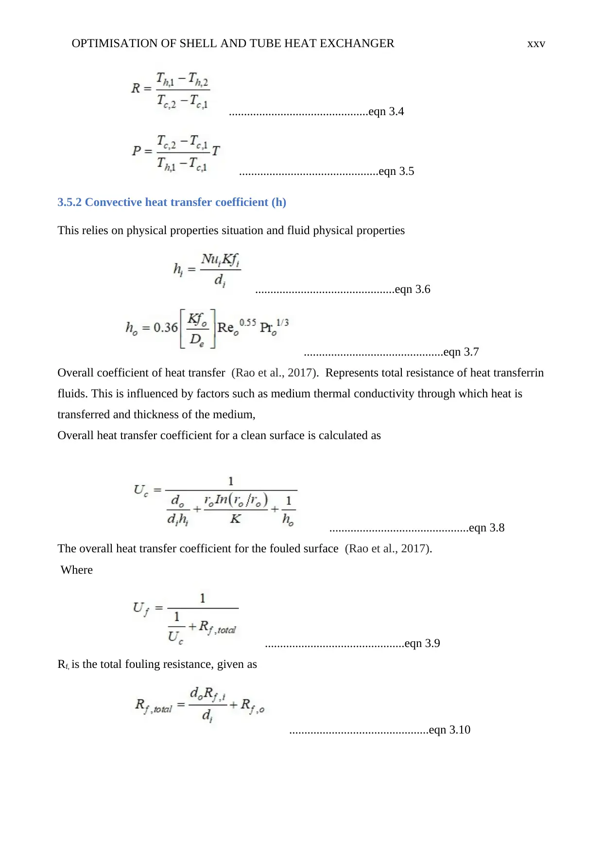
For crossflow exchangers with multi-pass, then LMTD is to be corrected by factor of correction (F).
This is dimensionless parameter that depends on high-temperature effectiveness P, rate of heat
capacity ratio and the arrangement of flow.
Where:
OPTIMISATION OF SHELL AND TUBE HEAT EXCHANGER xxv
..............................................eqn 3.4
..............................................eqn 3.5
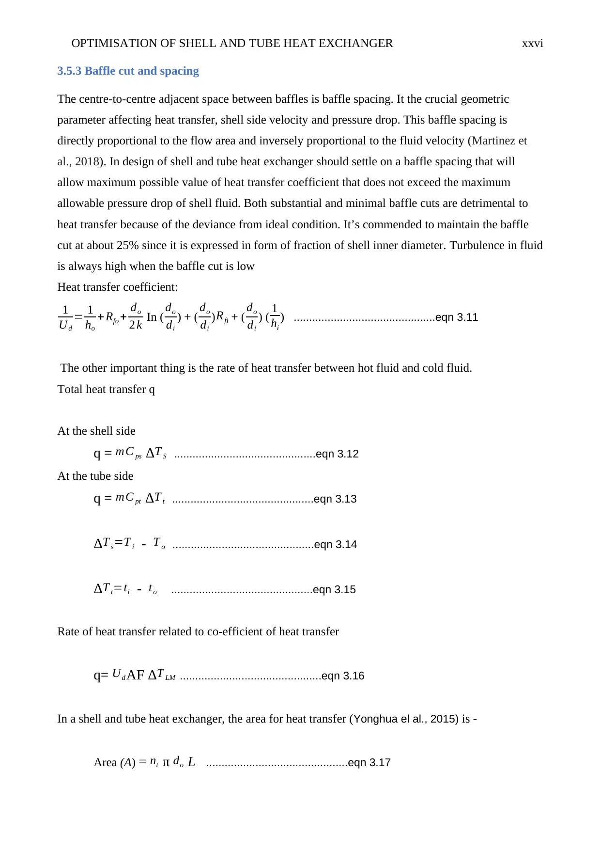
3.5.2 Convective heat transfer coefficient (h)
This relies on physical properties situation and fluid physical properties
..............................................eqn 3.6
..............................................eqn 3.7
Overall coefficient of heat transfer (Rao et al., 2017). Represents total resistance of heat transferrin
fluids. This is influenced by factors such as medium thermal conductivity through which heat is
transferred and thickness of the medium,
Overall heat transfer coefficient for a clean surface is calculated as
..............................................eqn 3.8
The overall heat transfer coefficient for the fouled surface (Rao et al., 2017).
Where
..............................................eqn 3.9
Rf, is the total fouling resistance, given as
..............................................eqn 3.10
Paraphrase This Document
Need a fresh take? Get an instant paraphrase of this document with our AI Paraphraser
OPTIMISATION OF SHELL AND TUBE HEAT EXCHANGER xxvi
3.5.3 Baffle cut and spacing
The centre-to-centre adjacent space between baffles is baffle spacing. It the crucial geometric
parameter affecting heat transfer, shell side velocity and pressure drop. This baffle spacing is
directly proportional to the flow area and inversely proportional to the fluid velocity (Martinez et
al., 2018). In design of shell and tube heat exchanger should settle on a baffle spacing that will
allow maximum possible value of heat transfer coefficient that does not exceed the maximum
allowable pressure drop of shell fluid. Both substantial and minimal baffle cuts are detrimental to
heat transfer because of the deviance from ideal condition. It’s commended to maintain the baffle
cut at about 25% since it is expressed in form of fraction of shell inner diameter. Turbulence in fluid
is always high when the baffle cut is low
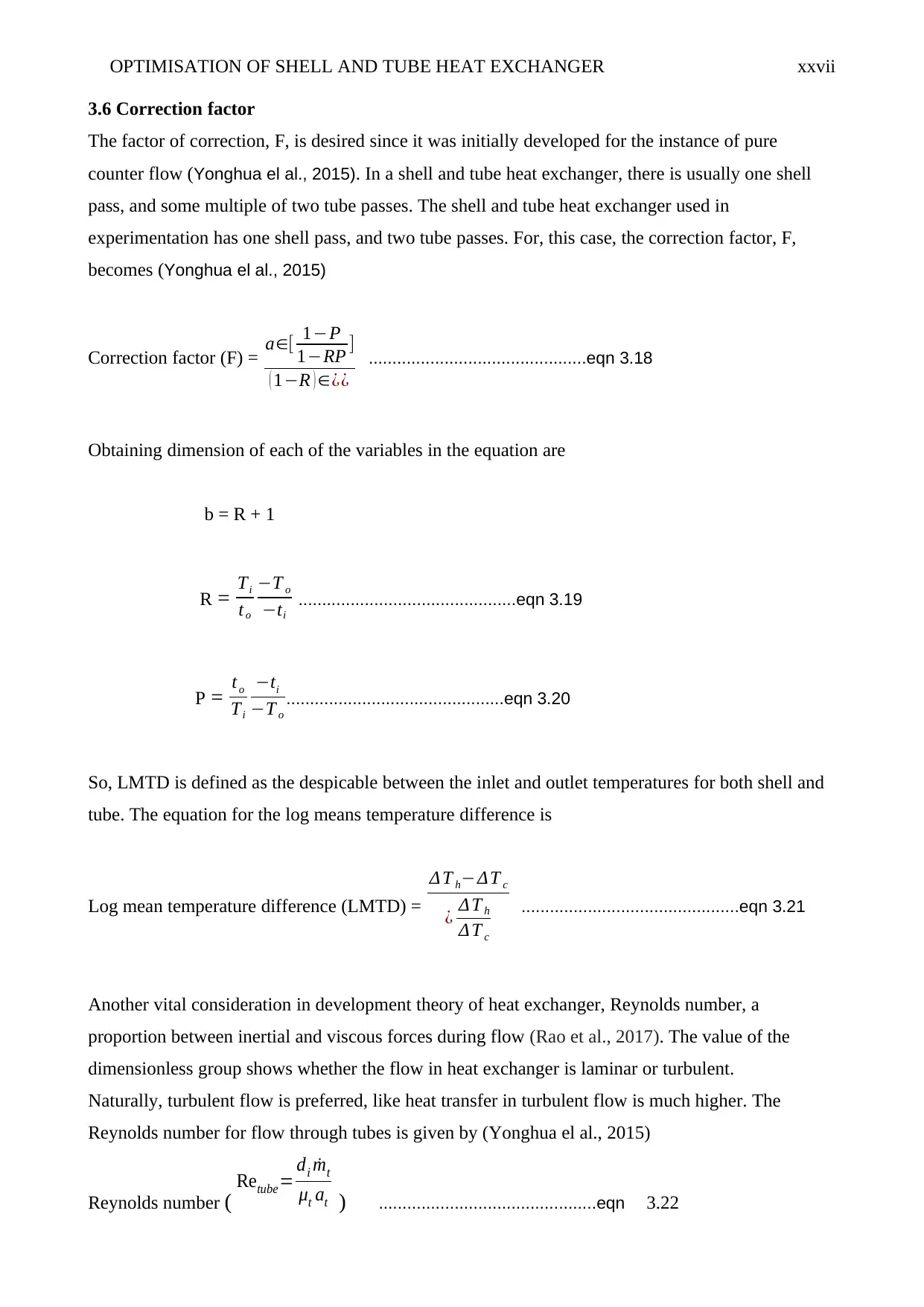
Heat transfer coefficient:
1
Ud
= 1
ho
+ Rfo + do
2 k In ( do
di
) + ( do
di
)Rfi + ( do
di
) ( 1
hi
) ..............................................eqn 3.11
The other important thing is the rate of heat transfer between hot fluid and cold fluid.
Total heat transfer q
At the shell side
q = mC ps ΔT S ..............................................eqn 3.12
At the tube side
q = mC pt ΔT t ..............................................eqn 3.13
ΔT s=T i - T o ..............................................eqn 3.14
ΔT t=ti - to ..............................................eqn 3.15
Rate of heat transfer related to co-efficient of heat transfer
q= Ud AF ΔT LM ..............................................eqn 3.16
In a shell and tube heat exchanger, the area for heat transfer (Yonghua el al., 2015) is -
Area (A) = nt π do L ..............................................eqn 3.17
OPTIMISATION OF SHELL AND TUBE HEAT EXCHANGER xxvii
3.6 Correction factor
The factor of correction, F, is desired since it was initially developed for the instance of pure
counter flow (Yonghua el al., 2015). In a shell and tube heat exchanger, there is usually one shell
pass, and some multiple of two tube passes. The shell and tube heat exchanger used in
experimentation has one shell pass, and two tube passes. For, this case, the correction factor, F,
becomes (Yonghua el al., 2015)
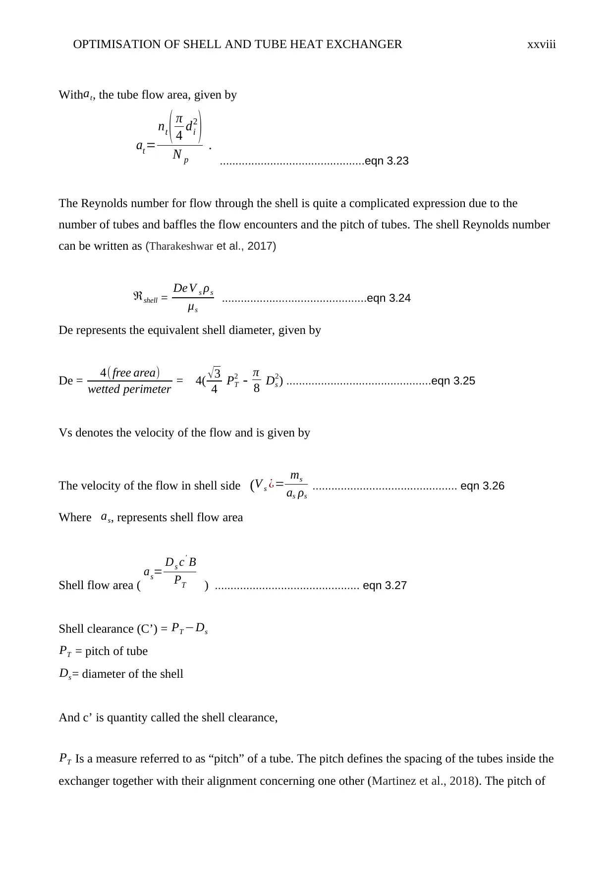
Correction factor (F) = a∈[ 1−P
1−RP ]
( 1−R ) ∈¿¿
..............................................eqn 3.18
Obtaining dimension of each of the variables in the equation are
b = R + 1
R = Ti
to
−T o
−ti
..............................................eqn 3.19
P = to
Ti
−ti
−T o
..............................................eqn 3.20
So, LMTD is defined as the despicable between the inlet and outlet temperatures for both shell and
tube. The equation for the log means temperature difference is
Log mean temperature difference (LMTD) =
Δ T h−ΔT c
¿ Δ T h
Δ T c
..............................................eqn 3.21
Another vital consideration in development theory of heat exchanger, Reynolds number, a
proportion between inertial and viscous forces during flow (Rao et al., 2017). The value of the
dimensionless group shows whether the flow in heat exchanger is laminar or turbulent.
Naturally, turbulent flow is preferred, like heat transfer in turbulent flow is much higher. The
Reynolds number for flow through tubes is given by (Yonghua el al., 2015)
Reynolds number ( Retube= di ˙mt
μt at ) ..............................................eqn 3.22
OPTIMISATION OF SHELL AND TUBE HEAT EXCHANGER xxviii
Withat, the tube flow area, given by
at=
nt ( π
4 di
2
)
N p
.
..............................................eqn 3.23
The Reynolds number for flow through the shell is quite a complicated expression due to the
number of tubes and baffles the flow encounters and the pitch of tubes. The shell Reynolds number
can be written as (Tharakeshwar et al., 2017)
ℜshell = DeV s ρs
μs
..............................................eqn 3.24
De represents the equivalent shell diameter, given by
De = 4( free area)
wetted perimeter = 4( √3
4 PT
2 - π
8 Ds
2) ..............................................eqn 3.25
Vs denotes the velocity of the flow and is given by
The velocity of the flow in shell side (V s ¿= ms
as ρs
.............................................. eqn 3.26
Where as, represents shell flow area
Shell flow area (
as= Ds c' B
PT ) .............................................. eqn 3.27
Shell clearance (C’) = PT −Ds
PT = pitch of tube
Ds= diameter of the shell
And c’ is quantity called the shell clearance,
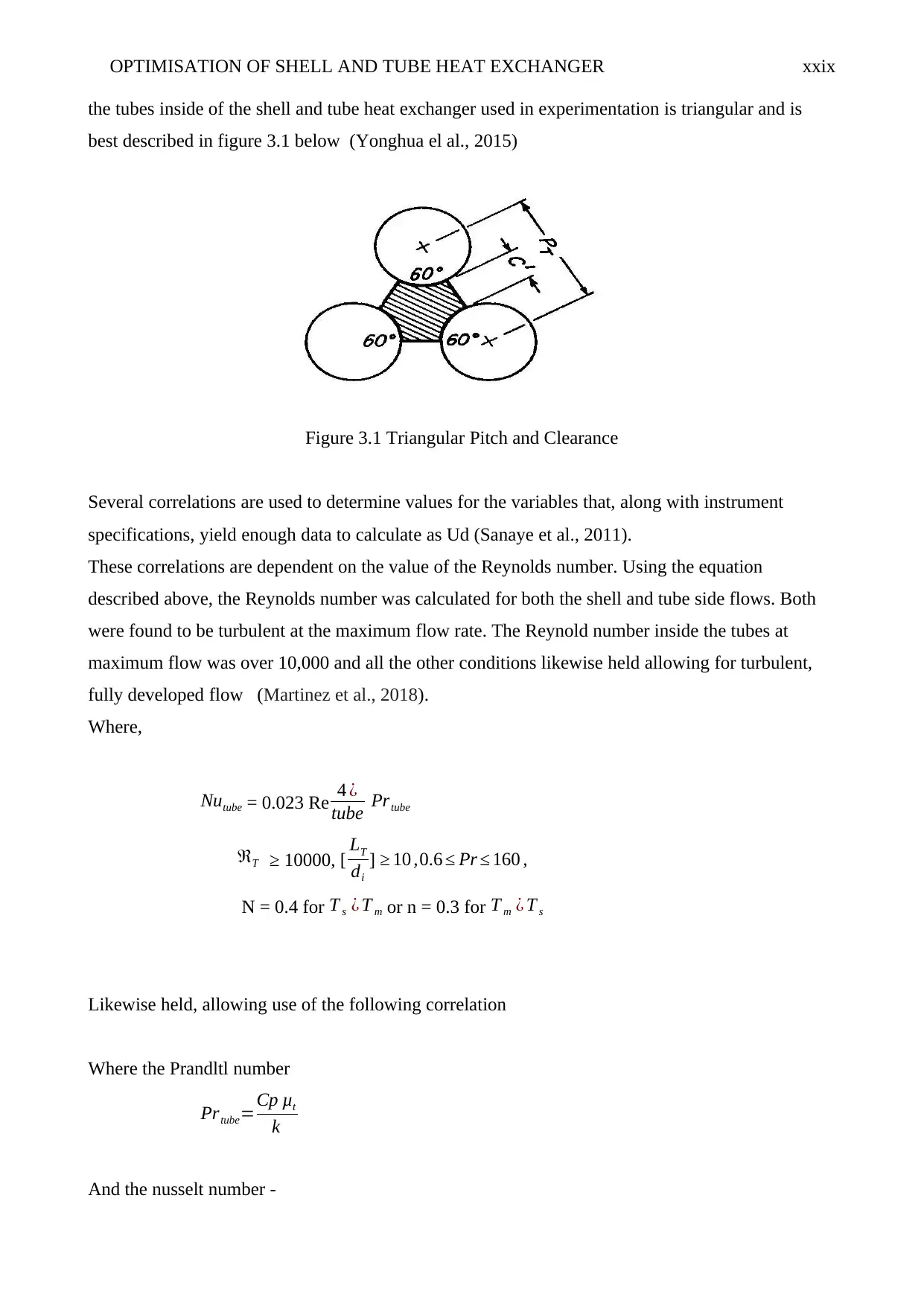
PT Is a measure referred to as “pitch” of a tube. The pitch defines the spacing of the tubes inside the
exchanger together with their alignment concerning one other (Martinez et al., 2018). The pitch of
Secure Best Marks with AI Grader
Need help grading? Try our AI Grader for instant feedback on your assignments.
OPTIMISATION OF SHELL AND TUBE HEAT EXCHANGER xxix
the tubes inside of the shell and tube heat exchanger used in experimentation is triangular and is
best described in figure 3.1 below (Yonghua el al., 2015)
Figure 3.1 Triangular Pitch and Clearance
Several correlations are used to determine values for the variables that, along with instrument
specifications, yield enough data to calculate as Ud (Sanaye et al., 2011).
These correlations are dependent on the value of the Reynolds number. Using the equation
described above, the Reynolds number was calculated for both the shell and tube side flows. Both
were found to be turbulent at the maximum flow rate. The Reynold number inside the tubes at
maximum flow was over 10,000 and all the other conditions likewise held allowing for turbulent,
fully developed flow (Martinez et al., 2018).
Where,
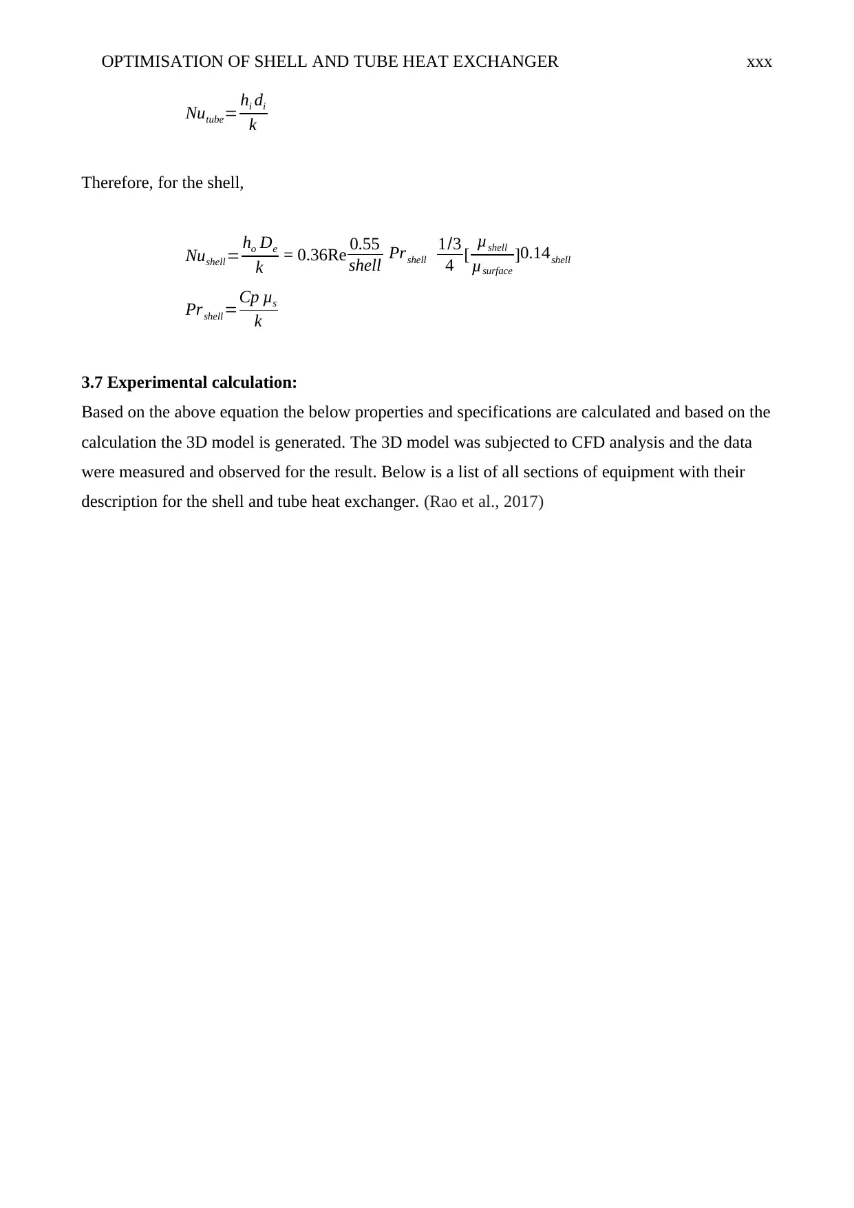
Nutube = 0.023 Re 4 ¿
tube Prtube
ℜT ≥ 10000, [ LT
di
] ≥ 10 ,0.6 ≤ Pr ≤ 160 ,
N = 0.4 for T s ¿ T m or n = 0.3 for T m ¿ T s
Likewise held, allowing use of the following correlation
Where the Prandltl number
Prtube=Cp μt
k
And the nusselt number -
OPTIMISATION OF SHELL AND TUBE HEAT EXCHANGER xxx
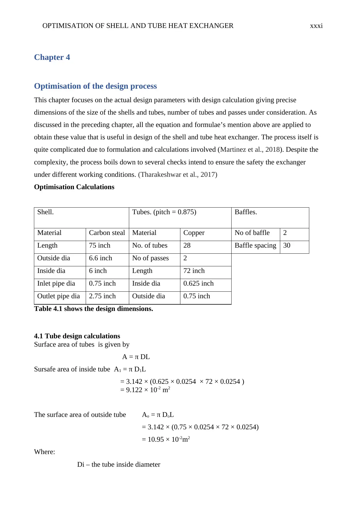
Nutube= hi di
k
Therefore, for the shell,
Nushell= ho De
k = 0.36Re 0.55
shell Prshell
1/3
4 [ μshell
μsurface
]0.14shell
Prshell=Cp μs
k
3.7 Experimental calculation:
Based on the above equation the below properties and specifications are calculated and based on the
calculation the 3D model is generated. The 3D model was subjected to CFD analysis and the data
were measured and observed for the result. Below is a list of all sections of equipment with their
description for the shell and tube heat exchanger. (Rao et al., 2017)
OPTIMISATION OF SHELL AND TUBE HEAT EXCHANGER xxxi
Chapter 4
Optimisation of the design process
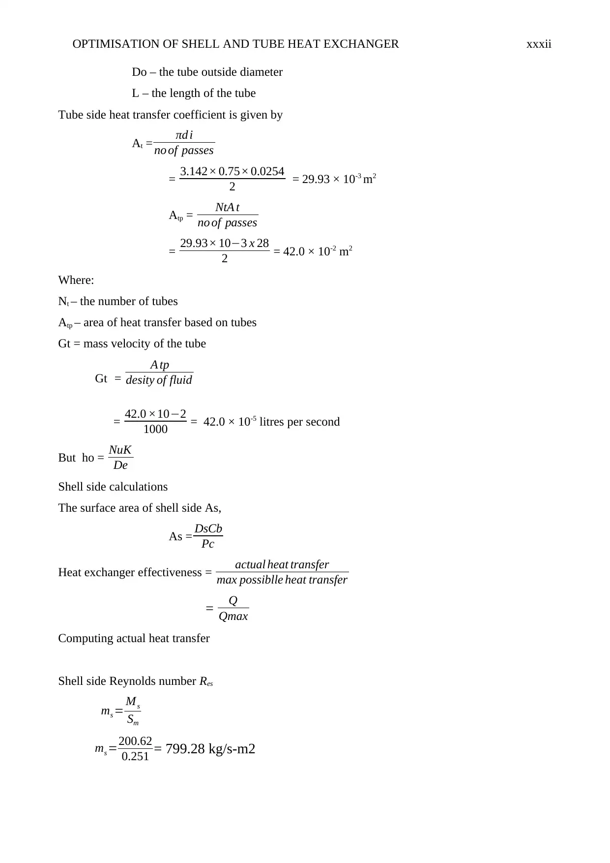
This chapter focuses on the actual design parameters with design calculation giving precise
dimensions of the size of the shells and tubes, number of tubes and passes under consideration. As
discussed in the preceding chapter, all the equation and formulae’s mention above are applied to
obtain these value that is useful in design of the shell and tube heat exchanger. The process itself is
quite complicated due to formulation and calculations involved (Martinez et al., 2018). Despite the
complexity, the process boils down to several checks intend to ensure the safety the exchanger
under different working conditions. (Tharakeshwar et al., 2017)
Optimisation Calculations
Shell. Tubes. (pitch = 0.875) Baffles.
Material Carbon steal Material Copper No of baffle 2
Length 75 inch No. of tubes 28 Baffle spacing 30
Outside dia 6.6 inch No of passes 2
Inside dia 6 inch Length 72 inch
Inlet pipe dia 0.75 inch Inside dia 0.625 inch
Outlet pipe dia 2.75 inch Outside dia 0.75 inch
Table 4.1 shows the design dimensions.
4.1 Tube design calculations
Surface area of tubes is given by
A = π DL
Sursafe area of inside tube A1 = π D1L
= 3.142 × (0.625 × 0.0254 × 72 × 0.0254 )
= 9.122 × 10⁻² m2
The surface area of outside tube Ao = π DoL
= 3.142 × (0.75 × 0.0254 × 72 × 0.0254)
= 10.95 × 10⁻²m2
Where:
Di – the tube inside diameter
Paraphrase This Document
Need a fresh take? Get an instant paraphrase of this document with our AI Paraphraser
OPTIMISATION OF SHELL AND TUBE HEAT EXCHANGER xxxii
Do – the tube outside diameter
L – the length of the tube
Tube side heat transfer coefficient is given by
At = πd i
no of passes
= 3.142× 0.75× 0.0254
2 = 29.93 × 10⁻³ m2
Atp = NtA t
no of passes
= 29.93× 10−3 x 28
2 = 42.0 × 10⁻² m2
Where:
Nt – the number of tubes
Atp – area of heat transfer based on tubes
Gt = mass velocity of the tube
Gt =
A tp
desity of fluid
= 42.0 ×10⁻²
1000 = 42.0 × 10⁻⁵ litres per second
But ho = NuK
De
Shell side calculations
The surface area of shell side As,
As = DsCb
Pc
Heat exchanger effectiveness = actual heat transfer
max possiblle heat transfer
= Q
Qmax
Computing actual heat transfer
Shell side Reynolds number Res
ms = Ms
Sm
ms =200.62
0.251 = 799.28 kg/s-m2
OPTIMISATION OF SHELL AND TUBE HEAT EXCHANGER xxxiii
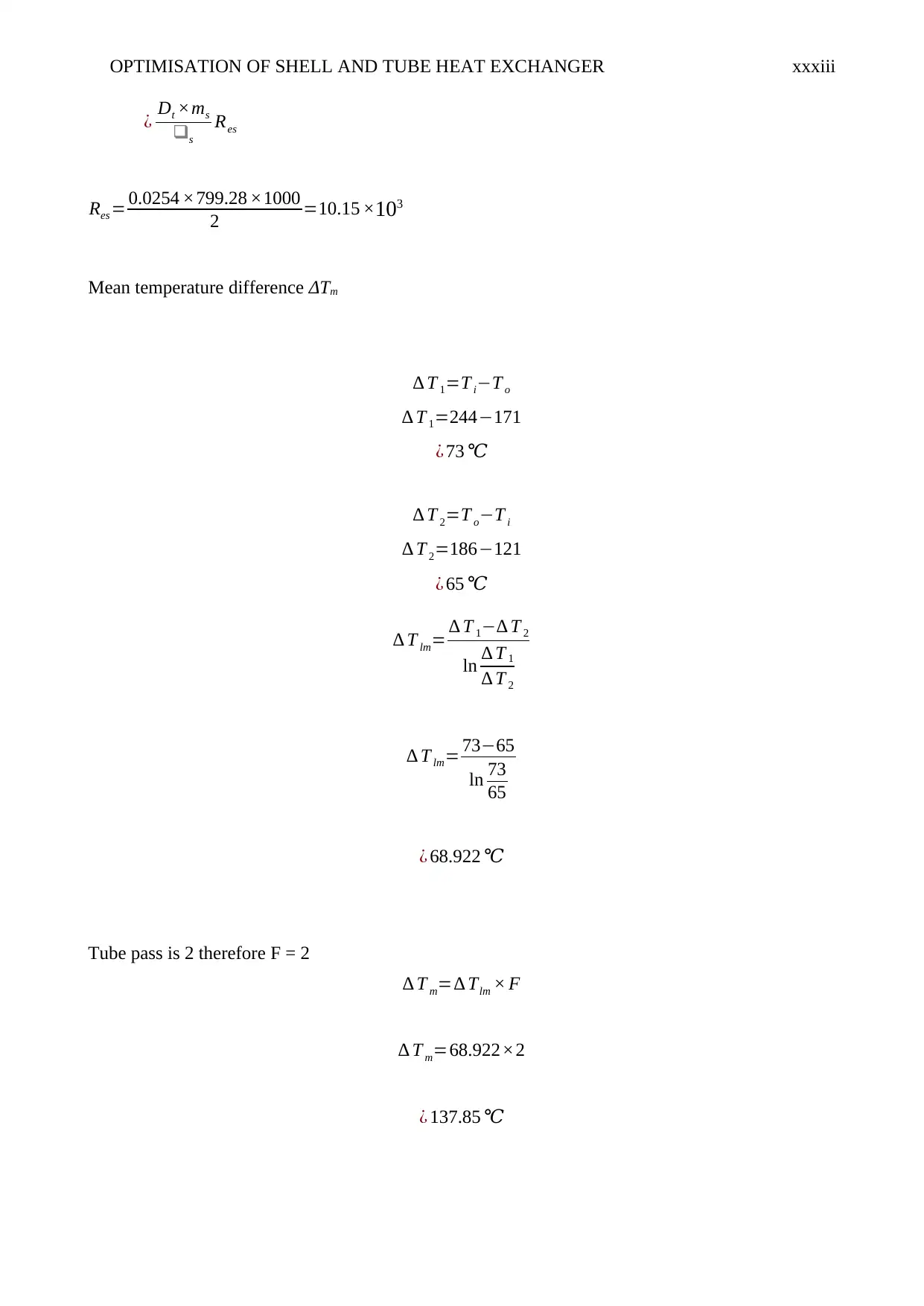
¿ Dt ×ms
❑s
Res
Res = 0.0254 ×799.28 ×1000
2 =10.15 ×10³
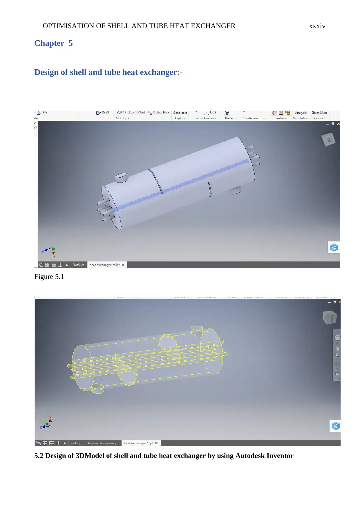
Mean temperature difference ΔTm
∆ T 1=T i−T o
∆ T 1=244−171
¿ 73 ℃
∆ T 2=T o−T i
∆ T 2=186−121
¿ 65 ℃
∆ T lm= ∆ T 1−∆ T 2
ln ∆ T 1
∆ T 2
∆ T lm= 73−65
ln 73
65
¿ 68.922 ℃
Tube pass is 2 therefore F = 2
∆ T m=∆ Tlm × F
∆ T m=68.922×2
¿ 137.85 ℃
OPTIMISATION OF SHELL AND TUBE HEAT EXCHANGER xxxiv
Chapter 5
Design of shell and tube heat exchanger:-
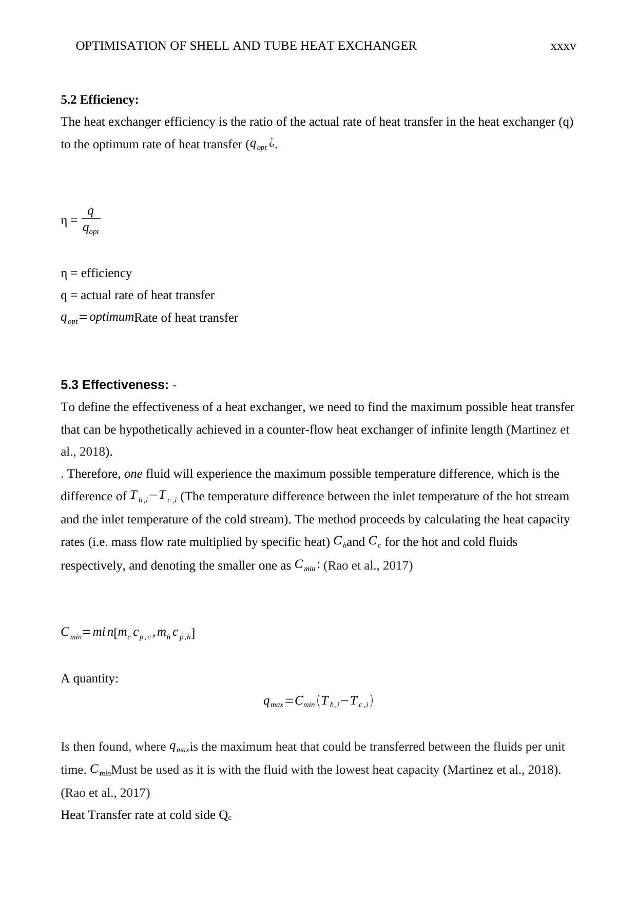
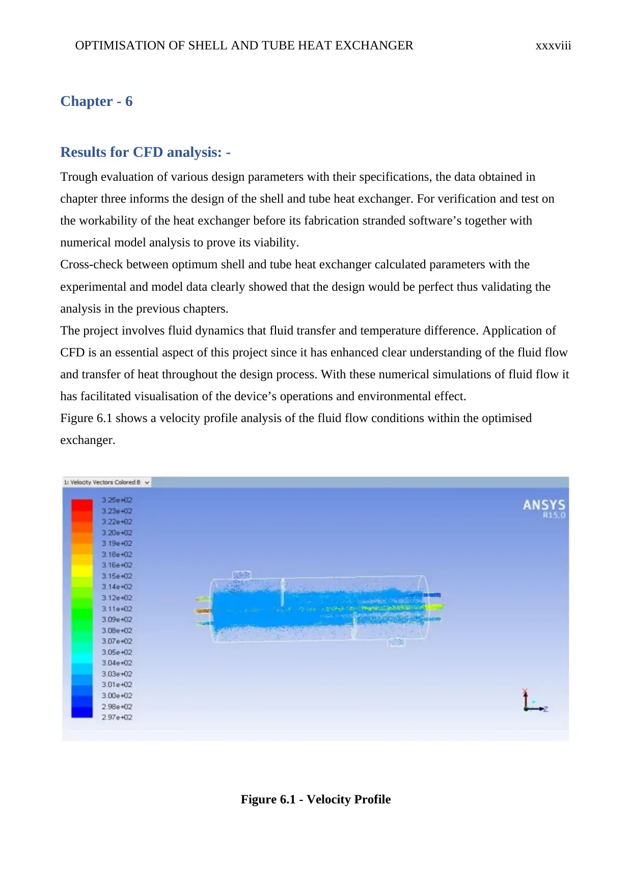
Figure 5.1
5.2 Design of 3DModel of shell and tube heat exchanger by using Autodesk Inventor
Chapter 5
Design of shell and tube heat exchanger:-
Figure 5.1
5.2 Design of 3DModel of shell and tube heat exchanger by using Autodesk Inventor
Secure Best Marks with AI Grader
Need help grading? Try our AI Grader for instant feedback on your assignments.
OPTIMISATION OF SHELL AND TUBE HEAT EXCHANGER xxxv
5.2 Efficiency:
The heat exchanger efficiency is the ratio of the actual rate of heat transfer in the heat exchanger (q)
to the optimum rate of heat transfer ( qopt ¿.
η = q
qopt
η = efficiency
q = actual rate of heat transfer
qopt=optimumRate of heat transfer
5.3 Effectiveness: -
To define the effectiveness of a heat exchanger, we need to find the maximum possible heat transfer
that can be hypothetically achieved in a counter-flow heat exchanger of infinite length (Martinez et
al., 2018).
. Therefore, one fluid will experience the maximum possible temperature difference, which is the
difference of T h ,i−T c ,i (The temperature difference between the inlet temperature of the hot stream
and the inlet temperature of the cold stream). The method proceeds by calculating the heat capacity
rates (i.e. mass flow rate multiplied by specific heat) Chand Cc for the hot and cold fluids
respectively, and denoting the smaller one as Cmin : (Rao et al., 2017)
Cmin=mi n[mc cp , c , mh c p ,h]
A quantity:
qmax =Cmin (T h ,i−T c ,i )
Is then found, where qmaxis the maximum heat that could be transferred between the fluids per unit
time. CminMust be used as it is with the fluid with the lowest heat capacity (Martinez et al., 2018).
(Rao et al., 2017)
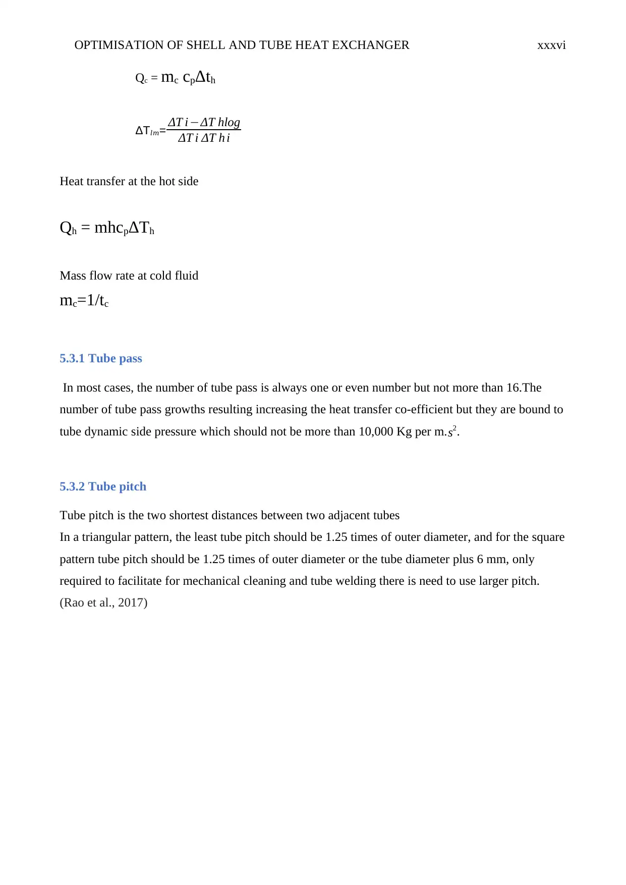
Heat Transfer rate at cold side Qc
OPTIMISATION OF SHELL AND TUBE HEAT EXCHANGER xxxvi
Qc = mc cpΔth
ΔT𝑙𝑚= ΔT i−ΔT hlog
ΔT i ΔT h i
Heat transfer at the hot side
Qh = mhcpΔTh
Mass flow rate at cold fluid
mc=1/tc
5.3.1 Tube pass
In most cases, the number of tube pass is always one or even number but not more than 16.The
number of tube pass growths resulting increasing the heat transfer co-efficient but they are bound to
tube dynamic side pressure which should not be more than 10,000 Kg per m.s2.
5.3.2 Tube pitch
Tube pitch is the two shortest distances between two adjacent tubes
In a triangular pattern, the least tube pitch should be 1.25 times of outer diameter, and for the square
pattern tube pitch should be 1.25 times of outer diameter or the tube diameter plus 6 mm, only
required to facilitate for mechanical cleaning and tube welding there is need to use larger pitch.
(Rao et al., 2017)

OPTIMISATION OF SHELL AND TUBE HEAT EXCHANGER xxxvii
Paraphrase This Document
Need a fresh take? Get an instant paraphrase of this document with our AI Paraphraser
OPTIMISATION OF SHELL AND TUBE HEAT EXCHANGER xxxviii
Chapter - 6
Results for CFD analysis: -
Trough evaluation of various design parameters with their specifications, the data obtained in
chapter three informs the design of the shell and tube heat exchanger. For verification and test on
the workability of the heat exchanger before its fabrication stranded software’s together with
numerical model analysis to prove its viability.
Cross-check between optimum shell and tube heat exchanger calculated parameters with the
experimental and model data clearly showed that the design would be perfect thus validating the
analysis in the previous chapters.
The project involves fluid dynamics that fluid transfer and temperature difference. Application of
CFD is an essential aspect of this project since it has enhanced clear understanding of the fluid flow
and transfer of heat throughout the design process. With these numerical simulations of fluid flow it
has facilitated visualisation of the device’s operations and environmental effect.
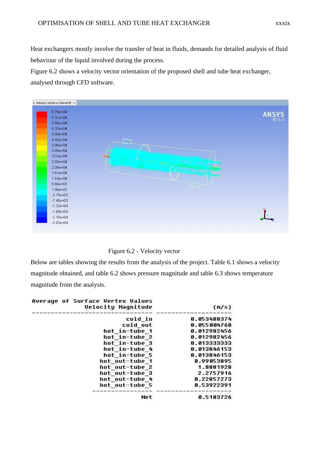
Figure 6.1 shows a velocity profile analysis of the fluid flow conditions within the optimised
exchanger.
Figure 6.1 - Velocity Profile
OPTIMISATION OF SHELL AND TUBE HEAT EXCHANGER xxxix
Heat exchangers mostly involve the transfer of heat in fluids, demands for detailed analysis of fluid
behaviour of the liquid involved during the process.
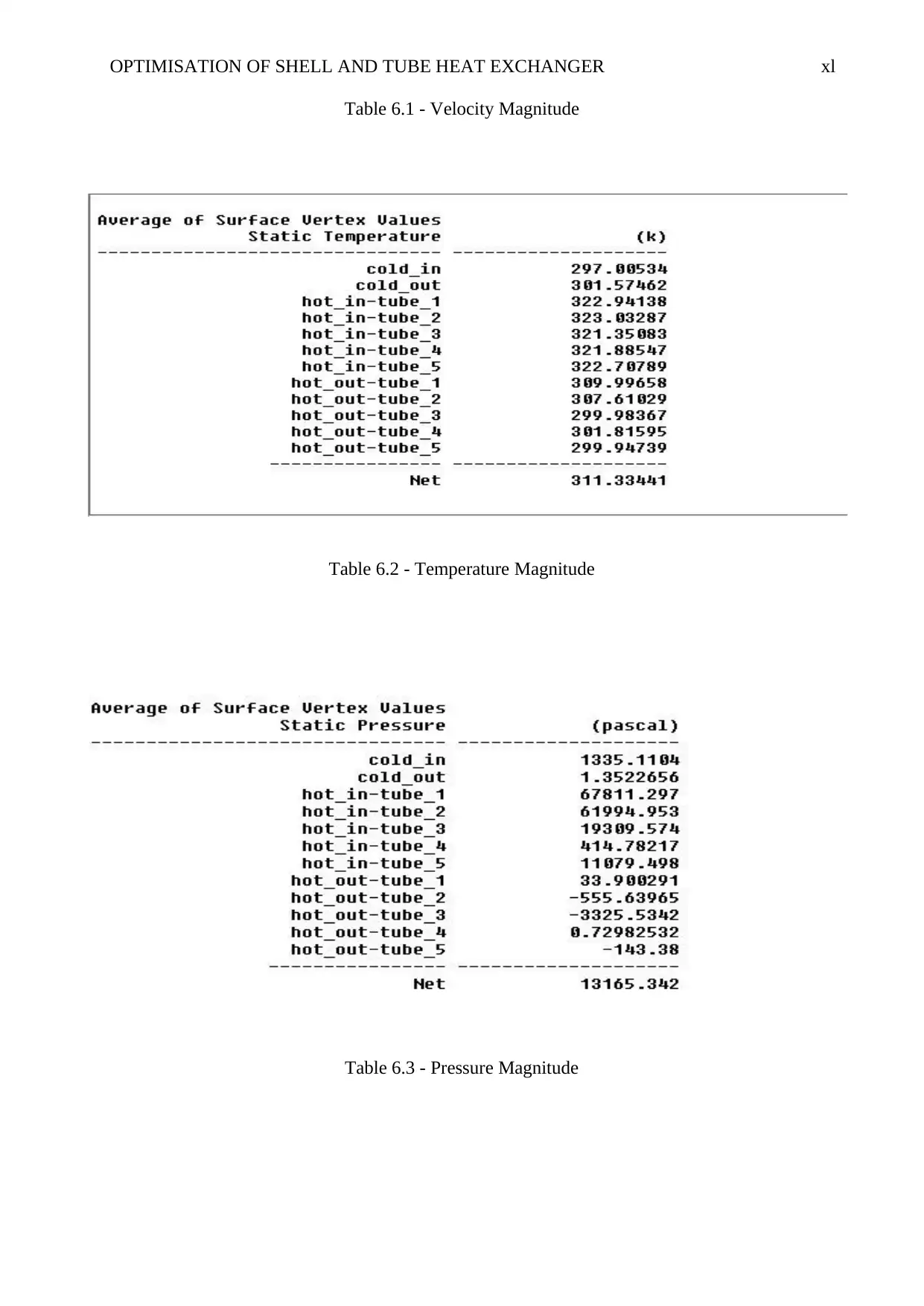
Figure 6.2 shows a velocity vector orientation of the proposed shell and tube heat exchanger,
analysed through CFD software.
Figure 6.2 - Velocity vector
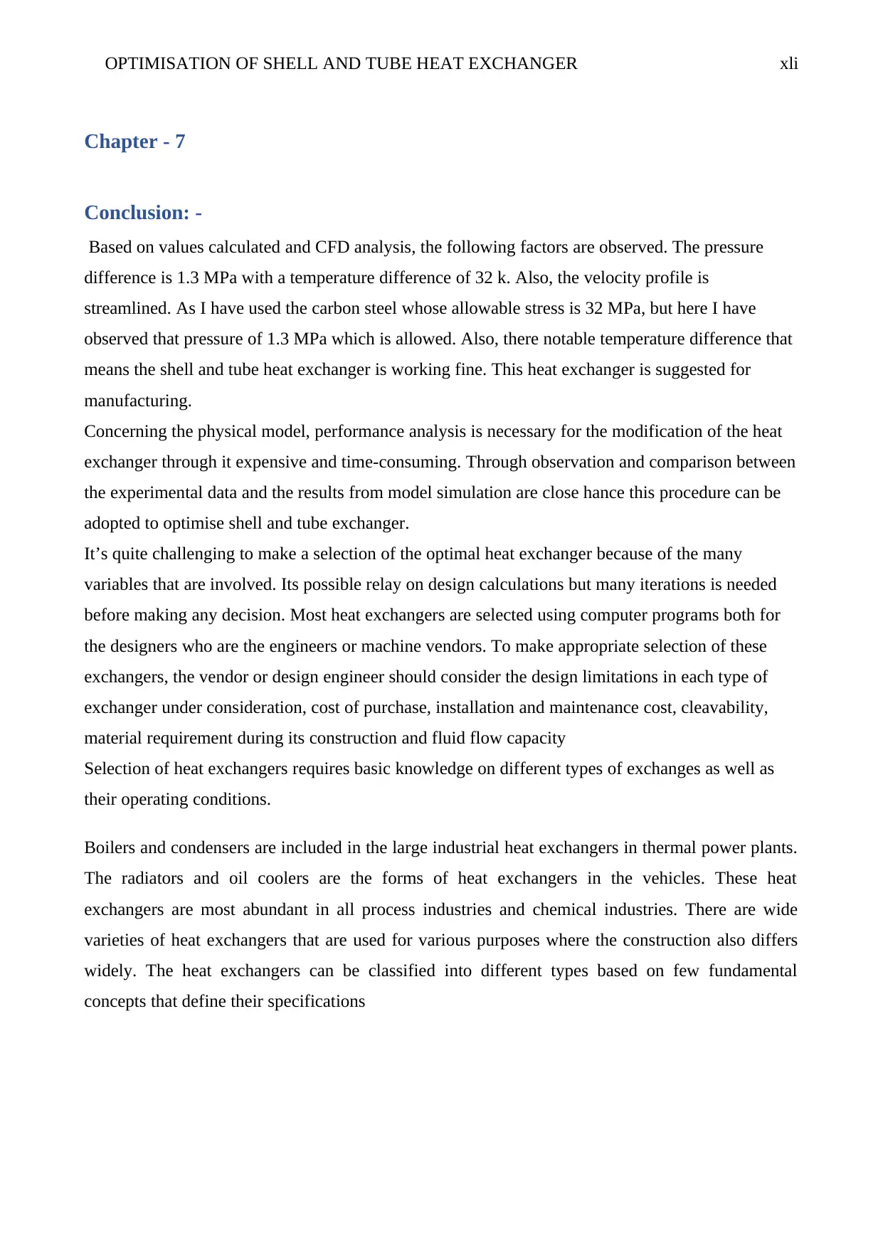
Below are tables showing the results from the analysis of the project. Table 6.1 shows a velocity
magnitude obtained, and table 6.2 shows pressure magnitude and table 6.3 shows temperature
magnitude from the analysis.
OPTIMISATION OF SHELL AND TUBE HEAT EXCHANGER xl
Table 6.1 - Velocity Magnitude
Table 6.2 - Temperature Magnitude
Table 6.3 - Pressure Magnitude
Table 6.1 - Velocity Magnitude
Table 6.2 - Temperature Magnitude
Table 6.3 - Pressure Magnitude
Secure Best Marks with AI Grader
Need help grading? Try our AI Grader for instant feedback on your assignments.
OPTIMISATION OF SHELL AND TUBE HEAT EXCHANGER xli
Chapter - 7
Conclusion: -
Based on values calculated and CFD analysis, the following factors are observed. The pressure
difference is 1.3 MPa with a temperature difference of 32 k. Also, the velocity profile is
streamlined. As I have used the carbon steel whose allowable stress is 32 MPa, but here I have
observed that pressure of 1.3 MPa which is allowed. Also, there notable temperature difference that
means the shell and tube heat exchanger is working fine. This heat exchanger is suggested for
manufacturing.
Concerning the physical model, performance analysis is necessary for the modification of the heat
exchanger through it expensive and time-consuming. Through observation and comparison between
the experimental data and the results from model simulation are close hance this procedure can be
adopted to optimise shell and tube exchanger.
It’s quite challenging to make a selection of the optimal heat exchanger because of the many
variables that are involved. Its possible relay on design calculations but many iterations is needed
before making any decision. Most heat exchangers are selected using computer programs both for
the designers who are the engineers or machine vendors. To make appropriate selection of these
exchangers, the vendor or design engineer should consider the design limitations in each type of
exchanger under consideration, cost of purchase, installation and maintenance cost, cleavability,
material requirement during its construction and fluid flow capacity
Selection of heat exchangers requires basic knowledge on different types of exchanges as well as
their operating conditions.
Boilers and condensers are included in the large industrial heat exchangers in thermal power plants.
The radiators and oil coolers are the forms of heat exchangers in the vehicles. These heat
exchangers are most abundant in all process industries and chemical industries. There are wide
varieties of heat exchangers that are used for various purposes where the construction also differs
widely. The heat exchangers can be classified into different types based on few fundamental
concepts that define their specifications
OPTIMISATION OF SHELL AND TUBE HEAT EXCHANGER xlii
Chapter - 8
Recommendations for future work: -
For CFD analysis, I have used Carbon steel material for shell and copper material for tubes. In
further studies I recommend to and use different materials such as stainless steel, carbon Nanotube
material and alloys for CFD analysis and will compare the output results to describe which material
properties are better to get high heat transfer rate. Not only this, I will consider fluid properties in
further studies by using high-density fluid such as corrosive fluid, cooling water, less viscous fluid,
high-pressure steam and hotter fluid which helps in maintaining the required heat standard.
OPTIMISATION OF SHELL AND TUBE HEAT EXCHANGER xliii
Chapter – 9
Reference:
B. Gay, N. V. MackleyAnd J. D. Jenkins, “Shell-Side Heat Transfer In Baffled Cylindrical Shell-
And Tube Exchangers-An Electrochemical Mass-Transfer Modelling Technique,” Ht. J. Heat Mass
Transfer.19 (1976) 995-1002
Bevevino, J.W., et. Al., “Standards Of Tubular Exchanger Manufacturing Association,” TEMA,
New York, 6th Edition, (1988)
Chris Haslego, Design considerations for shell and tube heat exchanger (2010)
Coulson &Richardson’s, “Chemical Engineering Design,” Elsevier Butterworth-Heinemann, Vol. 6,
No 4,(2005), pp 634-724
E.Edwards, J., Design and Rating Shell and Tube Heat Exchanger (2008)
H. Lia, V. Kottke, “Analysis of Local Shell side Heat and Mass Transfer in the Shell and Tube
Heat Exchanger with Disc and Doughnut Baffles,” International Journal of Heat and Mass Transfer
42 (1999) 3509-3521
http://www.htri.net/articles/htri_xchanger_suite
KERN, D.Q., “Process Heat Transfer, “McGraw-Hill, Inc., New York,(1950)
Kern, Process Heat Transfer, pp. 137, 139, Figure (1990)
M. Fesanghary ,E. Damangir , I. Soleimani, “Design Optimization Of Shell And Tube Heat
Exchangers Using Global Sensitivity Analysis And Harmony Search Algorithm,” Applied Thermal
Engineering 29 (2009) 1026–1031
Martinez, L. C., Mariani, V. C., Coelho, L. S., & Segundo, E. H. V. (2018). DIFFERENTIAL
EVOLUTION ALGORITHM APPLIED IN A NUMERICAL COST OPTIMIZATION DESIGN
OF A SHELL AND-TUBE HEAT EXCHANGER. RETERM-Thermal Engineering, 16(1), 11-18.
Mirzaei, M., Hajabdollahi, H., & Fadakar, H. (2017). Multi-objective optimization of shell-and-tube
heat exchanger by constructal theory. Applied Thermal Engineering, 125, 9-19.
Mohanty, D. K. (2016). Application of firefly algorithm for design optimization of a shell and tube
heat exchanger from economic point of view. International Journal of Thermal Sciences, 102, 228-
238.
Mukherjee R., chemical engineering progress (1998)
Mukherjee.R.,”Effectively Design Shell-And-Tube Heat Exchangers, “Chemical Engineering
Progress, February(1998), pp 21-37
Paraphrase This Document
Need a fresh take? Get an instant paraphrase of this document with our AI Paraphraser
OPTIMISATION OF SHELL AND TUBE HEAT EXCHANGER xliv
N. Xie, Q.W. Wang , M. Zeng, L.Q. Luo, “Heat Transfer Analysis For Shell-And-Tube Heat
Exchangers with Experimental Data By Artificial Neural Networks Approach,” Applied Thermal
Engineering 27 (2007) 1096–1104
Naphon, “Thermal Performance And Pressure Drop Of The Helical-Coil Heat Exchangers With
And Without Helically Crimped Fins,” International Communications In Heat And Mass Transfer
34 (2007) 321–330
Poddar, T.K. And Polley, G.T., Optimize Shell-And-Tube Heat Exchangers Design, Chemical
Engineering Progress, September(2000),pp 41- 46
Raja, B. D., Jhala, R. L., & Patel, V. (2017). Many-objective optimization of shell and tube heat
exchanger. Thermal science and Engineering progress, 2, 87-101.
Rao, R. V., & Saroj, A. (2017). Constrained economic optimization of shell-and-tube heat
exchangers using elitist-Jaya algorithm. Energy, 128, 785-800.
Rao, R. V., & Saroj, A. (2017). Economic optimization of shell-and-tube heat exchanger using Jaya
algorithm with maintenance consideration. Applied Thermal Engineering, 116, 473-487.
Retrieved from – UFThermolabs
Sepehr Sanaye, Hassan Hajabdollahi, “Multi-Objective Optimization Of Shell And Tube Heat
Exchangers,” Applied Thermal Engineering 30 (2010), 1937-1945
Simin Wang, Jian Wen, Yanzhong Li, “An Experimental Investigation Of Heat Transfer
Enhancement A Shell-And-Tube Heat Exchanger,” Applied Thermal Engineering 29 (2009) 2433–
2438
Standards of the Tubular Exchange Manufacturers Association, 6th ed., Tubular Exchanger
Manufacturers Association, New York, 1978.
Sukhatme, S.P., “Heat Exchangers, A Text Book On Heat Transfer, “University Press India
Limited(1996), pp 201-226
TaborekJ.,Shell-And-Tube Heat Exchangers, Heat Exchanger Data Handbook, Hemisphere, (1983)
pp 3.3.1-3.311
Tharakeshwar, T. K., Seetharamu, K. N., & Prasad, B. D. (2017). Multi-objective optimization
using bat algorithm for shell and tube heat exchangers. Applied Thermal Engineering, 110, 1029-
1038.
V.K. Patel, R.V. Rao, “Design Optimization Of Shell-And-Tube Heat Exchanger Using Particle
Swarmoptimization Technique,” Applied Thermal Engineering 30 (2010) 1417-1425
Van Der Ploeg, H.J., And B.I. Masters, “A New Shell-And-Tube Option For Refineries,” Petroleum
Technology Quarterly, Vol 2, No 3, (Autumn 1997), pp 91-95.
Wen, J., Yang, H., Jian, G., Tong, X., Li, K., & Wang, S. (2016). Energy and cost optimization of
shell and tube heat exchanger with helical baffles using Kriging metamodel based on
OPTIMISATION OF SHELL AND TUBE HEAT EXCHANGER xlv
MOGA. International Journal of heat and Mass transfer, 98, 29-39.
Wilfried Roetzel, Deiying W. Lee, “Effect of Baffle/Shell Leakage Flowon Heat Transfer in Shell-
and-TubeHeat Exchangers,” Experimental Thermal and Fluid Science 8 (1994) 10-20
Yonghua You, Aiwu Fan, Suyi Huang, Wei Liu, “Numerical Modelling And Experimental
Validation Of Heat Transfer And Flow Resistance On The Shell Side Of A Shell-And-Tube Heat
Exchanger With Flower Baffles,” International Journal Of Heat And Mass Transfer 55 (2012)
7561–7569
1 out of 45
Related Documents
Your All-in-One AI-Powered Toolkit for Academic Success.
+13062052269
info@desklib.com
Available 24*7 on WhatsApp / Email
![[object Object]](/_next/static/media/star-bottom.7253800d.svg)
Unlock your academic potential
© 2024 | Zucol Services PVT LTD | All rights reserved.


