Production System Optimization: Cooking-Pots from Recycled Steel
VerifiedAdded on 2023/06/13
|10
|2391
|338
Report
AI Summary
This report details the optimization of a production system for manufacturing cooking pots, incorporating 25% recycled steel. The existing process layout is analyzed, highlighting issues such as high material handling costs and bottlenecks. The objective is to improve the layout design to maximize production throughput, eliminate bottlenecks, and optimize machine utilization while maintaining product quality. The proposed solution involves a purely analytical method focusing on cost and efficiency. Key improvements include rearranging departments to minimize operational costs, reduce material movement, and group similar departments to streamline production planning. The report presents a cost analysis, demonstrating potential cost savings from the proposed rearrangements. An activity cycle diagram illustrates the improved layout, designed for in-process recyclability. The conclusion emphasizes the importance of optimizing machine utilization and continuous improvement through real-time simulation techniques to further enhance the adopted analytical optimization approach.
OPTIMIZED PRODUCTION SYSTEM OF A MANUFACTURING
CONCERN PRODUCING COOKING-POTS FROM 25% RECYCLED
MATERIALS
PREPARED BY:
DATE: 30TH March 2018
CONCERN PRODUCING COOKING-POTS FROM 25% RECYCLED
MATERIALS
PREPARED BY:
DATE: 30TH March 2018
Paraphrase This Document
Need a fresh take? Get an instant paraphrase of this document with our AI Paraphraser
INTRODUCTION
Process layouts are the most common production system in various factory settings. It is
composed of departmental units where various manufacturing processes are undertaken to
convert the raw materials inventory and semi-finished into finished inventory. In this report, a
case example of a production system that manufactures cooking pots is proposed. The layout of
the system is illustrated in figure 1. Notably, common production challenges often occur in the
concern such as: considerably high cost of material handling and transfer; there exists
bottlenecks within the shop floor such that either machine becomes idle or semi-finished parts
are made to wait in a queue. Therefore, the objective of this report is to: present both the existing
layout and thereafter produce an improved layout design through a systematic optimization
process such that production throughput is maximized, the existing bottlenecks are eliminated
and machines are optimally utilized while ensuring quality of finished products is beyond
reproach. In this case, a purely analytical method is proposed to solve the layout problems. The
main criteria are cost and efficiency.
THE PROCESS LAYOUT
The illustration depicts the simplified layout of the factory in which cooking pots are
manufactured. From the layout, it can be noticed that there are about three phase units namely:
Raw material processing, actual production and quality inspection. These three units are arranged
side by side and demarcation is done using a solid wall and only through the regulated gate
openings can the material flow to the next phase. This is done both as a safety and a quality
control measure. It should be noted that the control and office rooms are not included in the
illustrated layout as only the focus is on the flow of raw material and semi-finished material
within the shop floor. The raw material processing unit undertakes preparation of the raw
material to the form and size required in the production unit. The quality inspection is integrated
within the process layout such that once production is finalized, only a few quality checks are
done.
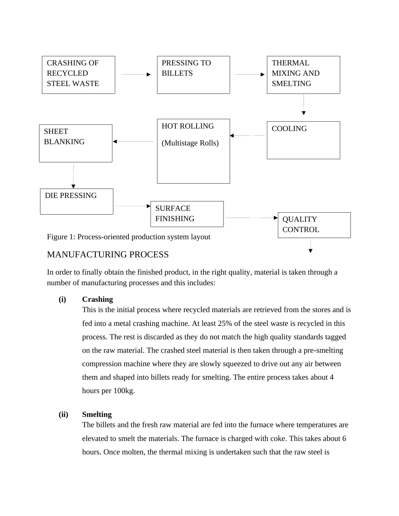
Figure 1: Process-oriented production system layout
MANUFACTURING PROCESS
In order to finally obtain the finished product, in the right quality, material is taken through a
number of manufacturing processes and this includes:
(i) Crashing
This is the initial process where recycled materials are retrieved from the stores and is
fed into a metal crashing machine. At least 25% of the steel waste is recycled in this
process. The rest is discarded as they do not match the high quality standards tagged
on the raw material. The crashed steel material is then taken through a pre-smelting
compression machine where they are slowly squeezed to drive out any air between
them and shaped into billets ready for smelting. The entire process takes about 4
hours per 100kg.
(ii) Smelting
The billets and the fresh raw material are fed into the furnace where temperatures are
elevated to smelt the materials. The furnace is charged with coke. This takes about 6
hours. Once molten, the thermal mixing is undertaken such that the raw steel is
CRASHING OF
RECYCLED
STEEL WASTE
THERMAL
MIXING AND
SMELTING
PRESSING TO
BILLETS
COOLINGHOT ROLLING
(Multistage Rolls)
SHEET
BLANKING
DIE PRESSING
SURFACE
FINISHING QUALITY
CONTROL
⊘ This is a preview!⊘
Do you want full access?
Subscribe today to unlock all pages.

Trusted by 1+ million students worldwide
thoroughly mixed with the recycled steel in the ratio 4:1. At the end of the process,
the materials are fed into a multistage cooling where the high temperatures are
gradually reduced through a number of cooling phases facilitated by a mechanical
fan.
(iii) Cooling & Rolling
Once cooled, material is fed into a set of rolls via a conveyor. The rolling is done in a
gradual fashion such that the gap between rolls progressively reduces as the material
is passed through the rolls until the desired steel thickness is achieved. Lastly, the
resulting sheet is placed in buffer storage ready for the second and final phase of
production.
(iv) Blanking
In order to produce the required circular shape, the steel sheets are taken through a
blanking machine where circular sheets are obtained of different sizes based on the
daily production schedule. This takes about 2 hours for 500 pieces and they are
passed to the next process.
(v) Cold Die forging
The blanked steel sheets are fed into a vertical set of die such that the hummer slowly
squeezes it within a die (which mimics the shape of the cooking pot required). The
resulting product is the cooking pot.
(vi) Handle making
The handles are made of plastic through injection molding. They are hardened
afterwards. Normally plastic granules are fed into a screw feeder and it takes 3 hours
for the entire process to complete.
(vii) Handle Assembly
Meanwhile there is a work-in-process inventory for the cooking pots as the handles
are being made. Once done, assembly work is done where the handles are fixed on
the cooked pots. This is a manual process and a bottleneck per se.
(viii) Finishing and quality control
Paraphrase This Document
Need a fresh take? Get an instant paraphrase of this document with our AI Paraphraser
As mentioned earlier, the entire manufacturing is done in an environment that greatly
integrates the aspects of quality. In this case, the cooking pots are sampled to check
on the level of quality so far attained. Some of the quality features include: surface
finish, dimensional accuracy, sharp edges, general shape and thickness.
Normally light grinding, pre-polishing and polishing are done to perfect the product
quality level and aesthetics.
(ix) Packaging and shipment
This is the last stage where the finished cookware is safely packed, ready for
shipment to the market. The storage unit is just within the shop floor area to minimize
transportation costs.
IMPROVED PRODUCTION SYSTEM
The layout illustrated in figure 1 can be improved further as a number of layout problems have
been identified; such as existing bottlenecks at the assembly point as the cooking pots have to
wait in the queue for the handles to be finalized. Meanwhile, since it is a manual operation, there
is low production throughput at this juncture and such inefficiency costs the company some
dollars as will be realized.
Now, the approach being adopted to improve the production system such that the layout is
optimized is a cost criteria where departments can be rearranged in a fashion that minimizes
operational costs, maximizing profitability and improves overall production efficiency; by for
instance eliminating unnecessarily high number of material movement.
Suppose now we undertake the rearrangements such that the assembly department is matched
with the pressing department. This then reduces the bottleneck at the manual assembly point.
Planning department should be able to economize further the throughput from the press and
assembled parts so that minimum work-in-process can further be realized. In fact this will free up
the holding space by the buffers and costs savings can be utilized elsewhere.
Material flow is also to be changed so that it can only occur in a straight fashion with little to no
backtracking. The cost of material transfer is drastically reduced as distances between
departments are shortened. So instead of undertaking the illustrated moves, we can do a diagonal
movement. Note also that similar departments such as rolling, blanking and pressing can be
grouped into one department to minimize production planning complexities and mismatch. To
check whether the proposed changes are in tandem with the objectives, the cost savings, if any,
can be checked. It should be noted that some assumptions were made in arriving at the work-in-
process, buffering and material handling. The optimization technique adopted is purely
analytical: Firstly, it is assumed that all departments have the same amount of space, say 50 feet
by 50 feet) and that the building is 95 feet wide and 175 feet. Since this is an existing production
line, information to facilitate optimization is obtained from the production planning and control
departments such as routing sheets, production quality statistics and production costs (existing).
It should be noted that material transfer is mostly by conveyors and rail trucks. Now suppose we
retrieved the following information from the department:
Daily transportation costs are $1.9 to undertake interdepartmental moves; $1.6 extra for each
department in between. The expected loads between departments for the first year of operation
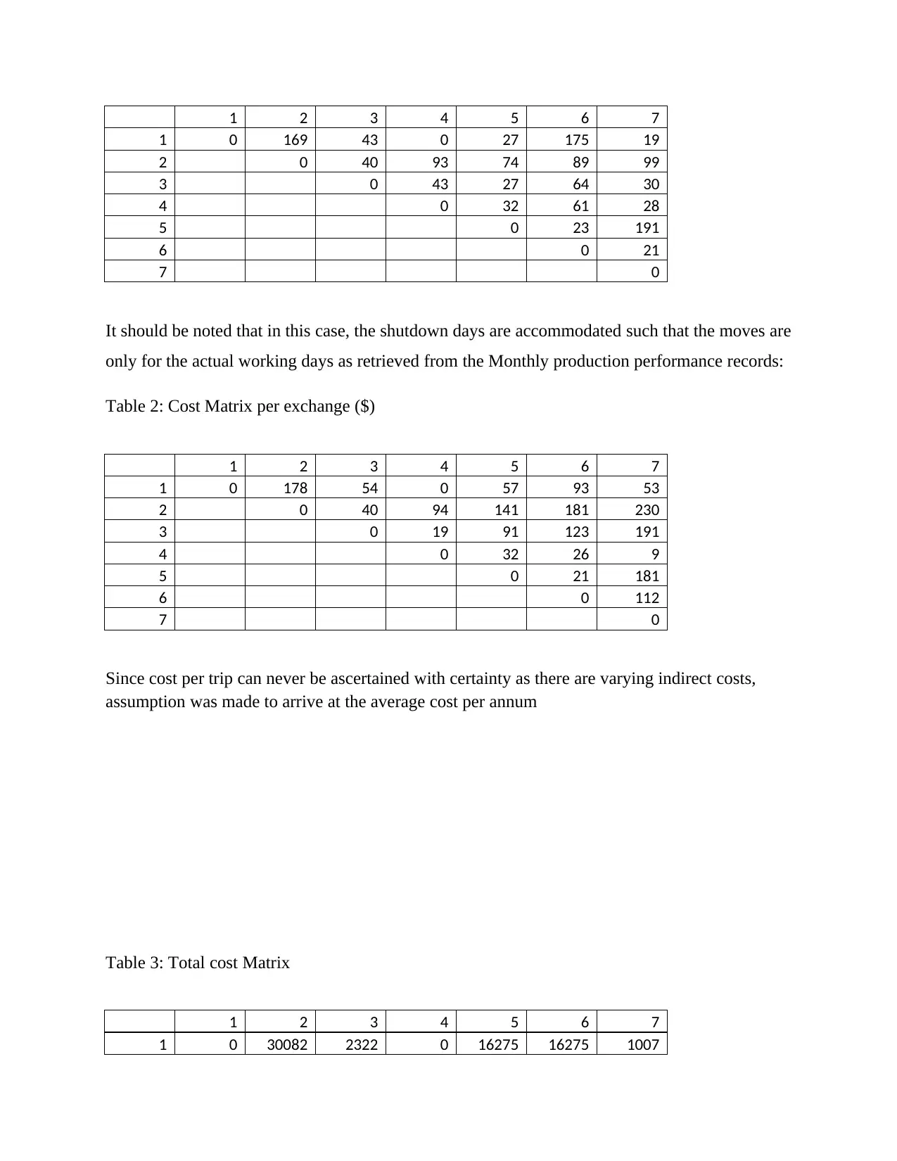
are tabulated in table 1; cost per exchange for each department is depicted in table 2. Note that
the diagonal moves can be allowed so that departments 2 and 3, and 3 and 4, are considered
adjacent. Given this information, our first step is to illustrate the interdepartmental flow by a
model. This provides the basic layout pattern. The second step is to determine the cost of this
layout by multiplying the material handling cost by the number of loads moved between each
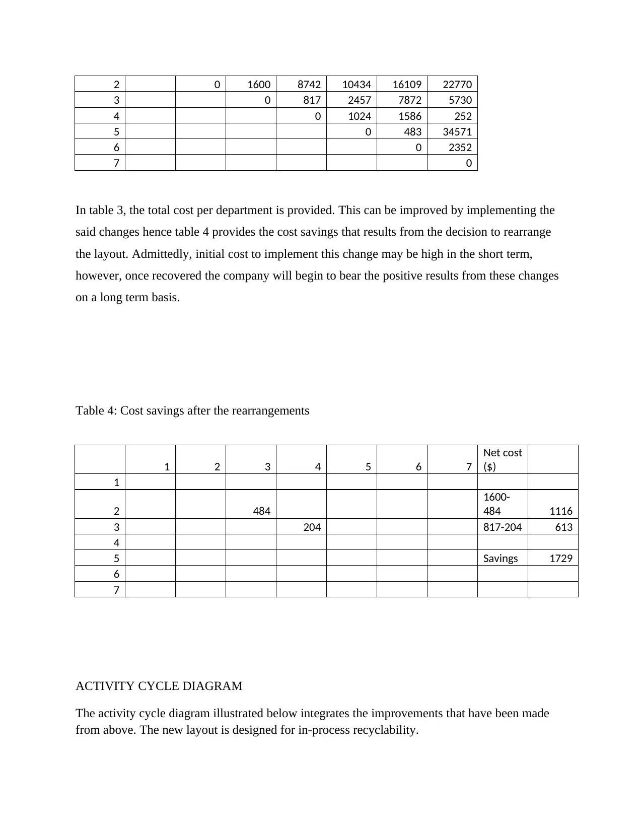
pair of departments; table 3 from routing sheets presents this information, which is derived as
follows: The annual material handling cost between Departments1 and 2 is $30082 ($178 × 169
moves), $16275 between Departments 1and 5 ($57× 27 moves), $1007 between Departments 1
and 7 ($53 × 19 moves), $22770 between Departments 2 and 7 ($99 × 230), and so forth.
Table 1: Departmental Exchanges per annum
⊘ This is a preview!⊘
Do you want full access?
Subscribe today to unlock all pages.

Trusted by 1+ million students worldwide
1 2 3 4 5 6 7
1 0 169 43 0 27 175 19
2 0 40 93 74 89 99
3 0 43 27 64 30
4 0 32 61 28
5 0 23 191
6 0 21
7 0
It should be noted that in this case, the shutdown days are accommodated such that the moves are
only for the actual working days as retrieved from the Monthly production performance records:
Table 2: Cost Matrix per exchange ($)
1 2 3 4 5 6 7
1 0 178 54 0 57 93 53
2 0 40 94 141 181 230
3 0 19 91 123 191
4 0 32 26 9
5 0 21 181
6 0 112
7 0
Since cost per trip can never be ascertained with certainty as there are varying indirect costs,
assumption was made to arrive at the average cost per annum
Table 3: Total cost Matrix
1 2 3 4 5 6 7
1 0 30082 2322 0 16275 16275 1007
Paraphrase This Document
Need a fresh take? Get an instant paraphrase of this document with our AI Paraphraser
2 0 1600 8742 10434 16109 22770
3 0 817 2457 7872 5730
4 0 1024 1586 252
5 0 483 34571
6 0 2352
7 0
In table 3, the total cost per department is provided. This can be improved by implementing the
said changes hence table 4 provides the cost savings that results from the decision to rearrange
the layout. Admittedly, initial cost to implement this change may be high in the short term,
however, once recovered the company will begin to bear the positive results from these changes
on a long term basis.
Table 4: Cost savings after the rearrangements
1 2 3 4 5 6 7
Net cost
($)
1
2 484
1600-
484 1116
3 204 817-204 613
4
5 Savings 1729
6
7
ACTIVITY CYCLE DIAGRAM
The activity cycle diagram illustrated below integrates the improvements that have been made
from above. The new layout is designed for in-process recyclability.
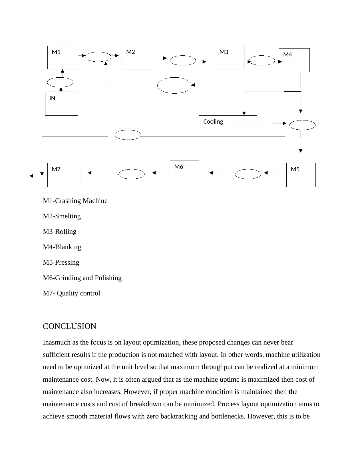
M1-Crashing Machine
M2-Smelting
M3-Rolling
M4-Blanking
M5-Pressing
M6-Grinding and Polishing
M7- Quality control
CONCLUSION
Inasmuch as the focus is on layout optimization, these proposed changes can never bear
sufficient results if the production is not matched with layout. In other words, machine utilization
need to be optimized at the unit level so that maximum throughput can be realized at a minimum
maintenance cost. Now, it is often argued that as the machine uptime is maximized then cost of
maintenance also increases. However, if proper machine condition is maintained then the
maintenance costs and cost of breakdown can be minimized. Process layout optimization aims to
achieve smooth material flows with zero backtracking and bottlenecks. However, this is to be
M1
M6
M3M2 M4
M7
IN
Cooling
M5
⊘ This is a preview!⊘
Do you want full access?
Subscribe today to unlock all pages.

Trusted by 1+ million students worldwide
done in continuous improvement fashion such that real time simulation techniques can further be
applied to cement the adopted analytical optimization technique proposed above. Certainly, these
changes may appear simple but in the long run they can make a huge difference especially if
implemented appropriately.
BIBLOGRAPHY
AMC. (2018). Our Manufacturing Process - Our Products - About | AMC. [online] Available at:
http://www.amcsa.co.za/en/about-amc/our-products/our-manufacturing-process/
[Accessed 30 Mar. 2018].
Falkcoppercookware.com. (2018). Our Manufacturing Process - Falk Copper Cookware.
[online] Available at: http://www.falkcoppercookware.com/info/technical [Accessed 30
Mar. 2018].
Igboanugo, A. and Amiebenomo, S. (2007). Design of Process Layout for a Pilot Alkyd Resin
Production Plant. Advanced Materials Research, 18-19, pp.435-441.
Netmba.com. (2018). Process Flow Structure. [online] Available at:
http://www.netmba.com/operations/process/structure/ [Accessed 30 Mar. 2018].
Pourhassan, M. and Raissi, S. (2017). An integrated simulation-based optimization technique for
multi-objective dynamic facility layout problem. Journal of Industrial Information
Integration, 8, pp.49-58.
Production Planning & Control. (2013). Production Planning & Control, 24(8-9), pp.866-866.
1 out of 10
Your All-in-One AI-Powered Toolkit for Academic Success.
+13062052269
info@desklib.com
Available 24*7 on WhatsApp / Email
![[object Object]](/_next/static/media/star-bottom.7253800d.svg)
Unlock your academic potential
Copyright © 2020–2025 A2Z Services. All Rights Reserved. Developed and managed by ZUCOL.