State Chart Diagram for Oral-B Braun 5000 Toothbrush & SmartScreen
VerifiedAdded on 2023/06/13
|10
|1850
|262
AI Summary
This case study explains the state chart diagram for Oral-B Braun 5000 Toothbrush & SmartScreen. It covers the functionality of the toothbrush, state flow diagram, state transition diagram, and recommendations.
Contribute Materials
Your contribution can guide someone’s learning journey. Share your
documents today.

UNIVERSITY
AFFILIATION
2018
FACULTY OR DEPARTMENT
COURSE ID & NAME
STUDENT NAME
STUDENT REGISTRATION NUMBER
PROFESSOR (TUTOR)
DATE OF SUBMISSION
AFFILIATION
2018
FACULTY OR DEPARTMENT
COURSE ID & NAME
STUDENT NAME
STUDENT REGISTRATION NUMBER
PROFESSOR (TUTOR)
DATE OF SUBMISSION
Secure Best Marks with AI Grader
Need help grading? Try our AI Grader for instant feedback on your assignments.
Oral-B Braun 5000 Electric Toothbrush
STATE CHART DIAGRAM FOR ORAL-B BRAUN 5000
TOOTHBRUSH & SMARTSCREEN
TABLE OF CONTENTS
INTRODUCTION.......................................................................................................................................2
FUNCTIONALITY OF ORAL-B BRAUN TOOTHBRUSH.....................................................................3
FUNCTIONALITY OF ORAL-B BRAUN SMARTGUIDE......................................................................3
STATE FLOW DIAGRAM........................................................................................................................4
STATE TRANSITION DIAGRAM............................................................................................................6
DISCUSSION.............................................................................................................................................7
RECOMMENDATIONS.............................................................................................................................8
CONCLUSION...........................................................................................................................................8
REFERENCES............................................................................................................................................8
1
Oral-B Braun 5000 Electric Toothbrush
INTRODUCTION
The software modelling methodologies are mainly implemented using the unified
modelling language. Some of the common software intensive systems such as medical
electronics, transportation systems, telecommunication systems, enterprise information systems,
and distributed web-based services are implemented using the modelling scheme. Some other
non-software related systems are modelled using UML such as workflow, process structures and
hardware design especially for networks. Some of the UML models used are Use Case diagrams,
the sequence diagrams, collaboration diagrams, state chart diagrams, activity diagrams,
component diagrams, deployment diagrams, and object diagrams work together to represent the
systems and all its relevant specifications. UML is useful when incorporated to a development
process that has a case study that is use case driven, architecture centric, iterative and
incremental in nature.
In this case study, the Oral B Braun 5000 SmartScreen Toothbrush is recommended for use by
persons above the age of 3 years. It is recommended for use by persons who have reduced
physical, sensory, and mental abilities. The user may not have the necessary experience or
knowledge and as such may require to have been given supervision or instruction concerning the
use of the appliance in a safe way. This Toothbrush has an extended feature beyond the electric
brushing; it can connect to one’s smartphone. The connection to the phone requires
communication via an application. The radio transmission is deactivated to avoid occurrence of
electromagnetic interference and compatibility conflicts.
The toothbrush is comprised of,
Power Mode selection (On/Off)
Pressure Sensor light
Charge Indicator light
Low charge indicator light
Charging unit which has the basic charger and brush head compartment with
protective cover.
Smartphone holder depending on the model
2
Oral-B Braun 5000 Electric Toothbrush
Handle that is fitted with radio communication technology (Bluetooth
Technology)
FUNCTIONALITY OF ORAL-B BRAUN TOOTHBRUSH
The toothbrush has a battery unit or charging unit which stores the power for use.
It has a SmartScreen which allows the toothbrush to connect to the phone App. The
smartphone App can run on iOS or Android Operating Systems. The App guides one
through the entire Bluetooth pairing procedure.
The radio connectivity is limited to Bluetooth wireless technology.
The toothbrush is operated by turning it ON at the power mode selection point. The
moment the toothbrush is turned ON it connects to the application on the Smartphone and
starts sharing information.
The Bluetooth 4.0 wireless technology is employed to enable connection with the iOS or
Android based smartphone. The smartphone needs to be in a close proximity of about 5m
distance.
FUNCTIONALITY OF ORAL-B BRAUN SMARTGUIDE
The user guide is keen to mention all the hazards involved to ensure maximum safety
of the users.
It is recommended that the user deactivates the radio transmission after turning off the
toothbrush. Turning off the Toothbrush is done by pressing the on/off button for a
period of 3 seconds. A user guide on the operation of the toothbrush is available on
the smartphone app available from either on Android or iOS play store.
After brushing, it is recommended that the user brushes the head under running water
with the handle switched on. The device is switched off and the brush head is
removed. The handle and the brush head are cleaned separately.
In software engineering, the modelling takes the approach of object oriented modelling. It
performs a business modelling, object modelling, analysis and design, and coding alongside unit
or system testing. The steps of this type of modelling is based on the domain analysis, the
3
Secure Best Marks with AI Grader
Need help grading? Try our AI Grader for instant feedback on your assignments.
Oral-B Braun 5000 Electric Toothbrush
product definition and the requirement analysis. When the design is ready, the product can be
integrated, validated, maintained and effectively managed. The state machine is a UML construct
that allows for visualization, specification, construction and documentation of the artefacts of the
software based system. The state charts are widely incorporated in many software designs
especially where the system is analyzed as a modular design. The challenge is to extend our
SXM based techniques to class testing. The designs seek to compile the empirical evidence about
their effectiveness and more so help in the class testing of system based on the requirements
design or documentation. The empirical evidence shows that the state-based testing is more
effective than random testing. It is not likely to be sufficient to use unless the state diagram is
straightforward as illustrated in the figure above. The state charts are used in modelling, a
common practice in engineering designs. The use of state transition diagram is to enable the
visualization of the operation of the real-life system, it specifies the structure and the behaviour
as well as providing a template to enable one to understand and implement the system.
STATE FLOW DIAGRAM
The state is an abstraction of the attribute values and link status. The component specifies
the way the event reacts with other events when it receives a signal or a call. It specifies the
events that are key or sensitive to the operation of the system. Some of the basic or common
events may be ignored within a state and the activities that the object performs while in the given
state. The state duration must be greater than zero at any given instance to indicate the duration
an activity is processed.
4
Oral-B Braun 5000 Electric Toothbrush
Brush Mode
End Brush
Mode
Oral-BΡ
ToothBrush
Power On
Start Oral-BΡ
Smart App
Display App
Instructions
Brush 4
Quadrants
Store Brushing
Data on App
Finish Brushing
Power Off
Store Away
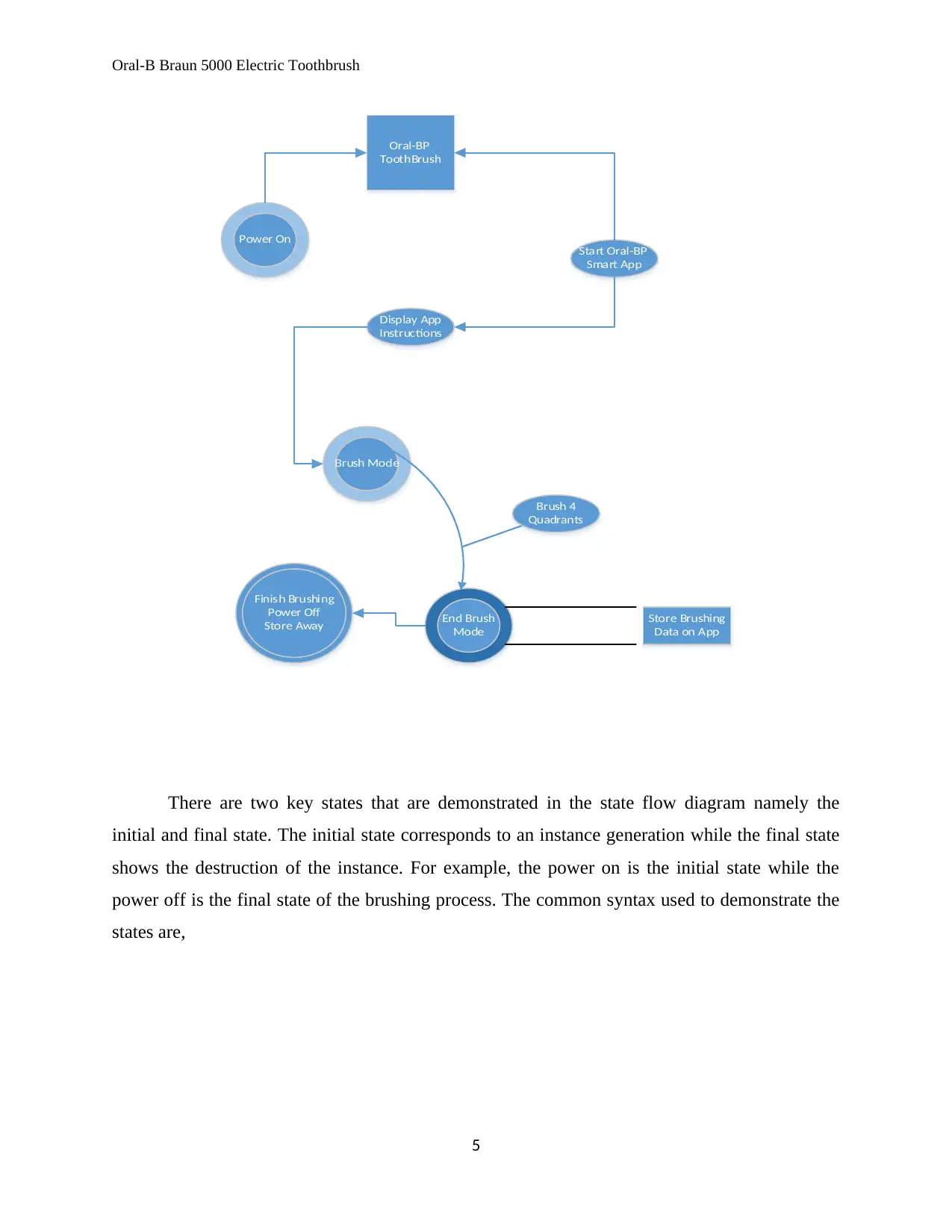
There are two key states that are demonstrated in the state flow diagram namely the
initial and final state. The initial state corresponds to an instance generation while the final state
shows the destruction of the instance. For example, the power on is the initial state while the
power off is the final state of the brushing process. The common syntax used to demonstrate the
states are,
5
Brush Mode
End Brush
Mode
Oral-BΡ
ToothBrush
Power On
Start Oral-BΡ
Smart App
Display App
Instructions
Brush 4
Quadrants
Store Brushing
Data on App
Finish Brushing
Power Off
Store Away
There are two key states that are demonstrated in the state flow diagram namely the
initial and final state. The initial state corresponds to an instance generation while the final state
shows the destruction of the instance. For example, the power on is the initial state while the
power off is the final state of the brushing process. The common syntax used to demonstrate the
states are,
5
Oral-B Braun 5000 Electric Toothbrush
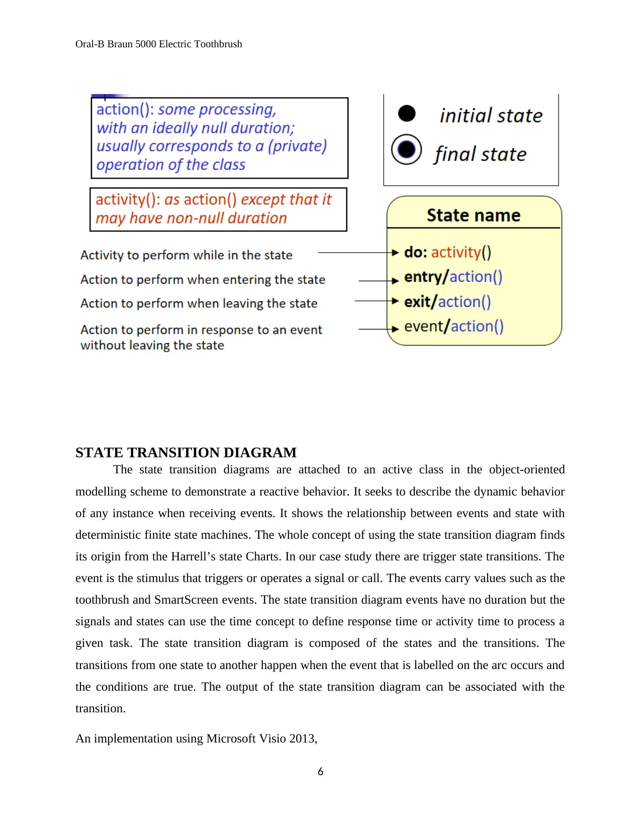
STATE TRANSITION DIAGRAM
The state transition diagrams are attached to an active class in the object-oriented
modelling scheme to demonstrate a reactive behavior. It seeks to describe the dynamic behavior
of any instance when receiving events. It shows the relationship between events and state with
deterministic finite state machines. The whole concept of using the state transition diagram finds
its origin from the Harrell’s state Charts. In our case study there are trigger state transitions. The
event is the stimulus that triggers or operates a signal or call. The events carry values such as the
toothbrush and SmartScreen events. The state transition diagram events have no duration but the
signals and states can use the time concept to define response time or activity time to process a
given task. The state transition diagram is composed of the states and the transitions. The
transitions from one state to another happen when the event that is labelled on the arc occurs and
the conditions are true. The output of the state transition diagram can be associated with the
transition.
An implementation using Microsoft Visio 2013,
6
Paraphrase This Document
Need a fresh take? Get an instant paraphrase of this document with our AI Paraphraser
Oral-B Braun 5000 Electric Toothbrush
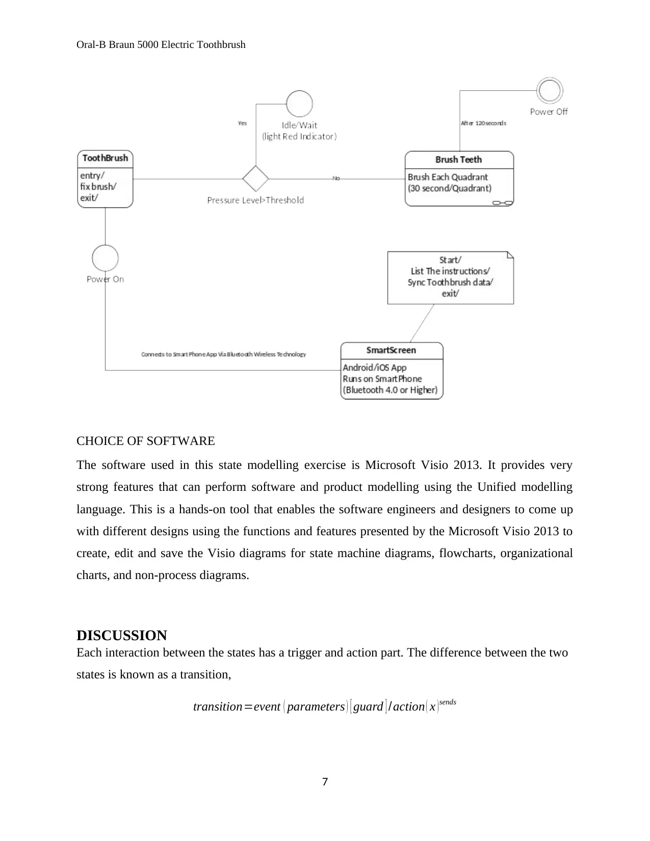
CHOICE OF SOFTWARE
The software used in this state modelling exercise is Microsoft Visio 2013. It provides very
strong features that can perform software and product modelling using the Unified modelling
language. This is a hands-on tool that enables the software engineers and designers to come up
with different designs using the functions and features presented by the Microsoft Visio 2013 to
create, edit and save the Visio diagrams for state machine diagrams, flowcharts, organizational
charts, and non-process diagrams.
DISCUSSION
Each interaction between the states has a trigger and action part. The difference between the two
states is known as a transition,
transition=event ( parameters ) [ guard ] /action ( x ) sends
7
Oral-B Braun 5000 Electric Toothbrush
The Boolean condition has been captured using the decision symbol. When the user applies too
much pressure, the brush needs to pause the brushing process, sends out an indication on the
indicator lights (red light), until the pressure reduces and the brushing proceeds. The action is
performed while traversing the transition (Jean-Paul, 2004). The action gives the signals that are
sent to other objects while traversing the transition. The modest fault detection of the state-based
class testing is the best approach in determining the best model of the system. The functional
testing, on the other hand, can be reduced to the state based testing to ensure that the right state
model is developed.
RECOMMENDATIONS
The quality assurance and risk management policy is well described by the Standard
Operation Procedures provided in the manual. The manual does a comprehensive informative
coverage on the health and safety for the toothbrush use. The toothbrush is battery powered and
it is important for a user to dispose of the battery in the proper disposal center for electronic
matter to guarantee environmental conservation.
CONCLUSION
In a nutshell, the system is clearly demonstrated using the state transition diagram to
represent all the operations of the toothbrush and its connection to the SmartScreen. The
toothbrush makes sure that the user does not apply too much pressure on the gums or teeth while
brushing. If the two outgoing transitions are triggered by the same event, the guard is set to be
very exclusive. The events are supposed to be serialized prior to be delivered and the two events
can be carried out simultaneous as long as the connection is maintained. The state transition
diagrams demonstrated above represent the deterministic finite state machines.
8
Oral-B Braun 5000 Electric Toothbrush
REFERENCES
Jean-Paul, R., 2004. State transition Diagrams. 2nd ed. s.l.:s.n.
Oral-B Braun 4000-5000 Electric Toothbrush Manual
USC., State Charts lecture notes,
https://www.sunset.usc.edu/classes/cs599_2000/September21b.ppt
9
REFERENCES
Jean-Paul, R., 2004. State transition Diagrams. 2nd ed. s.l.:s.n.
Oral-B Braun 4000-5000 Electric Toothbrush Manual
USC., State Charts lecture notes,
https://www.sunset.usc.edu/classes/cs599_2000/September21b.ppt
9
1 out of 10
Related Documents


Your All-in-One AI-Powered Toolkit for Academic Success.
+13062052269
info@desklib.com
Available 24*7 on WhatsApp / Email
![[object Object]](/_next/static/media/star-bottom.7253800d.svg)
Unlock your academic potential
© 2024 | Zucol Services PVT LTD | All rights reserved.