Key Design Aspects of Overhead Lines: Construction and Maintenance
VerifiedAdded on 2023/06/11
|14
|4628
|360
Report
AI Summary
This report describes the key design aspects of overhead lines regarding construction and maintenance for the next 30 years, including OHS issues and ongoing operating regimes. It highlights the increasing demand for electricity and the necessity of sophisticated infrastructure for transmission, emphasizing the role of overhead lines in carrying currents from high to low voltage. The report discusses various components of high voltage transmission lines, such as conductors (including ACSR, ACSR/AW, ACSR/SD, ACAR, AAC-1350, and AAAC-6201), insulators (pin type, suspension type), and support structures (galvanized steel frame towers, wooden H-frame, and K-frame towers). Factors influencing the selection of conductors, like span, sag, tension, atmospheric conditions, and permissible power/voltage loss, are also examined. The report also covers the importance of correct tower placement, considering workspace, labor availability, terrain, and right-of-way access, alongside the necessity of plane profile drawings and structure spotting. Key steps in spotting structures, including drawing plane profiles, establishing sag templates, and considering conductor clearance, are highlighted. Finally, it emphasizes the importance of burying towers to specified depths for stability.
Describe the key design aspects of a given overhead line regarding the construction and
maintenance of such a line for the next 30 years (including OHS issues and ongoing
operating regimes)
In this modern era, there is a huge leap in technology. The technology is improving with each
passing day with the invention of new devices and improvements of existing ones which are
making human life easier, comfortable and healthy day by day. As the number of electrical
gadgets are increasing the demand for electricity is also increasing. In order to meet the
increasing demand of electricity the production of electric current needs to be raised. As the
production increases there is a need to have sophisticated infrastructure to transmit the
produced current to the targeted areas (Lazaropoulos, 2014). Transmitting the current requires
overhead lines to be in place. These overhead lines can be of any type and can be located
anywhere. They carry currents ranging from high to low voltage. The overhead lines which
carry very high voltage current that is there the current directly comes to them from the
power stations and are basically placed in the fields. They carry currents which can be in
thousand volts. The overhead lines which carry current of low voltage that is in hundreds of
volts are mainly located inside cities or towns or villages.
Overhead lines are those structures which are used to transmit electrical power and distribute
them over a long distance. The overhead power lines consists of more than one conductor
which are suspended by the poles or towers. As the losses in transmission is less thorough
overhead wires due to the insulation that is provided by the air. As air provides insulation to
the transmitting current, so the transmission of current with the help of overhead wires is a lot
cost method of power transmission and is used to carry and distribute power over long
distances. Overhead lines needs support as they can’t hang in the air. The towers are there to
provide them the required support. Overhead wires are mainly carried by towers which can
Paraphrase This Document
Need a fresh take? Get an instant paraphrase of this document with our AI Paraphraser
be made from wood, steel, aluminium, concrete structures and sometimes are also made from
reinforced plastics. The transmission wires which are used to transmit current are generally
made from aluminium. These wires can be plain wires or can be of composite materials such
as carbon and glass fibre or can be reinforced with steel. Sometimes copper wires are also
used to transmit medium and low voltage currents to the customers. The overhead wires are
mainly designed to have enough clearance between the ground and the high current carrying
wires so that there is no contact with the line. Clearance between the wires are also required
so that they wires doesn’t come in contact with each other during storms. They are designed
keeping in mind the load that can be imposed to them by earthquakes and ice deposits. In
these days overhead wires are widely used to transmit and distribute current. These overhead
wires are capable of carrying currents above 765,000 volts (Kiessling et. al,. 2014).
The overhead power lines can be classified into different groups depending upon the ranges
of voltage they carry:
Low voltage (LV) - These generally carry voltage which are less than 1kV. These are used
for connection in homes or in small utility services.
Medium voltage (MV) – They generally carry voltage between 1kV and 69 kV. They are
used to distribute current in rural and urban areas.
High voltage (HV) – They are used to carry current at lower voltage which is less than 100
kV. They are also used for sub transmission or transmission at voltages such as 115 kV and
138 kV. It is used to transmit power in bulk quantity.
Extra high voltage (EHV) – They carry voltages from 345 kV to about 800 kV. They are used
to transmit power to very long distances. The power is transmitted at very high frequency.
Ultra high voltage (UHV) – it carries power which is more than 800 kV.
Key design aspects of overhead lines regarding construction
The main purpose of transmission line or distribution line is to carry power from one point to
another (Gönen, 2014). Some of the characteristics which a transmission line should possess
are as follows:
Voltage should be constant over the entire length of the line.
The losses should be as minimal as possible. Decreasing the amount of loss will
increase the transmission efficiency of the overhead line.
There should not be any heating due to the copper losses.
There are many components in a high voltage transmission line. Some of them are as
follows:
1. Conductors
Conductors are always kept bare as they have natural insulation which is
provided by air.
Conductors provide vital link in the transmission and distribution system.
They are designed to meet the specified voltage level.
The conductor should be built according to the voltage at which the current is
required to be transmitted. The tension of the line, maximum allowable losses,
and the tension of the line and the maximum thermal capacity of the line should
also be considered.
Factors such as the geographical location, climatic and atmospheric conditions
along with the vibration in the line should also be kept in mind.
Different types of conductors are used to transmit power of different intensities. Some of the
conductors are as follows:
⊘ This is a preview!⊘
Do you want full access?
Subscribe today to unlock all pages.
Trusted by 1+ million students worldwide
I. Aluminium conductor steel reinforced (ACSR) – This conductor is widely used in
these days due to its low cost and high material strength. This type of conductors
mainly have aluminium wires that are wrapped around a steel cylinder. The most
common ACSR that are used in these days are 26/7, 6/1, 54/7 (Douglass et. al,. 2016).
II. ACSR conductor with aluminium clad steel reinforced core (ACSR/AW) – These
conductors are widely used in those environments which have high humidity content
as they don’t corrode.
III. ACSR conductor that is self-damping (ACSR/SD) – These conductors are more
expensive than the ACSR conductors. It has a steel core with two trapezoidal layers of
conductor around it. The wires are made of #6201 aluminium. The structure of the
conductor makes it damp proof against Aeolian vibrations. These have the ability to
be strung at very high tensions.
IV. Aluminium conductor alloy reinforced (ACAR) – It has wire of #1350 aluminium
which is wrapped around a core of #6201 aluminium. These are lighter in weight than
the ACSRs. They are more expensive but possess the same strength as the ACSR
does. These are mainly used in corrosive environments.
V. Aluminium conductor made of #1350 strands (AAC-1350) – These are used when
there is a requirement to transmit electricity to a short distance with a very high
conductivity and minimal loss.
VI. Conductor composed of #6201 aluminium alloy (AAAC-6201) – These conductors
are very stronger. They are lighter in weight than the ACSRs but are predominantly
more expensive than them. These are mainly used when the environment is corrosive
in nature and the transmission is required over long distances.
Factors that are needed to be considered before selecting the type of conductor that is
required for an overhead transmission line are as follows:
Paraphrase This Document
Need a fresh take? Get an instant paraphrase of this document with our AI Paraphraser
Amount of span and sag that is required
The tension that can be applied on the conductor
Nature of the atmosphere that is corrosive or not
If there is any kind of vibration in the line or not
Permissible limit of power loss
Permissible limit of voltage loss
The climatic conditions at the site
In order to transmit power with minimal losses it is important to choose the right size of the
conductor. The factors which are taken into consideration while choosing the size of the
conductors are as follows:
Voltage drop consideration: The conductor meets the minimum size requirement but
transmits power with an acceptable loss. The loss is expressed in terms of maximum voltage
drop of 5% (Wang et. al., 2016). The impedance of the total series connection is equal to the
maximum voltage drop that is allowed and then dividing it with the maximum load current.
Therefore the equation can be written as
Z = R + jX = V/ I max
Thermal capacity: The conductor should have the ability to transmit the power without being
getting overheated during long period of time. It is assumed that the conductor can withstand
temperatures up to 75 degree Celsius (Qin et. al,. 2015). This should not decrease the strength
of the conductor. As the temperature crosses this range the strength of the conductor is
assumed to be getting decreased.
Economic considerations: The conductors are rarely sized to meet the minimum requirement.
The total cost per kilometre should be taken into account. There are also energy losses
during the transmission of the power. Compensations are needed to be provided for load
growth.
2. Insulators
There are mainly two type of insulator which are used. Pin type and suspension type. Tension
type insulator is also there but are rarely used. Insulators are mainly used to support and
anchor the conductors. They also insulate the conductors from the ground. These are mainly
made up glass or porcelain and in some cases ceramic is also used.
3. Support structures
These are the structures which are used to carry the overhead lines and keeps the conductors
at a safer height from the ground. They also helps to maintain distance between the
conductors. The support structures are constructed depending upon the budget that has been
allocated. The budget takes into consideration labour costs, transportation costs as well as
design and material cost. Generally galvanised steel frame towers and wooden H-frame and
K-frame towers are commonly used (Wang et. al., 2015). It is very important to place the
towers correctly. Erecting the towers is a challenging as well as one of the important task of
transmission line construction. The way the towers will be erected depends on the following
conditions:
Workspace
Availability and experience of the labours
Time that is given to complete the project
Terrain
Space available for work
⊘ This is a preview!⊘
Do you want full access?
Subscribe today to unlock all pages.
Trusted by 1+ million students worldwide
In addition to all these factors there are also some factors which are important to be
considered while choosing the method of construction. The factors are:
The type of structure that is needed to be erected
The natural divisions that are available
The dimensions of the natural divisions
The conditions to access the right of way
The above factors also helps to decide whether maximum labour minimum equipment or
minimum labour maximum equipment would be favourable and feasible.
Location of poles and structures: Poles and structures have to be located in observance of the
right way. It is very important to draw a plan profile drawing before starting work on the
field. These drawings shows topographical contour maps of the terrains along with the right
of way. These drawings helps to decide the elevation of the tower. The drawing works as an
pre-planning of the works and helps to decide what needed to be done afterwards. They also
help to find the way of certain challenges that are posed during the phase of the construction.
These are used to complete the work with respect to structure spotting (Xu et. al,. 2014). The
following steps should be taken into consideration while spotting structures:
Drawing the plane profile drawing on a certain fixed scale
Establishing the sag template on the same drawing along with the same scale
Table showing the conductor clearance to the ground as well as with the other
overhead lines
Deciding vertical and horizontal span limitations due to strength requirements and
clearances
Paraphrase This Document
Need a fresh take? Get an instant paraphrase of this document with our AI Paraphraser
It is important that the towers are needed to be buried to a certain specified depth so that they
doesn’t collapse. The depth depends upon certain conditions and can range from 6 feet up to
certain hundred feet’s (Thrash et. al., 2014).
There are basically two type of towers are used. The types are as follows:
a) Towers used for straight runs
b) Towers used when bends have to be made in the path of the line (Deviation towers)
Putting the deviation towers at their specified place is very important and a risky job too.
Guyed wires and blocks are used to balance the tensile forces on the tower. If two forces act
on the tower a resultant force gets generated and the guyed wire is used to counteract the
resultant force so that the tower doesn’t collapse.
Maintaining the overhead power lines for the next thirty years (including OHS issues
and ongoing operating regimes)
In order to ensure their full efficiency and longer shelf life it is required that the established
overhead line gets their periodical maintenance time to time. High and ultra-high voltage
infrastructure are the future of electrical grids as they have very large capacity, can transmit
power to a longer distance and has very high amount of efficiency. As public health,
transportation, water supply and other energy related assets, transmission lines are also a part
of so called “critical infrastructures” as they provide essential services for the economy and
functioning of a society. Therefore maintaining the overhead power line is very important
along with keeping in mind the OHS (Occupational Health and Safety) issues (Kiessling et. al.,
2018).
There are various ways for preventive and predictive maintenance of the overhead
transmission lines. Patrolling the lines thoroughly. Digital photography of the lines are also
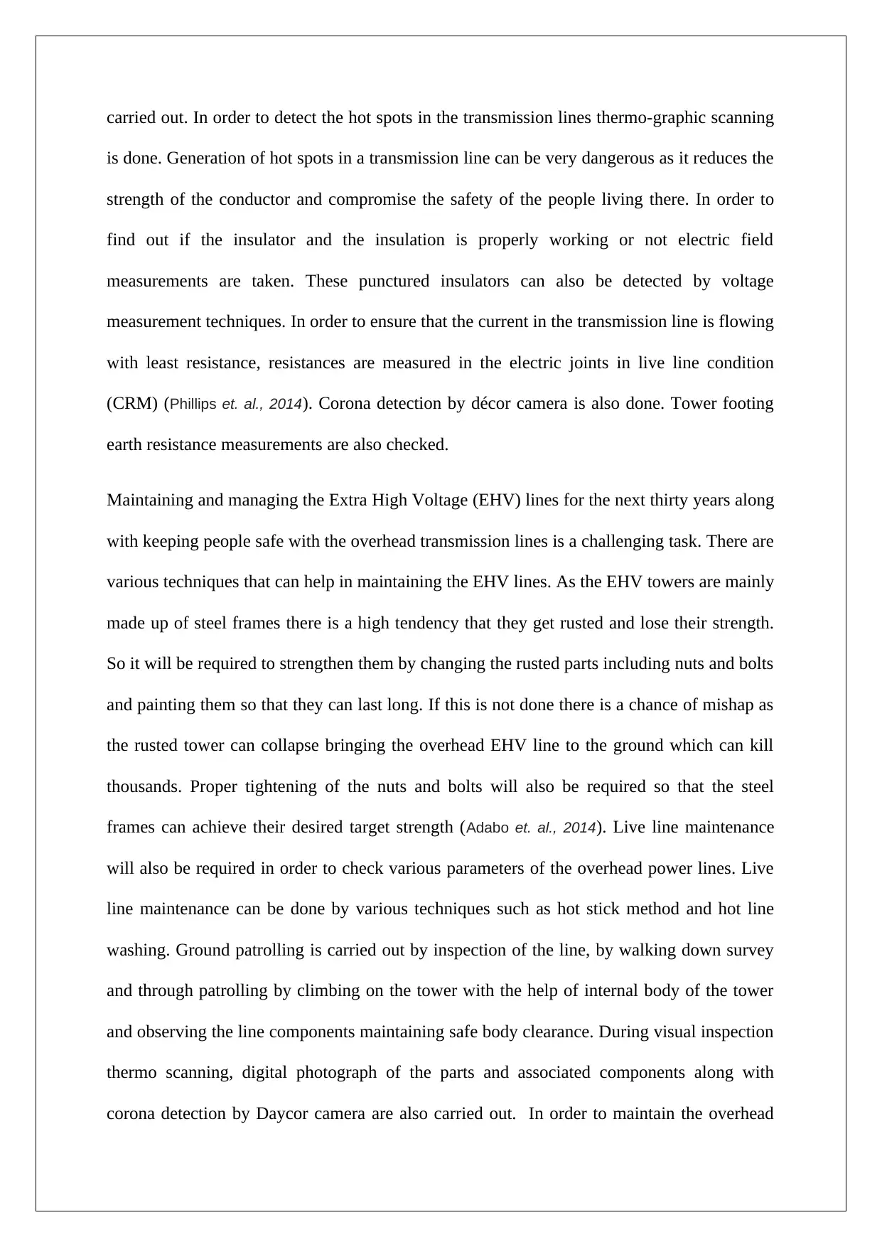
carried out. In order to detect the hot spots in the transmission lines thermo-graphic scanning
is done. Generation of hot spots in a transmission line can be very dangerous as it reduces the
strength of the conductor and compromise the safety of the people living there. In order to
find out if the insulator and the insulation is properly working or not electric field
measurements are taken. These punctured insulators can also be detected by voltage
measurement techniques. In order to ensure that the current in the transmission line is flowing
with least resistance, resistances are measured in the electric joints in live line condition
(CRM) (Phillips et. al., 2014). Corona detection by décor camera is also done. Tower footing
earth resistance measurements are also checked.
Maintaining and managing the Extra High Voltage (EHV) lines for the next thirty years along
with keeping people safe with the overhead transmission lines is a challenging task. There are
various techniques that can help in maintaining the EHV lines. As the EHV towers are mainly
made up of steel frames there is a high tendency that they get rusted and lose their strength.
So it will be required to strengthen them by changing the rusted parts including nuts and bolts
and painting them so that they can last long. If this is not done there is a chance of mishap as
the rusted tower can collapse bringing the overhead EHV line to the ground which can kill
thousands. Proper tightening of the nuts and bolts will also be required so that the steel
frames can achieve their desired target strength (Adabo et. al., 2014). Live line maintenance
will also be required in order to check various parameters of the overhead power lines. Live
line maintenance can be done by various techniques such as hot stick method and hot line
washing. Ground patrolling is carried out by inspection of the line, by walking down survey
and through patrolling by climbing on the tower with the help of internal body of the tower
and observing the line components maintaining safe body clearance. During visual inspection
thermo scanning, digital photograph of the parts and associated components along with
corona detection by Daycor camera are also carried out. In order to maintain the overhead
⊘ This is a preview!⊘
Do you want full access?
Subscribe today to unlock all pages.
Trusted by 1+ million students worldwide
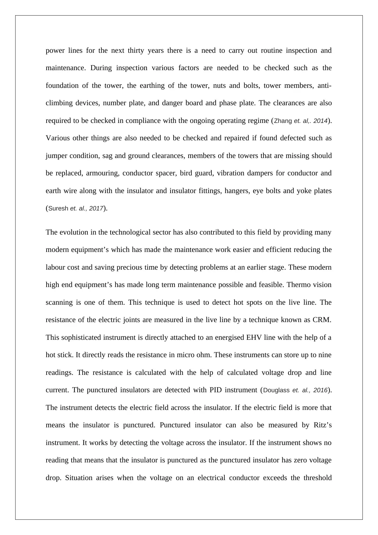
power lines for the next thirty years there is a need to carry out routine inspection and
maintenance. During inspection various factors are needed to be checked such as the
foundation of the tower, the earthing of the tower, nuts and bolts, tower members, anti-
climbing devices, number plate, and danger board and phase plate. The clearances are also
required to be checked in compliance with the ongoing operating regime (Zhang et. al,. 2014).
Various other things are also needed to be checked and repaired if found defected such as
jumper condition, sag and ground clearances, members of the towers that are missing should
be replaced, armouring, conductor spacer, bird guard, vibration dampers for conductor and
earth wire along with the insulator and insulator fittings, hangers, eye bolts and yoke plates
(Suresh et. al., 2017).
The evolution in the technological sector has also contributed to this field by providing many
modern equipment’s which has made the maintenance work easier and efficient reducing the
labour cost and saving precious time by detecting problems at an earlier stage. These modern
high end equipment’s has made long term maintenance possible and feasible. Thermo vision
scanning is one of them. This technique is used to detect hot spots on the live line. The
resistance of the electric joints are measured in the live line by a technique known as CRM.
This sophisticated instrument is directly attached to an energised EHV line with the help of a
hot stick. It directly reads the resistance in micro ohm. These instruments can store up to nine
readings. The resistance is calculated with the help of calculated voltage drop and line
current. The punctured insulators are detected with PID instrument (Douglass et. al., 2016).
The instrument detects the electric field across the insulator. If the electric field is more that
means the insulator is punctured. Punctured insulator can also be measured by Ritz’s
instrument. It works by detecting the voltage across the insulator. If the instrument shows no
reading that means that the insulator is punctured as the punctured insulator has zero voltage
drop. Situation arises when the voltage on an electrical conductor exceeds the threshold
Paraphrase This Document
Need a fresh take? Get an instant paraphrase of this document with our AI Paraphraser
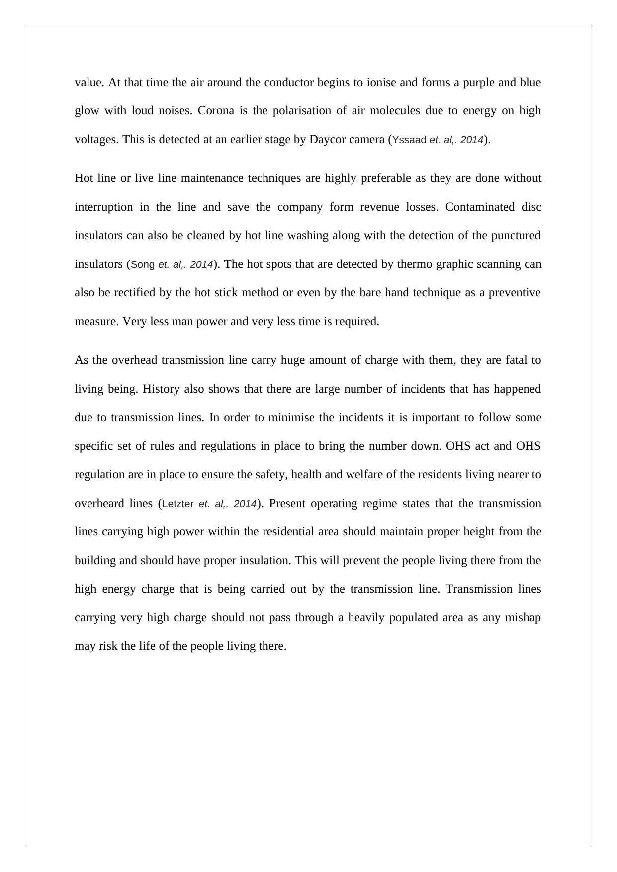
value. At that time the air around the conductor begins to ionise and forms a purple and blue
glow with loud noises. Corona is the polarisation of air molecules due to energy on high
voltages. This is detected at an earlier stage by Daycor camera (Yssaad et. al,. 2014).
Hot line or live line maintenance techniques are highly preferable as they are done without
interruption in the line and save the company form revenue losses. Contaminated disc
insulators can also be cleaned by hot line washing along with the detection of the punctured
insulators (Song et. al,. 2014). The hot spots that are detected by thermo graphic scanning can
also be rectified by the hot stick method or even by the bare hand technique as a preventive
measure. Very less man power and very less time is required.
As the overhead transmission line carry huge amount of charge with them, they are fatal to
living being. History also shows that there are large number of incidents that has happened
due to transmission lines. In order to minimise the incidents it is important to follow some
specific set of rules and regulations in place to bring the number down. OHS act and OHS
regulation are in place to ensure the safety, health and welfare of the residents living nearer to
overheard lines (Letzter et. al,. 2014). Present operating regime states that the transmission
lines carrying high power within the residential area should maintain proper height from the
building and should have proper insulation. This will prevent the people living there from the
high energy charge that is being carried out by the transmission line. Transmission lines
carrying very high charge should not pass through a heavily populated area as any mishap
may risk the life of the people living there.
References
Lazaropoulos, A.G., 2014. Wireless sensor network design for transmission line monitoring, metering,
and controlling: introducing broadband over power lines-enhanced network model (BPLeNM). ISRN
Power Engineering, 2014.
Kiessling, F., Nefzger, P., Nolasco, J.F. and Kaintzyk, U., 2014. Overhead power lines: planning,
design, construction. Springer.
Gönen, T., 2014. Electrical Power Transmission System Engineering: Analysis and Design. CRC
Press.
Douglass, D., Chisholm, W., Davidson, G., Grant, I., Lindsey, K., Lancaster, M., Lawry, D., McCarthy,
T., Nascimento, C., Pasha, M. and Reding, J., 2016. Real-time overhead transmission-line monitoring
for dynamic rating. IEEE Transactions on Power Delivery, 31(3), pp.921-927.
Wang, W., Huang, X., Tan, L., Guo, J. and Liu, H., 2016. Optimization Design of an Inductive Energy
Harvesting Device for Wireless Power Supply System Overhead High-Voltage Power
Lines. Energies, 9(4), p.242.
Qin, J., Saeedifard, M., Rockhill, A. and Zhou, R., 2015. Hybrid design of modular multilevel
converters for HVDC systems based on various submodule circuits. IEEE Transactions on Power
Delivery, 30(1),
pp.385-394.
Wang, K., Qiu, X., Guo, S. and Qi, F., 2015. Fault tolerance oriented sensors relay monitoring
mechanism for overhead transmission line in smart grid. IEEE Sensors Journal, 15(3), pp.1982-1991.
Xu, Z., Xue, Y. and Zhang, Z., 2014. VSC-HVDC technology suitable for bulk power overhead line
transmission. Proceedings of the CSEE, 34(29), pp.5051-5062.
Thrash Jr, F.R., 2014. Transmission conductors–A review of the design and selection
criteria. Technical Support Article, Southwire Company.(http://www. southwire.
com/support/TransmissionConductoraReviewOfTheDesignandSelectionCrite ria. htm (accessed on
9/8/2014).
⊘ This is a preview!⊘
Do you want full access?
Subscribe today to unlock all pages.
Trusted by 1+ million students worldwide
1 out of 14
Related Documents


Your All-in-One AI-Powered Toolkit for Academic Success.
+13062052269
info@desklib.com
Available 24*7 on WhatsApp / Email
![[object Object]](/_next/static/media/star-bottom.7253800d.svg)
Unlock your academic potential
Copyright © 2020–2025 A2Z Services. All Rights Reserved. Developed and managed by ZUCOL.