A Comprehensive Report on the Kalina Cycle and its Applications
VerifiedAdded on 2022/09/01
|5
|1276
|18
Report
AI Summary
This report provides a detailed analysis of the Kalina cycle, a method developed to convert thermal energy into mechanical energy for power generation, primarily using a mixture of ammonia and water as the working fluid. The report explains the cycle's non-isothermal nature, which contributes to its high efficiency by minimizing isothermal losses. It outlines the cycle's components, including the recuperator, separator, condenser, turbine, and boiler, and discusses its operational model, particularly as a bottoming cycle. The report also addresses the challenges associated with the Kalina cycle and proposes potential modifications. Furthermore, it explores the applications of the Kalina cycle in various contexts, such as steam power plants and waste heat recovery systems, highlighting its potential for efficient energy conversion and its advantages over traditional Rankine cycles. The conclusion emphasizes the cycle's benefits, including its ability to vary pressure and its suitability for low-grade heat sources, making it a promising technology for future energy applications.

Name:
Institution:
Student registration number:
Title: Kalina Cycle
Institution:
Student registration number:
Title: Kalina Cycle
Paraphrase This Document
Need a fresh take? Get an instant paraphrase of this document with our AI Paraphraser

Abstract:
A Kalina cycle is designed to convert thermal energy to mechanical energy which turns the
turbine. The turbine could be coupled to coils which turn in a magnetic field to produce
electricity. It is a very efficient cycle since it is a nonisothermal cycle, hence, it does not
experience isothermal losses. This paper aims at discussing the basic operation of the kalian
cycle, its operational model as a bottoming cycle, challenges facing it and the proposed
modifications.
Introduction
Dr. alexander Kalina developed Kalina Cycle as a method of producing electricity using low
temperatures by changing thermal energy into mechanical energy (Zare & Moalemian, 2017,
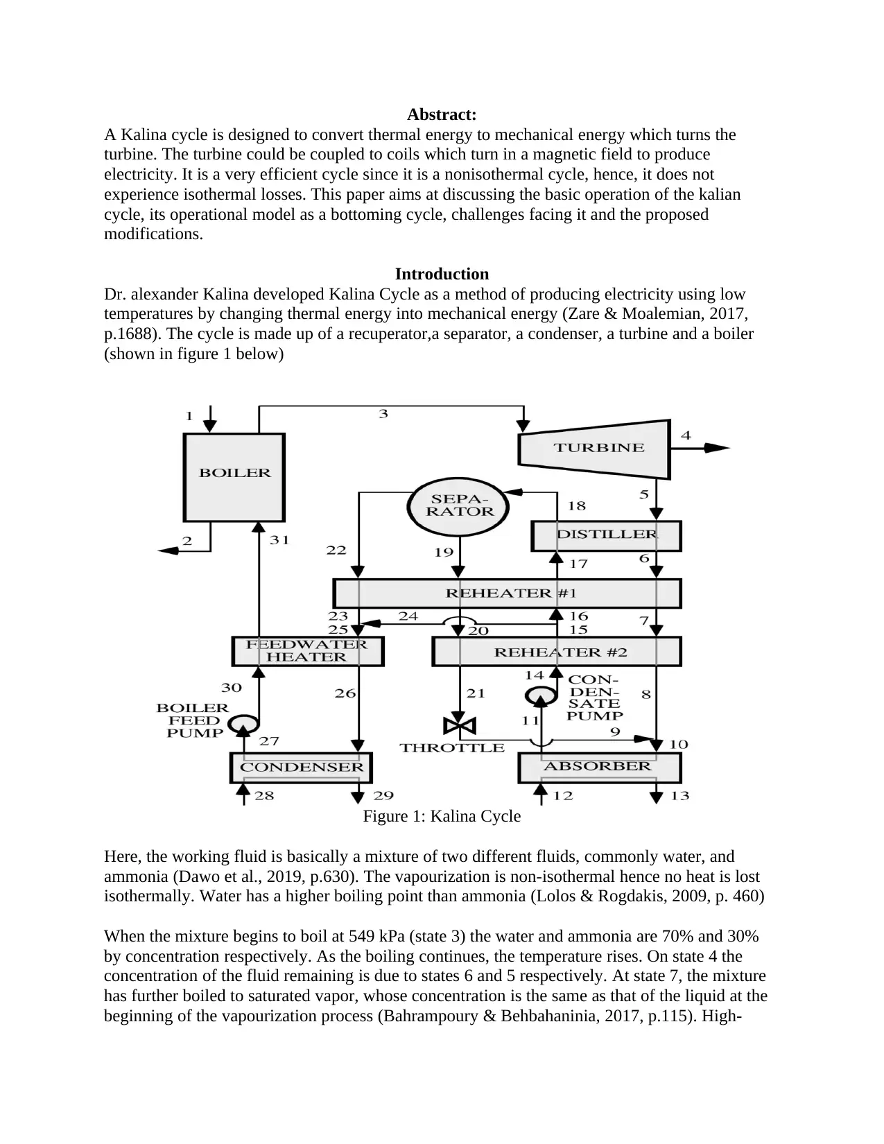
p.1688). The cycle is made up of a recuperator,a separator, a condenser, a turbine and a boiler
(shown in figure 1 below)
Figure 1: Kalina Cycle
Here, the working fluid is basically a mixture of two different fluids, commonly water, and
ammonia (Dawo et al., 2019, p.630). The vapourization is non-isothermal hence no heat is lost
isothermally. Water has a higher boiling point than ammonia (Lolos & Rogdakis, 2009, p. 460)
When the mixture begins to boil at 549 kPa (state 3) the water and ammonia are 70% and 30%
by concentration respectively. As the boiling continues, the temperature rises. On state 4 the
concentration of the fluid remaining is due to states 6 and 5 respectively. At state 7, the mixture
has further boiled to saturated vapor, whose concentration is the same as that of the liquid at the
beginning of the vapourization process (Bahrampoury & Behbahaninia, 2017, p.115). High-

temperature exhaust from the turbine is the source of heat for the water-ammonia mixture for
recovering heat. The mixture absorbs heat, vaporizes hence driving the turbine. The diluted fluid
is then reconcentrated and rechanneled to the turbine. The use of a mixture in power cycles
allows for changes in concentration throughout the cycle by distillation. This allows for rich
concentration in the boiler and leaner concentration in the condenser (Kalina, 2017, p.234).
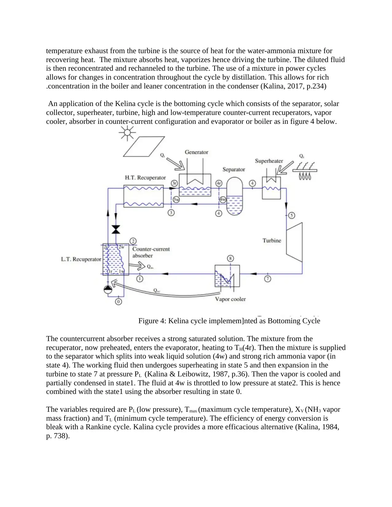
An application of the Kelina cycle is the bottoming cycle which consists of the separator, solar
collector, superheater, turbine, high and low-temperature counter-current recuperators, vapor
cooler, absorber in counter-current configuration and evaporator or boiler as in figure 4 below.
Figure 4: Kelina cycle implemem]nted as Bottoming Cycle
The countercurrent absorber receives a strong saturated solution. The mixture from the
recuperator, now preheated, enters the evaporator, heating to TH(4r). Then the mixture is supplied
to the separator which splits into weak liquid solution (4w) and strong rich ammonia vapor (in
state 4). The working fluid then undergoes superheating in state 5 and then expansion in the
turbine to state 7 at pressure PL (Kalina & Leibowitz, 1987, p.36). Then the vapor is cooled and
partially condensed in state1. The fluid at 4w is throttled to low pressure at state2. This is hence
combined with the state1 using the absorber resulting in state 0.
The variables required are PL (low pressure), Tmax (maximum cycle temperature), XV (NH3 vapor
mass fraction) and TL (minimum cycle temperature). The efficiency of energy conversion is
bleak with a Rankine cycle. Kalina cycle provides a more efficacious alternative (Kalina, 1984,
p. 738).
⊘ This is a preview!⊘
Do you want full access?
Subscribe today to unlock all pages.

Trusted by 1+ million students worldwide

Conclusion
To achieve better power conversion, the Kalina cycle may be inevitable. This is due to its high
notch efficiency and ability to vary the pressure as needed. Hence, it is efficient for applications
such as steam power plants. Kalina cycle also poses no challenge when it comes to isothermal
energy loss since the cycle is non-isothermal. It is, therefore, a highly commended cycle for
efficient energy conversion in applications such as steam power plants
Kalina cycle, being an thermal to mechanical energy converter, it is convenient for use in driving
prime movers of power plants. It therefore comes in handy in harnessing work from a low garede
sources of heat heat like geothermal system walls. This is so because most industries is low
grade. Therefore it is possible to undertake waste energy recovery and thus minimize the energy
consumption. That way, energy demand becomes cost effective and the consumption efficient..
As ammonia leaves the turbine, its concentaration is reduced and the condensing temperature
consequently reduces to a value that is reasonable. Distilation, and condensation subsystem,
abbreviated DCSS consists of the condenser, the control system, the separator and the heat
exchanger is used to achieve the change in concentration.
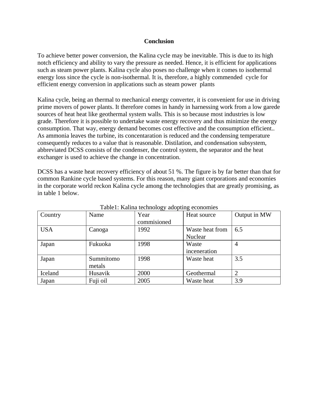
DCSS has a waste heat recovery efficiency of about 51 %. The figure is by far better than that for
common Rankine cycle based systems. For this reason, many giant corporations and economies
in the corporate world reckon Kalina cycle among the technologies that are greatly promising, as
in table 1 below.
Table1: Kalina technology adopting economies
Country Name Year
commisioned
Heat source Output in MW
USA Canoga 1992 Waste heat from
Nuclear
6.5
Japan Fukuoka 1998 Waste
inceneration
4
Japan Summitomo
metals
1998 Waste heat 3.5
Iceland Husavik 2000 Geothermal 2
Japan Fuji oil 2005 Waste heat 3.9
Paraphrase This Document
Need a fresh take? Get an instant paraphrase of this document with our AI Paraphraser

REFERENCES
1. Bahrampoury, R., & Behbahaninia, A. (2017). Thermodynamic
optimization and thermoeconomic analysis of four double pressure Kalina cycles driven
from Kalina cycle system 11. Energy Conversion and Management, 152, 110-
123. https://doi.org/10.1016/j.enconman.2017.09.046
2. Dawo, F., Wieland, C., & Spliethoff, H. (2019). Kalina power plant part
load modeling: Comparison of different approaches to model part load behavior and
validation on real operating data. Energy, 174, 625-
637. https://doi.org/10.1016/j.energy.2019.02.173
3. Hanak, D. P., Biliyok, C., & Manovic, V. (2015). Evaluation and
Modeling of Part-Load Performance of Coal-Fired Power Plant with Postcombustion
CO2 Capture. Energy & Fuels, 29(6), 3833-
3844. https://doi.org/10.1021/acs.energyfuels.5b00591
4. Kalina, A. I. (1984). Combined-Cycle System With Novel Bottoming
Cycle. Journal of Engineering for Gas Turbines and Power, 106(4), 737-
742. https://doi.org/10.1115/1.3239632
5. Kalina, A. L., & Leibowitz, H. M. (1987). Applying Kalina Technology
to a Bottoming Cycle for Utility Combined Cycles. Volume 4: Heat Transfer; Electric
Power. https://doi.org/10.1115/87-gt-35
6. Kalina, J. (2017). TEACHING ENERGY CONVERSION SYSTEMS
THROUGH CASES AND PROJECTS. ICERI2017
Proceedings. https://doi.org/10.21125/iceri.2017.0920
7. Lolos, P., & Rogdakis, E. (2009). A Kalina power cycle driven by
renewable energy sources. Energy, 34(4), 457-
464. https://doi.org/10.1016/j.energy.2008.12.011
8. Zare, V., & Moalemian, A. (2017). Parabolic trough solar collectors
integrated with a Kalina cycle for high temperature applications: Energy, exergy and
economic analyses. Energy Conversion and Management, 151, 681-
692. https://doi.org/10.1016/j.enconman.2017.09.028
1 out of 5
Related Documents
Your All-in-One AI-Powered Toolkit for Academic Success.
+13062052269
info@desklib.com
Available 24*7 on WhatsApp / Email
![[object Object]](/_next/static/media/star-bottom.7253800d.svg)
Unlock your academic potential
Copyright © 2020–2025 A2Z Services. All Rights Reserved. Developed and managed by ZUCOL.


