Design of Owensboro Bridge: Cable-Stayed Bridge Analysis and Simulation
VerifiedAdded on 2023/06/03
|118
|18766
|346
AI Summary
This article discusses the design, analysis, and simulation of the Owensboro cable-stayed bridge, one of the longest cable-stayed spans over the United States waterway system that is found inland. It covers the structural efficiency, aesthetic appeal, and small size of the substructures, and the enhanced stiffness of cable-stayed bridges. The article also discusses the dynamic properties of the bridge, including wind effect and loading from traffic, and the use of finite element modeling and field testing to predict and evaluate the state of the structure.
Contribute Materials
Your contribution can guide someone’s learning journey. Share your
documents today.

ENGIN (DESIGN OF OWENSBORO BRIDGE)
By Name
Course
Instructor
Institution
Location
Date
By Name
Course
Instructor
Institution
Location
Date
Secure Best Marks with AI Grader
Need help grading? Try our AI Grader for instant feedback on your assignments.

ABSTRACT
Cable-stayed bridges have become very popular in the entire world dealing with infrastructure as
well as transport. This popularity is attributed to the structural efficiency, aesthetic appeal, and
small size of the substructures and also enhanced stiffness. There has been very rapid
development in the past 40 years in the cases of the modern cable-stayed bridges. For the cases
of the long span bridges, it is very important to ensure that there is an establishment of the
analytical dynamic properties from the finite element used in predicting other properties. This
also includes the measured dynamic properties from the field testing.
Several research works have been carried out on the properties of the cable-stayed bridges that
are considered dynamic to some extent. In such research works, the obvious structural response
of the bridge due to the wind effect and also loading from the traffic has been identified as the
key factors that affect the design. These two parameters are known to have a great effect on the
dynamic characteristics of the bridge. The structural model that is updating the changes in the
form of calibration has been considered the latest technology to be used. This particular
technology ensures that there is the provision of the worldwide way of evaluating the state of the
structures.

Contents
ABSTRACT...................................................................1
ACKNOWLEDGMENT..................................................2
BACKGROUND............................................................2
INTRODUCTION..........................................................4
Description of the bridge.........................................................................................................................7
Bridge evaluation..........................................................................................................................................................10
Calibration and Finite Element Modeling.....................................................................................................................11
Modeling and testing of the cable................................................................................................................................13
OBJECTIVES...............................................................14
The scope of the work..................................................................................................................................................14
FLOW OF TRAFFIC ENVIRONMENTAL CONDITION OF THE AREA, SOIL CONDITION SUITABLE FOR THE BRIDGE
..................................................................................15
Soil Characteristic Parameters...............................................................................................................17
DESIGN ANALYSIS.....................................................18
Bridge analysis in terms of the structure...............................................................................................19
General information about the bridge.........................................................................................................................20
Design of the girder.....................................................................................................................................................23
Spanning of the structure.............................................................................................................................................25
Tension Comparison of Owensboro.............................................................................................................................32
Design criteria of the cables.........................................................................................................................................36
Substructure..................................................................................................................................................................38
Pylon Design..........................................................................................................................................41
Reinforcement plan for the pylon................................................................................................................................41
Restrainers on the cable...............................................................................................................................................48
ANALYSIS AND SIMULATION OF THE STRUCTURES OF THE BRIDGES 51
Static analysis........................................................................................................................................51
Anchor deflection setting..............................................................................................................................................52
Dynamic analysis...........................................................................................................................................................53
Analysis and design of cable-stayed bridges for the loss of a cable(s)...................................................56
Response and properties of Materials to accidental loss of cable(s).....................................................57
Elastic properties..........................................................................................................................................................57
Plastic Properties..........................................................................................................................................................58
Numerical Simulation of Cable loss.......................................................................................................62
METHOD TO REDUCE THE WIND INDUCED VIBRATION IN THE CABLES 64
Use of Linear and Non- linear dampers.................................................................................................65

Use of Cross-Ties...................................................................................................................................66
Additional Mitigation.............................................................................................................................67
CONCLUSION AND RECOMMENDATIONS................68
Project development................................................71
GHANTT CHART.....................................................................................................................................72
REFERENCES.............................................................73
Secure Best Marks with AI Grader
Need help grading? Try our AI Grader for instant feedback on your assignments.


ACKNOWLEDGMENT
All acclaim and on account of God for aiding, giving and maintaining me through the course of
my examination at the University. I genuinely welcome the help and persistent endeavors of my
primary boss Prof for continually paying special mind to my prosperity through this adventure. A
major thanks to my co-manager for your time and direction. My thankfulness goes to the
structural designing care staff; the Research groups in the library, the IT bolster group and the
FEPS postgraduate group for their assistance through my exams. Words will come up short me
to thank NDDC for their budgetary help over the span of my consider. A major thank you to
such superb partners at the CCE look into focus – I appreciate you all for your expressions of
help, making the workplace a fun place to be in and for tolerating me and my children. Think
about what it worked. I can't, however, thank my mom and sibling for their sponsorship. You
have bolstered me through this voyage, urging me not to surrender and perusing my work. Thank
you for such an excellent support.
BACKGROUND
The cable-stayed bridges have become very common and used frequently in most parts of the
world. The bridges are preferred as results of the unique features of these structures that include
the structural efficiency, the ease of the construction, aesthetic appeal and finally the small size
of the structures. In the past forty years, there has been rapid deployment on the cable-stayed
bridges. The span lengths of the bridge, slender girders that are relatively stiff have been
considered the main areas of concentration so as to enhance the process of safety in the entire
bridge. The bridge is normally exposed to changes such as an environmental load that are
dynamic in nature, service loading(Cai, Xu, Zhuang, Feng and Zhang 2012). .

The environmental loading includes earthquake loading, impact and also the wind effect. These
parameters have become the basis of utilization in the design aspect of the bridge before it is
subjected to the service and construction as well. In order to ensure that the safety measure and
standards are met as expected, it is very essential to understand these kinds of loading system
and also to ensure that their realistic prediction is achievable. The unique nature of the bridge
makes the length of the span very long besides adding beauty to the environment. However, here
is an addition of difficulties in the analysis of the bridge as accurately required. The cable-stayed
bridges and the long span are known to constitute the structural complex system of the bridge
that possesses very high geometric nonlinearity(Cai, Xu, Zhuang, Feng and Zhang 2012). The
Owensboro cable-stayed bridge connects the Kentucky and Rockport Indiana over the Ohio
River as indicated in the figure below. This has been regarded as one of the longest cable-stayed
spans over the United States waterway system that is found inland.
The main component of the bridge has a total length of over 4505ft. This extreme parameter
includes span that is over 1200ft. The other two sides span are considered to be 500ft. The
approach of Kentucky is almost 1345 ft. long. The approach for Indiana is at 960 ft. long. The
entire width of the structure is 67 ft. from one parapet to the next adjacent parapet. The other
parts included within these components extend to four 12 foot traffic lanes and also four-foot
shoulders. The main superstructure of the stay-cable bridge is made up of the concrete deck
which normally draws its support from other two main 12-foot deep plate that is made from the
steel component of girders. The spacing of the two parameters is at 30feet.
Paraphrase This Document
Need a fresh take? Get an instant paraphrase of this document with our AI Paraphraser
INTRODUCTION
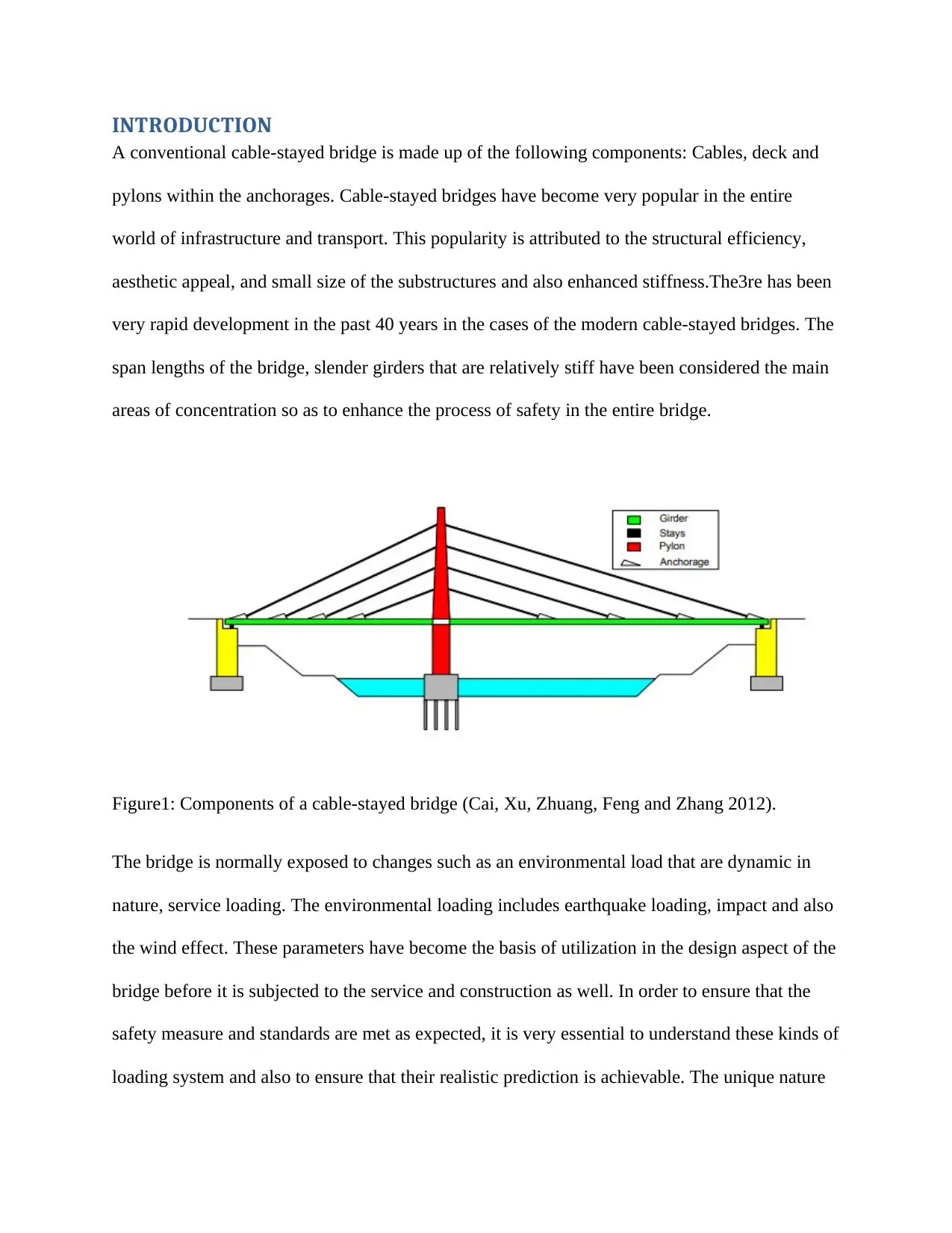
A conventional cable-stayed bridge is made up of the following components: Cables, deck and
pylons within the anchorages. Cable-stayed bridges have become very popular in the entire
world of infrastructure and transport. This popularity is attributed to the structural efficiency,
aesthetic appeal, and small size of the substructures and also enhanced stiffness.The3re has been
very rapid development in the past 40 years in the cases of the modern cable-stayed bridges. The
span lengths of the bridge, slender girders that are relatively stiff have been considered the main
areas of concentration so as to enhance the process of safety in the entire bridge.
Figure1: Components of a cable-stayed bridge (Cai, Xu, Zhuang, Feng and Zhang 2012).
The bridge is normally exposed to changes such as an environmental load that are dynamic in
nature, service loading. The environmental loading includes earthquake loading, impact and also
the wind effect. These parameters have become the basis of utilization in the design aspect of the
bridge before it is subjected to the service and construction as well. In order to ensure that the
safety measure and standards are met as expected, it is very essential to understand these kinds of
loading system and also to ensure that their realistic prediction is achievable. The unique nature
of the bridge makes the length of the span very long besides adding beauty to the environment.
However, here is an addition of difficulties in the analysis of the bridge as accurately required.
The cable-stayed bridges and the long span are known to constitute the structural complex
system of the bridge that possesses very high geometric nonlinearity. In addition to the
highlighted effects, the original equilibrium configuration that is placed under the dead loads has
very significant effects on the structural properties of the cable-stayed bridges.
The long span cable-stayed bridge is known to have nonlinear properties when subjected to any
other form of loading conditions. The sources that are normally considered nonlinear originate
from the following:
I. The inclined stay cables have the sag effects
II. The towers and the girders are affected by the combined axial loading and also bending
moments
III. There are very huge effects of the displacement
IV. The stress-strain of the materials used may be sometimes are nonlinear.
The method of the discretized finite element normally provides very convenient and also the
reliable principle of the structural continua. This method is particularly effective when using the
digital analysis of the computer. The nonlinear analysis of the modern cable-stayed bridges is
normally achieved using the finite deformation theory. This particular theory uses the discrete
finite element model as its most recognized tool.
It is important to note that it has never been an easy task in the establishment of reliable and also
real finite model element of such kind of complicated structures. This particular process will
entirely need the bridge field test of the obtained results and the other future analysis. The field
test results are used in the calibration and in the entire update of the initial finite element model.
For the cases of the long span bridges, it is very important to ensure that there is an establishment
of the analytical dynamic properties from the finite element used in predicting other properties.
This also includes the measured dynamic properties from the field testing.
Several research works have been carried out on the properties of the cable-stayed bridges that
are considered dynamic to some extent. In such research works, the obvious structural response
of the bridge due to the wind effect and also loading from the traffic has been identified as the
key factors that affect the design(Cai, Xu, Zhuang, Feng and Zhang 2012). These two parameters
are known to have a great effect on the dynamic characteristics of the bridge. The structural
model that is updating the changes in the form of calibration has been considered the latest
technology to be used. This particular technology ensures that there is the provision of the
worldwide way of evaluating the state of the structures.
In regard to these characteristics, there has been detailed literature review by other scholars as
well. The application of this technology has been very diverse and also very much scattered.
Upon the calibration of the finite element model as per the parameters of the dynamic loading,
this particular model can then be used as the standard tool for aerodynamic predictions. Also, the
calibrated finite element model can as well be used as the common baseline for the assessment of
the health of the structure of the bridge in the upcoming times. The current work pays more
attention to comprehensive research that allows for the applications of the three-dimensional
finite element analysis of the model. This model has been recommended for the use in the
Secure Best Marks with AI Grader
Need help grading? Try our AI Grader for instant feedback on your assignments.
analysis of the Owensboro cable-stayed bridge. Therefore the three-dimensional analysis models
have been created in the solid work software.
This is considered one of the general purpose commercial finite software. In this analysis, all the
geometrically sources that are considered nonlinear are factored in.These nonlinear sources
include cable sags, axial forces, large deflections and also bearing moments interactions. In order
to account for the effects of the dead loads, the initial equilibrium is achieved. The free vibration
field test is then used in the furthered update of the finite element analysis model. The analytical
model that is also calibrated using the results from the experiment is used to assist in the study of
the dynamic responses of the bridge as it is subjected to various changes in the parameter. This
effect may extend to the static changes of the parameters as well.
The model of the finite element that is already calibrated can be used as the baseline in the
analysis of the structures and therefore assist in the monitoring of the Owensboro cable-stayed
bridge. The testing of the cable, as well as the modeling for the identified bridge, has been
performed separately. The outcome of this particular study can be used in the provision of
important information and also the relevant data for the development of a design that is more and
more refined. The analysis tool for the future analysis of the bridge becomes readily available.
Description of the bridge
The Owensboro cable-stayed bridge connects the Kentucky and Rockport Indiana over the Ohio
River as indicated in the figure below. This has been regarded as one of the longest cable-stayed
spans over the United States waterway system that is found inland. The main component of the
bridge has a total length of over 4505ft. This extreme parameter includes span that is over
1200ft. The other two sides span are considered to be 500ft. The approach of Kentucky is almost
1345 ft. long. The approach for Indiana is at 960 ft. long. The entire width of the structure is 67
ft. from one parapet to the next adjacent parapet. The other parts included within these
components extend to four 12 foot traffic lanes and also four-foot shoulders. The main
superstructure of the stay-cable bridge is made up of the concrete deck which normally draws its
support from other two main 12-foot deep plate that is made from the steel component of girders.
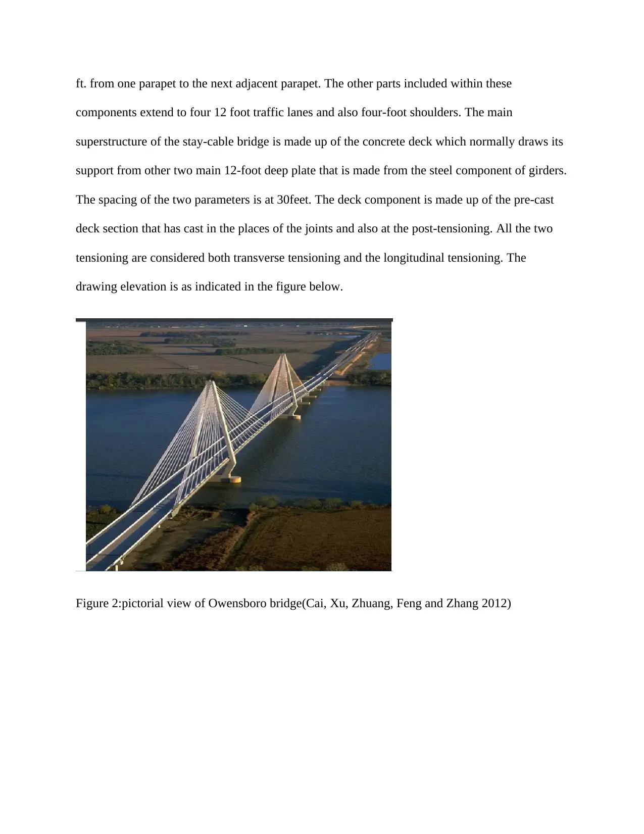
The spacing of the two parameters is at 30feet. The deck component is made up of the pre-cast
deck section that has cast in the places of the joints and also at the post-tensioning. All the two
tensioning are considered both transverse tensioning and the longitudinal tensioning. The
drawing elevation is as indicated in the figure below.
Figure 2:pictorial view of Owensboro bridge(Cai, Xu, Zhuang, Feng and Zhang 2012)
components extend to four 12 foot traffic lanes and also four-foot shoulders. The main
superstructure of the stay-cable bridge is made up of the concrete deck which normally draws its
support from other two main 12-foot deep plate that is made from the steel component of girders.
The spacing of the two parameters is at 30feet. The deck component is made up of the pre-cast
deck section that has cast in the places of the joints and also at the post-tensioning. All the two
tensioning are considered both transverse tensioning and the longitudinal tensioning. The
drawing elevation is as indicated in the figure below.
Figure 2:pictorial view of Owensboro bridge(Cai, Xu, Zhuang, Feng and Zhang 2012)
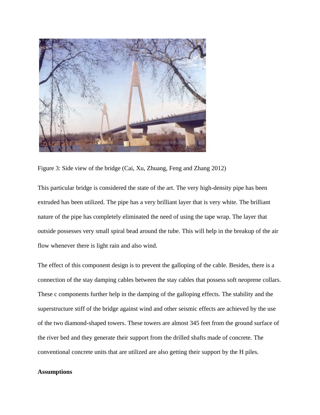
Figure 3: Side view of the bridge (Cai, Xu, Zhuang, Feng and Zhang 2012)
This particular bridge is considered the state of the art. The very high-density pipe has been
extruded has been utilized. The pipe has a very brilliant layer that is very white. The brilliant
nature of the pipe has completely eliminated the need of using the tape wrap. The layer that
outside possesses very small spiral bead around the tube. This will help in the breakup of the air
flow whenever there is light rain and also wind.
The effect of this component design is to prevent the galloping of the cable. Besides, there is a
connection of the stay damping cables between the stay cables that possess soft neoprene collars.
These c components further help in the damping of the galloping effects. The stability and the
superstructure stiff of the bridge against wind and other seismic effects are achieved by the use
of the two diamond-shaped towers. These towers are almost 345 feet from the ground surface of
the river bed and they generate their support from the drilled shafts made of concrete. The
conventional concrete units that are utilized are also getting their support by the H piles.
Assumptions
Paraphrase This Document
Need a fresh take? Get an instant paraphrase of this document with our AI Paraphraser
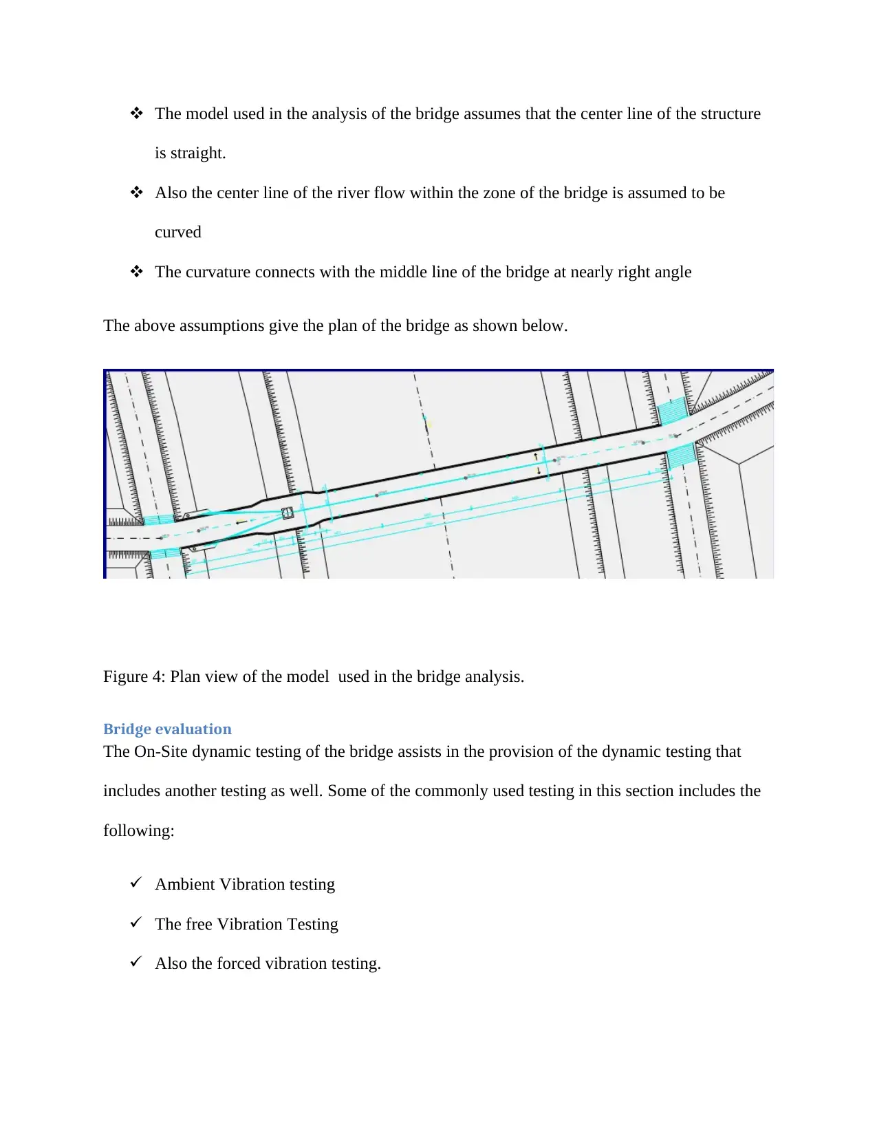
The model used in the analysis of the bridge assumes that the center line of the structure
is straight.
Also the center line of the river flow within the zone of the bridge is assumed to be
curved
The curvature connects with the middle line of the bridge at nearly right angle
The above assumptions give the plan of the bridge as shown below.
Figure 4: Plan view of the model used in the bridge analysis.
Bridge evaluation
The On-Site dynamic testing of the bridge assists in the provision of the dynamic testing that
includes another testing as well. Some of the commonly used testing in this section includes the
following:
Ambient Vibration testing
The free Vibration Testing
Also the forced vibration testing.
In the cases of the free vibration testing as well as the forced vibration testing, the cable-stayed
structure is subject to artificial forces from the shakers, test vehicles or the drop weights. The
condition of the free vibration is generated when a load is suddenly dropped on the structure.
This particular method of the test has got some elements of disadvantages since the traffic must
be shut down for a considerable amount of time. This will definitely be a very serious problem
for those vehicles that carry a large amount of traffic of vehicles.
The ambient vibration testing, on the other hand, does not affect the traffic on the bridge
considering that it uses the already present traffic of vehicles and the original force from the
wind effects to initiate the loading for the excitement of the bridge. Since this method does not
need any extra equipment for the experiment, it is normally considered cheaper as compared to
the forced vibration. However, this method will need very long records of measurement response
and the measured data need to be more stochastic. Finally, the results that are obtained here may
be very less reliable as compared to the results that would otherwise be generated from the
forced vibration.
In this particular case, the Owensboro cable-stayed bridge had its onsite dynamic testing
performed through free vibration testing. The dynamic p[properties of the Owensboro cable-
stayed bridge were then obtained from the peak of the average normalized power spectral
densities. The properties of the vibrations are later used as the basis for providing an update of
the finite elect bridge model.
Calibration and Finite Element Modeling
The prediction of the dynamic and static structural characteristics of the cable-stayed bridge has
been made simpler with the modern commercial finite element programs. The discretized model
of finite element provides a very convenient and also idealization that is reliable. The other
factors that have led to rapid developments include the matrix analysis of the computer, rapid
computer developments, and the deformation theory of the finite modeling of elements. These
developments have been considered the most powerful tools for the analysis of the cable-stayed
bridge. The main advantage of the finite element analysis is that the complexities that are
available within the structural components can be effectively considered. The effects of other
nonlinear cable-stayed bridge sources that include the cable sags, the bending moments and other
large deflections can be sorted out properly using the deformation theory. The other advantage of
the FEA is the possibility of the in-depth dynamic analysis.
The use of the solid works in the design of the component allowed for the complete three-
dimensional analysis of the model. The program has been selected because of the ability to allow
for the analysis of the stress stiffening and also the process of pre-stressed analysis of the model.
The finite element model of the bridge is made up of the two types of the element. The 3-D
elastic beam component and also the 3-D tension only truss components. The chosen model has
over 668 nodes and 1087 FEA that allows for over 3960 digress of freedom.
In the process of the design of the cable-stayed bridges, most of the load on the bridge is
contributed by the dead load. The static analysis of FEA is used to account for such dead loads
before the process of the dynamic analysis is carried out. The main aim of the process of the
dynamic analysis is to achieve the configuration of the deformed equilibrium of the load,
especially where the structural members are pre-stressed. The onsite testing is used in the
determination of the initial tension in the bridge.
This kind of bridge is normally regarded as a highly pre-stressed structure or component. The
model analysis is done starting from the deformed equilibrium configuration. The modal analysis
Secure Best Marks with AI Grader
Need help grading? Try our AI Grader for instant feedback on your assignments.

will, therefore, include the load effect to the stiffness and this takes place when the pre-stress
forces are present in the cable. The analysis of the modal is basically a pre-stressed process that
allows for the generation of the frequencies and therefore shapes of the modes can be effectively
calculated. A comprehensive understanding of the dynamic properties of the bridge constitutes
the coupled mode. In order to perform the parametric studies, the following parameters can be
put into consideration. The cable stiffness, the self-weight of the deck and also the edge girder.
The establishment of the initial finite element analysis to be used in the structural evaluation has
been relatively difficult as a result of the deviation of the original structure in the geometry of the
material. The original finite element model has had its update on the end of calibration based on
the testing results from the field. This assisted in the approximation of the present state of the
bridge. The updating process of the finite element is performed until the generated frequencies
match the values generated from the field testing. The finite element model that has been updated
is used as the baseline for the evaluation of the bridge in the future.
Modeling and testing of the cable
Different consideration of the response of the cable is normally motivated by the occurrence of
the wind-induced vibrations of the structure. This particular effect has been observed and
undergone documentations over a long period of the timeout of the bridges that were under the
study had their failure attributed to the rain wind vibrations. There has been a continuous study
on the factors that affect the wind-induced stay cable vibrations with the main aim of producing
the best design approach for further mitigation and prevention. The Owensboro Bridge is made
up of over ninety-six cables that are just unique and also flexible. The dynamic properties of the
bridge depending on the tension, possible temperatures, and the material characteristics. In order
to bring the bridge to the deck into the proper line of the alignment, the construction of the
sections has been made to meet at the Centre. The cable design was adjusted to ensure that there
was a smooth profile on the vertical deck. The modeling and the testing of the bridge were
conducted in two field tests. The very first test was just before the bridge opened by the activities
of the excitation by the trucks. In the second test, there was the use of the ambient process of
excitation. This included the typical effects of wind and traffic as well. The signal processes sing
analysis of the recorded acceleration was used to establish the fundamental frequencies within
the cable. The FEA models were developed for use in all the cables that compared the results and
did the necessary corrections.
OBJECTIVES
The main objective of this particular project is to design and analyze the stay cable bridge
of Owensboro bridge.
To establish the cable resilience after one of the cables is lost
To understand further the dynamic response and also the structural behaviour of the
cable-stayed bridge after the loss of the cable.
The scope of the work
The main aim of this investigation is to perform an evaluation of the structural analysis of the
dynamic characteristics of the Owensboro cable-stayed bridge alongside the establishment of the
baseline line model of the structure. The evaluation process of the dynamic based structural will
be used in the entire process. In order to ensure that the above objective is accomplished, the task
has been subdivided into five main categories.
Modal analysis and finite element modeling
Extraction of the dynamic characteristics from on-site testing of the free vibrations
Having field tests of the stay cables and the finite element for the purposes of the
modeling process
Understanding the structural properties when subjected to loading forms and other
relevant environmental dynamic loading.
Calibration of the FEA model using the results from the field test.
FLOW OF TRAFFIC ENVIRONMENTAL CONDITION OF THE AREA, SOIL
CONDITION SUITABLE FOR THE BRIDGE.
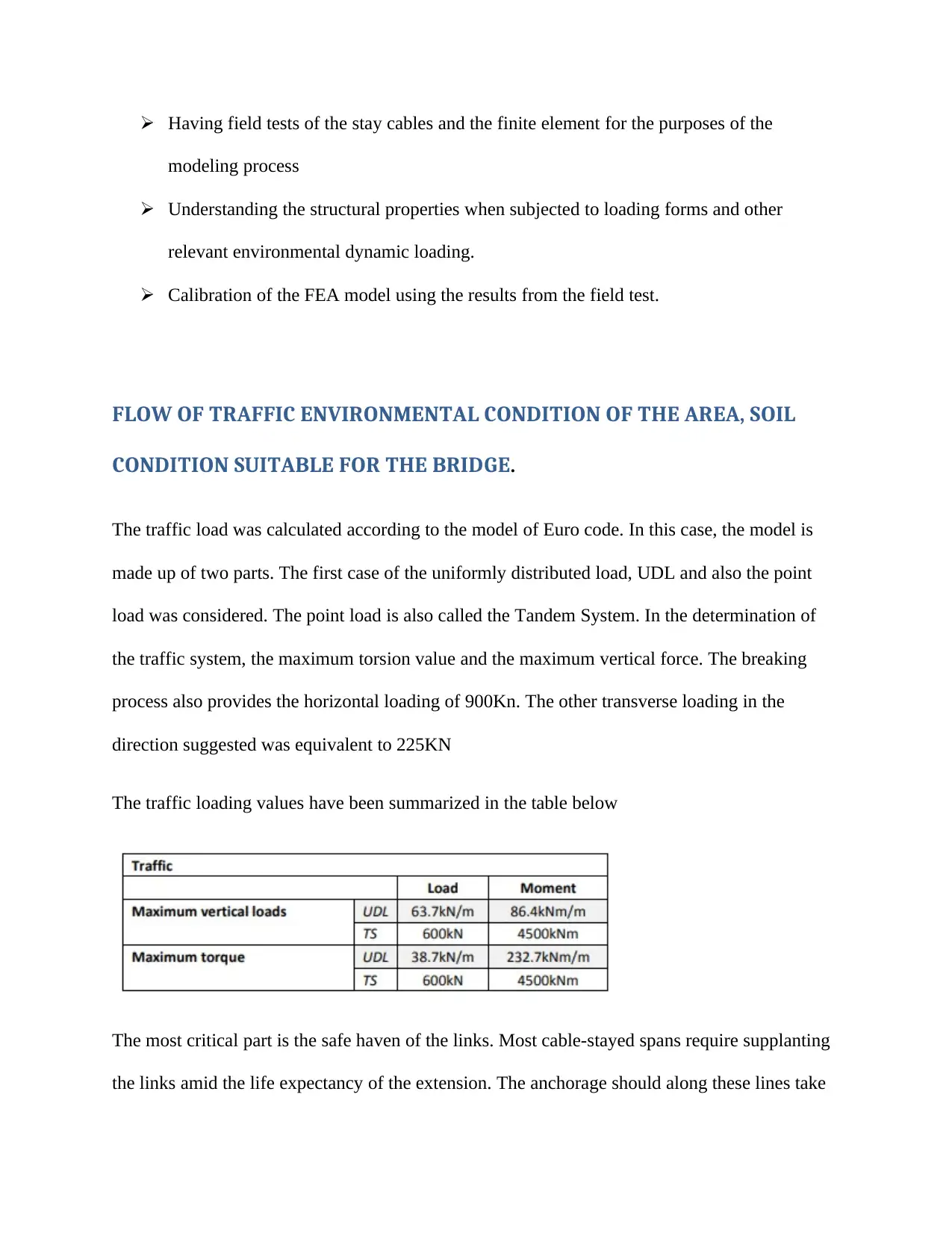
The traffic load was calculated according to the model of Euro code. In this case, the model is
made up of two parts. The first case of the uniformly distributed load, UDL and also the point
load was considered. The point load is also called the Tandem System. In the determination of
the traffic system, the maximum torsion value and the maximum vertical force. The breaking
process also provides the horizontal loading of 900Kn. The other transverse loading in the
direction suggested was equivalent to 225KN
The traffic loading values have been summarized in the table below
The most critical part is the safe haven of the links. Most cable-stayed spans require supplanting
the links amid the life expectancy of the extension. The anchorage should along these lines take
modeling process
Understanding the structural properties when subjected to loading forms and other
relevant environmental dynamic loading.
Calibration of the FEA model using the results from the field test.
FLOW OF TRAFFIC ENVIRONMENTAL CONDITION OF THE AREA, SOIL
CONDITION SUITABLE FOR THE BRIDGE.
The traffic load was calculated according to the model of Euro code. In this case, the model is
made up of two parts. The first case of the uniformly distributed load, UDL and also the point
load was considered. The point load is also called the Tandem System. In the determination of
the traffic system, the maximum torsion value and the maximum vertical force. The breaking
process also provides the horizontal loading of 900Kn. The other transverse loading in the
direction suggested was equivalent to 225KN
The traffic loading values have been summarized in the table below
The most critical part is the safe haven of the links. Most cable-stayed spans require supplanting
the links amid the life expectancy of the extension. The anchorage should along these lines take
Paraphrase This Document
Need a fresh take? Get an instant paraphrase of this document with our AI Paraphraser
into consideration substitution and alterations. There are reinforced and unbounded anchorages.
The strands are settled by removable wedges in unbounded safe havens, and grouted with filling
in limited harbors. The favorable position with unbounded harbor is that the link or strand can be
all the more effectively supplanted. In any case, a wedge is a sensitive auxiliary component and
is defenseless to development deviation which must be considered in the structure. The filling,
which disseminates the neighborhood worries in each wire/strand in limited moorings, enhance
the safe havens quality for weakness and over-burdening.
An achievable mooring set at the deck structure, displayed in the figure below comprises of a
steel pipe connected to the deck. It can either be welded or grouted to the edge light emission
deck contingent upon the material of the deck. The grapple is frequently settled in the right edge
of the tendency at the deck and customizable at the arch grapple. The steel pipe proceeds around
1.2m over the street level for security. At the best is a delicate neoprene cushion pursued by a
seal of an elastic sleeve. The delicate best stops flexural developments of the link and damps
motions. There are three distinct ideas of tying down the links at the arch; saddle, befuddling or
deadlock. The seat works like a suspension connect bearing, it is costly to introduce and hard to
substitute and not prescribed for link stayed spans (Larsen and Larose 2015).
The structured establishment will be put in the focal piece of the Owensboro Bridge. The island
is associated with the stream banks and terrain through two Red locks, which are found ca. 70 m
north and through the chronicled weir, found ca. 110 m south-west. The zone assigned for the
foundation is 67.4 m x 28.0 m. The territory under establishment is essentially level with the
mean height of 112.8 ma.s.l. From the geomorphological purpose of seeing it is situated in
Wrocław-Magdeburg ice-minor valley (Ohio River Valley), 10 km wide and loaded up with
Pleistocene and Holocene waterway dregs with a few patios at different levels. The surface layer
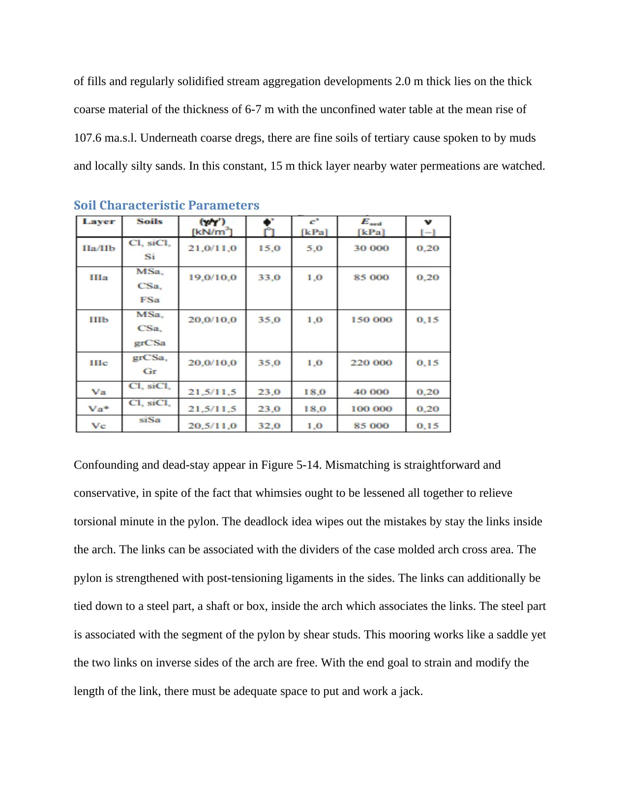
of fills and regularly solidified stream aggregation developments 2.0 m thick lies on the thick
coarse material of the thickness of 6-7 m with the unconfined water table at the mean rise of
107.6 ma.s.l. Underneath coarse dregs, there are fine soils of tertiary cause spoken to by muds
and locally silty sands. In this constant, 15 m thick layer nearby water permeations are watched.
Soil Characteristic Parameters
Confounding and dead-stay appear in Figure 5-14. Mismatching is straightforward and
conservative, in spite of the fact that whimsies ought to be lessened all together to relieve
torsional minute in the pylon. The deadlock idea wipes out the mistakes by stay the links inside
the arch. The links can be associated with the dividers of the case molded arch cross area. The
pylon is strengthened with post-tensioning ligaments in the sides. The links can additionally be
tied down to a steel part, a shaft or box, inside the arch which associates the links. The steel part
is associated with the segment of the pylon by shear studs. This mooring works like a saddle yet
the two links on inverse sides of the arch are free. With the end goal to strain and modify the
length of the link, there must be adequate space to put and work a jack.
Four choices with respect to the establishment of the arch were being viewed as i.e.: the shallow
establishment in the layer of thick coarse soils, establishment on the wall dividers, and
establishment on the square made of stream grouting segments and establishment on huge
breadth exhausted heaps. At long last, the most recent idea has been expected for structure. Also,
exhausted heaps were reinforced by the infusion under the heap base. Such an arrangement was
found to be ideal mechanically in the dirt conditions. The idea of the shallow foundation was
dismissed because of little thickness of coarse material beneath the establishment level. On
account of wall dividers, the issue may be low shaft bearing limit. The establishment on the
square made of infusion segments has been dismissed because of substantial volume and mass of
the square.
DESIGN ANALYSIS
There have been very many reports regarding the occurrence of wind-induced vibrations of the
cable-stayed bridge in various parts of the world. Some of the most recently identified include
the vibrations of the rain wind that has been occurring on the other Ohio River crossing. The
previous testing of the cable-stayed bridge has indicated persistence in the rain-wind response of
the used cables. In the Maysville design, there was a use of the close ties that were considered
very effective in limiting the amplitude of the responses from the wind-induced.
Secure Best Marks with AI Grader
Need help grading? Try our AI Grader for instant feedback on your assignments.
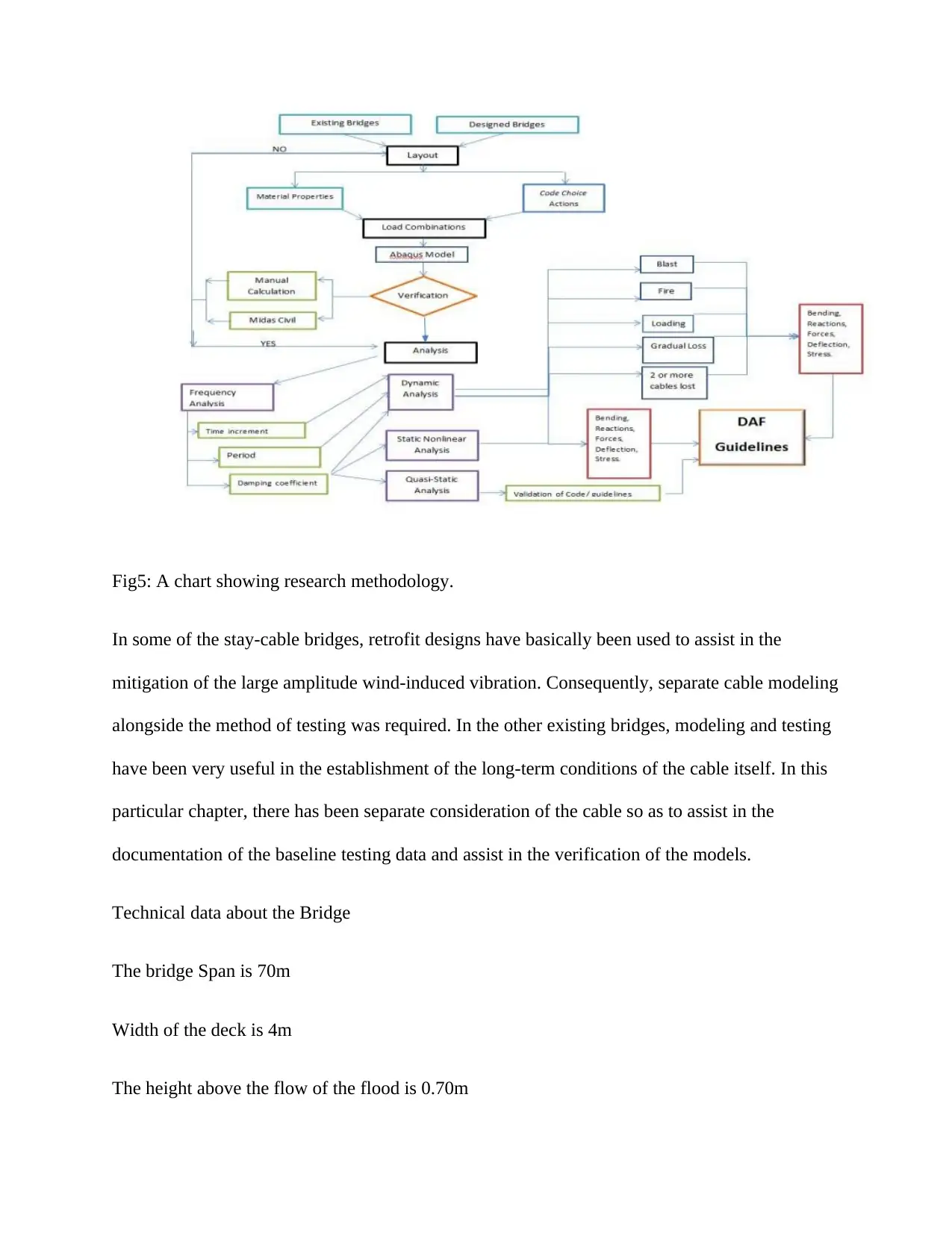
Fig5: A chart showing research methodology.
In some of the stay-cable bridges, retrofit designs have basically been used to assist in the
mitigation of the large amplitude wind-induced vibration. Consequently, separate cable modeling
alongside the method of testing was required. In the other existing bridges, modeling and testing
have been very useful in the establishment of the long-term conditions of the cable itself. In this
particular chapter, there has been separate consideration of the cable so as to assist in the
documentation of the baseline testing data and assist in the verification of the models.
Technical data about the Bridge
The bridge Span is 70m
Width of the deck is 4m
The height above the flow of the flood is 0.70m
Material used for the deck included pre-stressed reinforced concrete.
Bridge structure description
Superstructure: girder, stay cable and pylon
Bridge analysis in terms of the structure
Dynamic analysis
Static analysis
Other details included in the design concept include;
Plans of reinforcement
Main girder assembly.
General information about the bridge model
Assumptions
The model used in the analysis of the bridge assumed the following parameters
As per the given boundary conditions as well as the allowable concept of the precast super
structure, the design of the bridge was as cable stayed beam. The spans that were included were
two, 14.0 plus 56.0=70m
The superstructure of the bridge was made up of pre-stressed concrete deck, one pylon and
3+2x3 cable-stays on the left side of the plan of the river.
The road level of the bridge zone has been set as low as possible to ensure that the conditions set
are respected so as to allow for the opening of the flow of the flood. The solution of the design
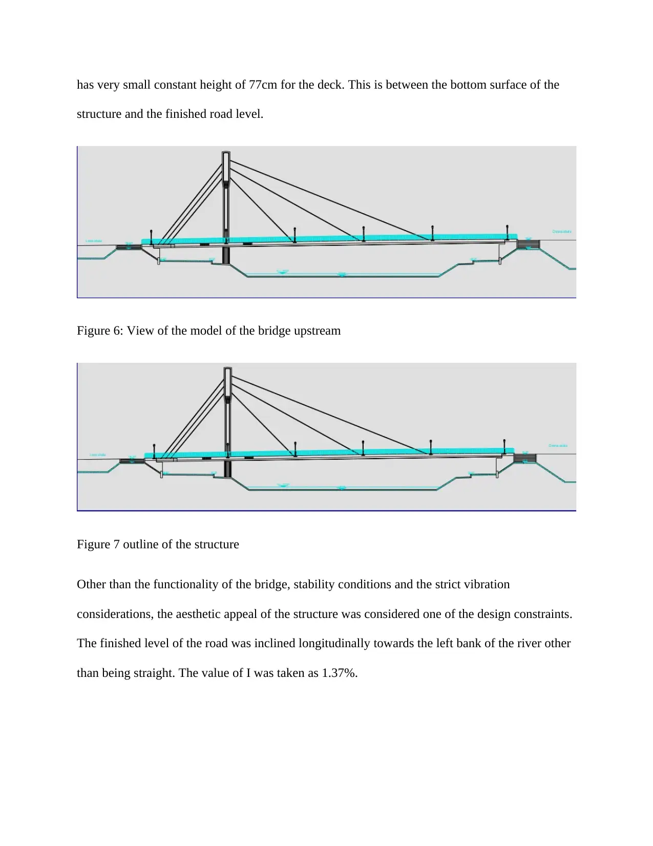
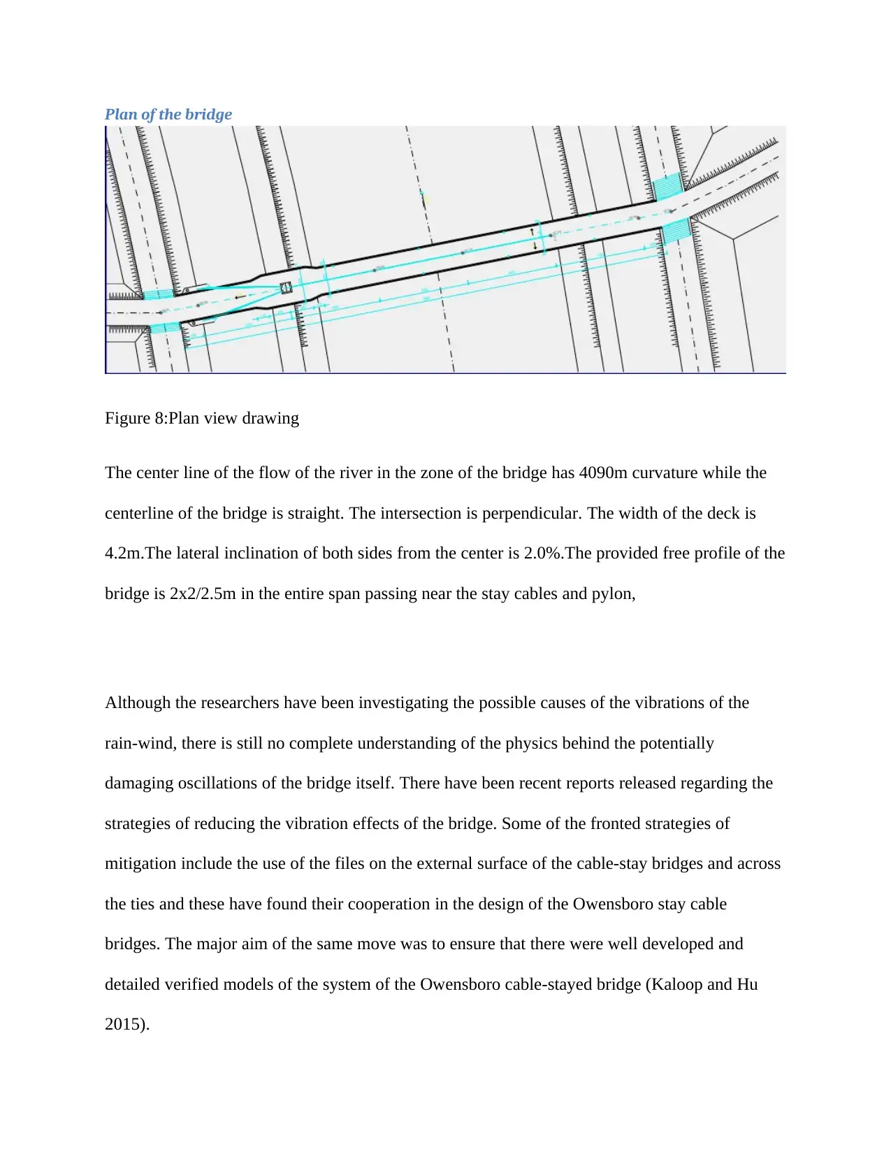
has very small constant height of 77cm for the deck. This is between the bottom surface of the
structure and the finished road level.
Figure 6: View of the model of the bridge upstream
Figure 7 outline of the structure
Other than the functionality of the bridge, stability conditions and the strict vibration
considerations, the aesthetic appeal of the structure was considered one of the design constraints.
The finished level of the road was inclined longitudinally towards the left bank of the river other
than being straight. The value of I was taken as 1.37%.
Paraphrase This Document
Need a fresh take? Get an instant paraphrase of this document with our AI Paraphraser
Plan of the bridge
Figure 8:Plan view drawing
The center line of the flow of the river in the zone of the bridge has 4090m curvature while the
centerline of the bridge is straight. The intersection is perpendicular. The width of the deck is
4.2m.The lateral inclination of both sides from the center is 2.0%.The provided free profile of the
bridge is 2x2/2.5m in the entire span passing near the stay cables and pylon,
Although the researchers have been investigating the possible causes of the vibrations of the
rain-wind, there is still no complete understanding of the physics behind the potentially
damaging oscillations of the bridge itself. There have been recent reports released regarding the
strategies of reducing the vibration effects of the bridge. Some of the fronted strategies of
mitigation include the use of the files on the external surface of the cable-stay bridges and across
the ties and these have found their cooperation in the design of the Owensboro stay cable
bridges. The major aim of the same move was to ensure that there were well developed and
detailed verified models of the system of the Owensboro cable-stayed bridge (Kaloop and Hu
2015).

The other previous testing on other bridges like the Maysville indicated the accuracy and the
utility of using the short time record of measuring the acceleration of the cables so as to
determine the fundamentals of the frequencies in the model verification. The comparison of the
motions was enabled in the simultaneous recording of the acceleration experienced on the deck
anchor and the cable itself. The same procedures have been used in this particular effort of the
Owensboro Bridge to ensure that the dynamic responses of the deck anchors and the cables are
properly measured. The other key objectives remain the observation of the cables alongside their
analysis within the context of the reports that was recently released.
It very much important to note that the frequencies identified for the case of the cables will
always differ from one of the field tests to the other field test. In the case of Maysville for
example; there are differences on the length of the cable that was as a result of the effects of the
temperatures and the application mode. The cable modeling of the Owensboro Bridge did not put
into consideration the aim to ensure examination of the trends with the temperatures.
The Owensboro Bridge is a unique flexible structure that has characteristics of the dynamic
responses which entirely depends on the properties of the material used, the possible variations
in the temperature and finally tension on the bridge itself. The cables that were used in the design
have been effectively numbered. The cable design tensions were adjusted from the one that was
listed in the original plan so as to bring the bridge deck into the proper alignment set on the side
to side. This was also necessary to ensure that the vertical deck profile was made smooth as well.
There was significant variation in the cable tension from an average of 24%. Some of the tension
of the bridge cables decreased by up to 72%. The changes of the dead load were presented
graphically. It is also important to note that the largest tension effects occurred on the longest
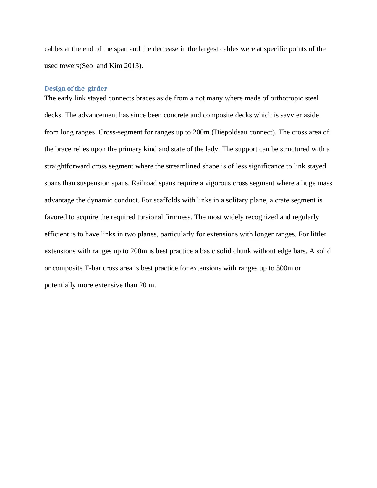
cables at the end of the span and the decrease in the largest cables were at specific points of the
used towers(Seo and Kim 2013).
Design of the girder
The early link stayed connects braces aside from a not many where made of orthotropic steel
decks. The advancement has since been concrete and composite decks which is savvier aside
from long ranges. Cross-segment for ranges up to 200m (Diepoldsau connect). The cross area of
the brace relies upon the primary kind and state of the lady. The support can be structured with a
straightforward cross segment where the streamlined shape is of less significance to link stayed
spans than suspension spans. Railroad spans require a vigorous cross segment where a huge mass
advantage the dynamic conduct. For scaffolds with links in a solitary plane, a crate segment is
favored to acquire the required torsional firmness. The most widely recognized and regularly
efficient is to have links in two planes, particularly for extensions with longer ranges. For littler
extensions with ranges up to 200m is best practice a basic solid chunk without edge bars. A solid
or composite T-bar cross area is best practice for extensions with ranges up to 500m or
potentially more extensive than 20 m.
Secure Best Marks with AI Grader
Need help grading? Try our AI Grader for instant feedback on your assignments.
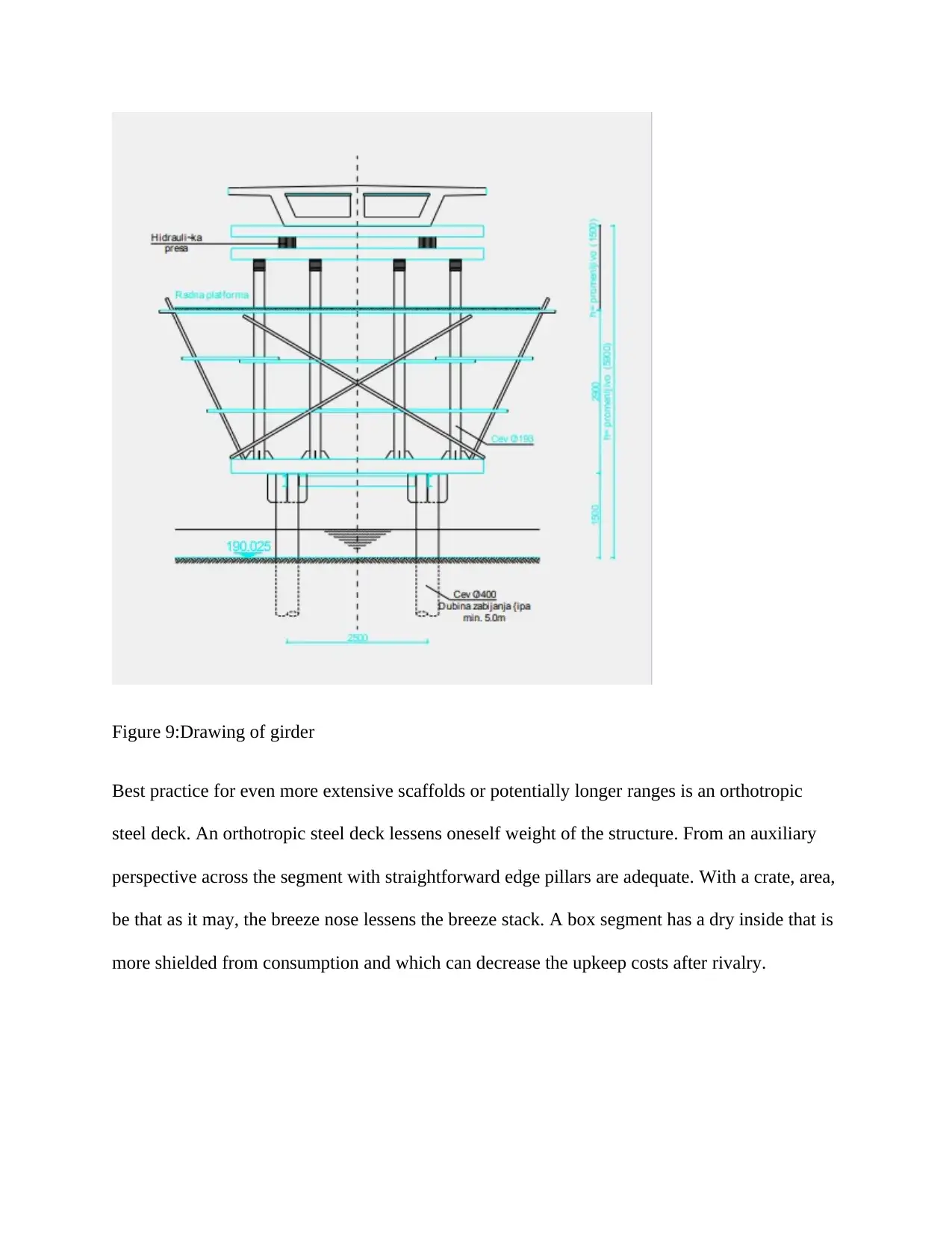
Figure 9:Drawing of girder
Best practice for even more extensive scaffolds or potentially longer ranges is an orthotropic
steel deck. An orthotropic steel deck lessens oneself weight of the structure. From an auxiliary
perspective across the segment with straightforward edge pillars are adequate. With a crate, area,
be that as it may, the breeze nose lessens the breeze stack. A box segment has a dry inside that is
more shielded from consumption and which can decrease the upkeep costs after rivalry.
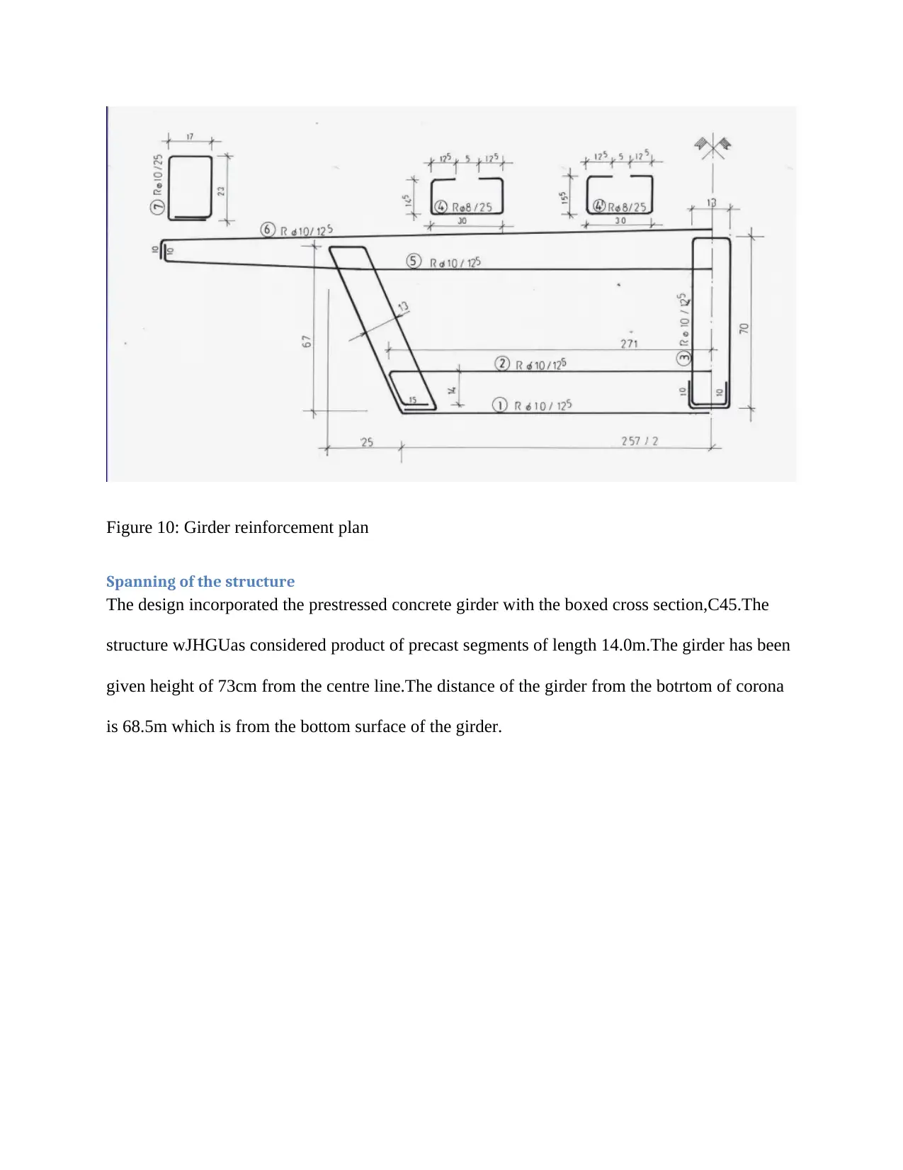
Figure 10: Girder reinforcement plan
Spanning of the structure
The design incorporated the prestressed concrete girder with the boxed cross section,C45.The
structure wJHGUas considered product of precast segments of length 14.0m.The girder has been
given height of 73cm from the centre line.The distance of the girder from the botrtom of corona
is 68.5m which is from the bottom surface of the girder.
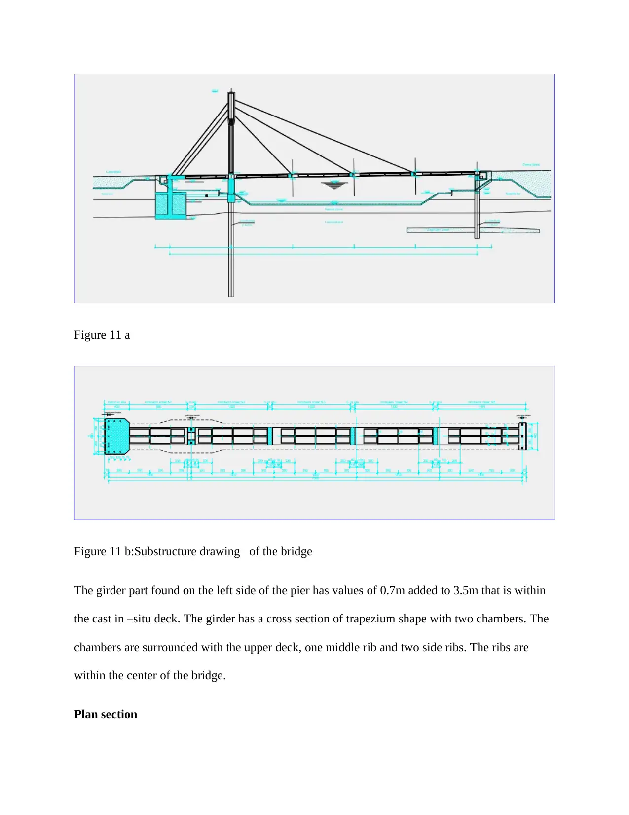
Figure 11 a
Figure 11 b:Substructure drawing of the bridge
The girder part found on the left side of the pier has values of 0.7m added to 3.5m that is within
the cast in –situ deck. The girder has a cross section of trapezium shape with two chambers. The
chambers are surrounded with the upper deck, one middle rib and two side ribs. The ribs are
within the center of the bridge.
Plan section
Paraphrase This Document
Need a fresh take? Get an instant paraphrase of this document with our AI Paraphraser
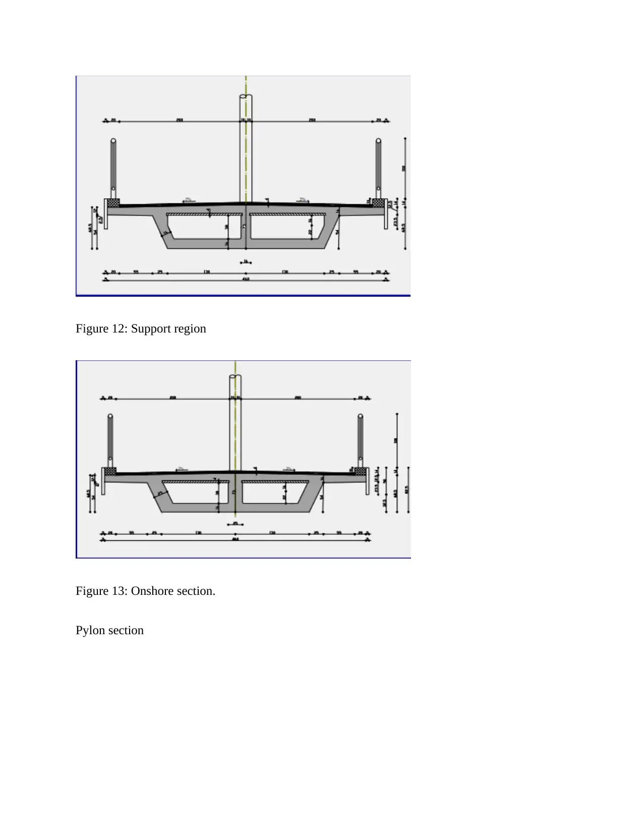
Figure 12: Support region
Figure 13: Onshore section.
Pylon section
Figure 13: Onshore section.
Pylon section
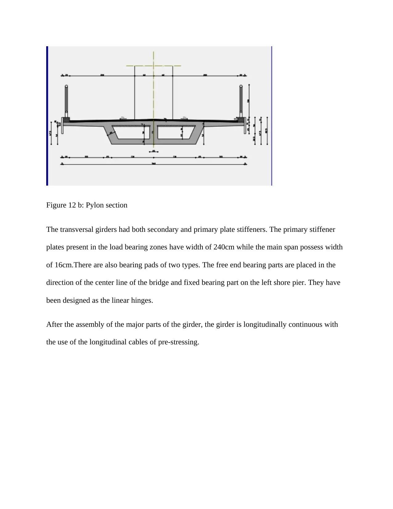
Figure 12 b: Pylon section
The transversal girders had both secondary and primary plate stiffeners. The primary stiffener
plates present in the load bearing zones have width of 240cm while the main span possess width
of 16cm.There are also bearing pads of two types. The free end bearing parts are placed in the
direction of the center line of the bridge and fixed bearing part on the left shore pier. They have
been designed as the linear hinges.
After the assembly of the major parts of the girder, the girder is longitudinally continuous with
the use of the longitudinal cables of pre-stressing.
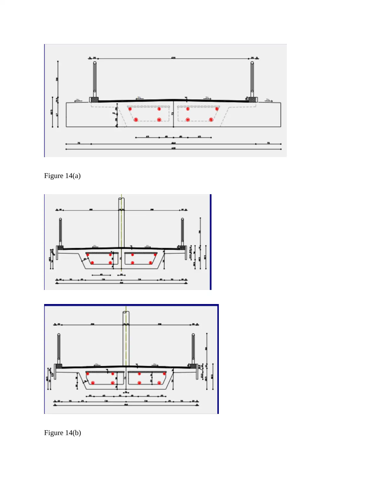
Figure 14(a)
Figure 14(b)
Figure 14(b)
Secure Best Marks with AI Grader
Need help grading? Try our AI Grader for instant feedback on your assignments.
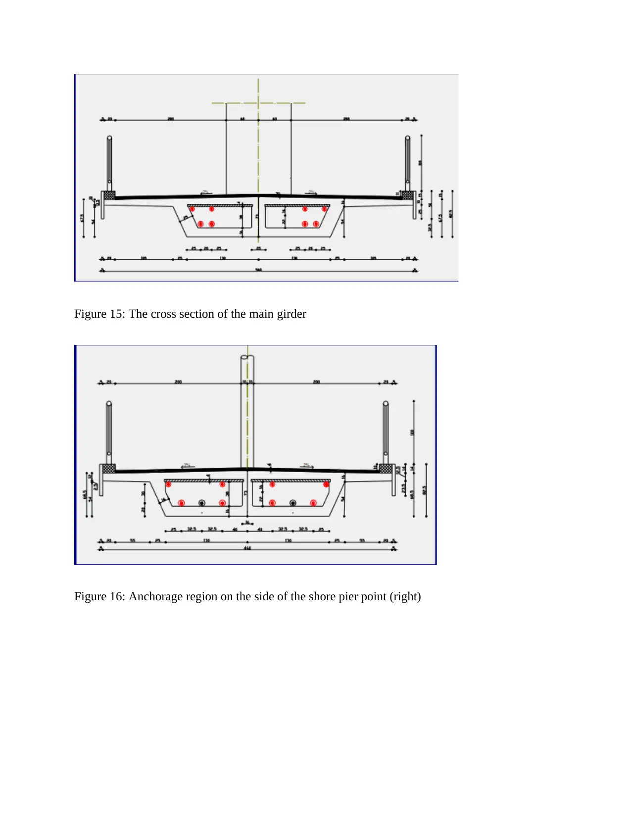
Figure 15: The cross section of the main girder
Figure 16: Anchorage region on the side of the shore pier point (right)
Figure 16: Anchorage region on the side of the shore pier point (right)
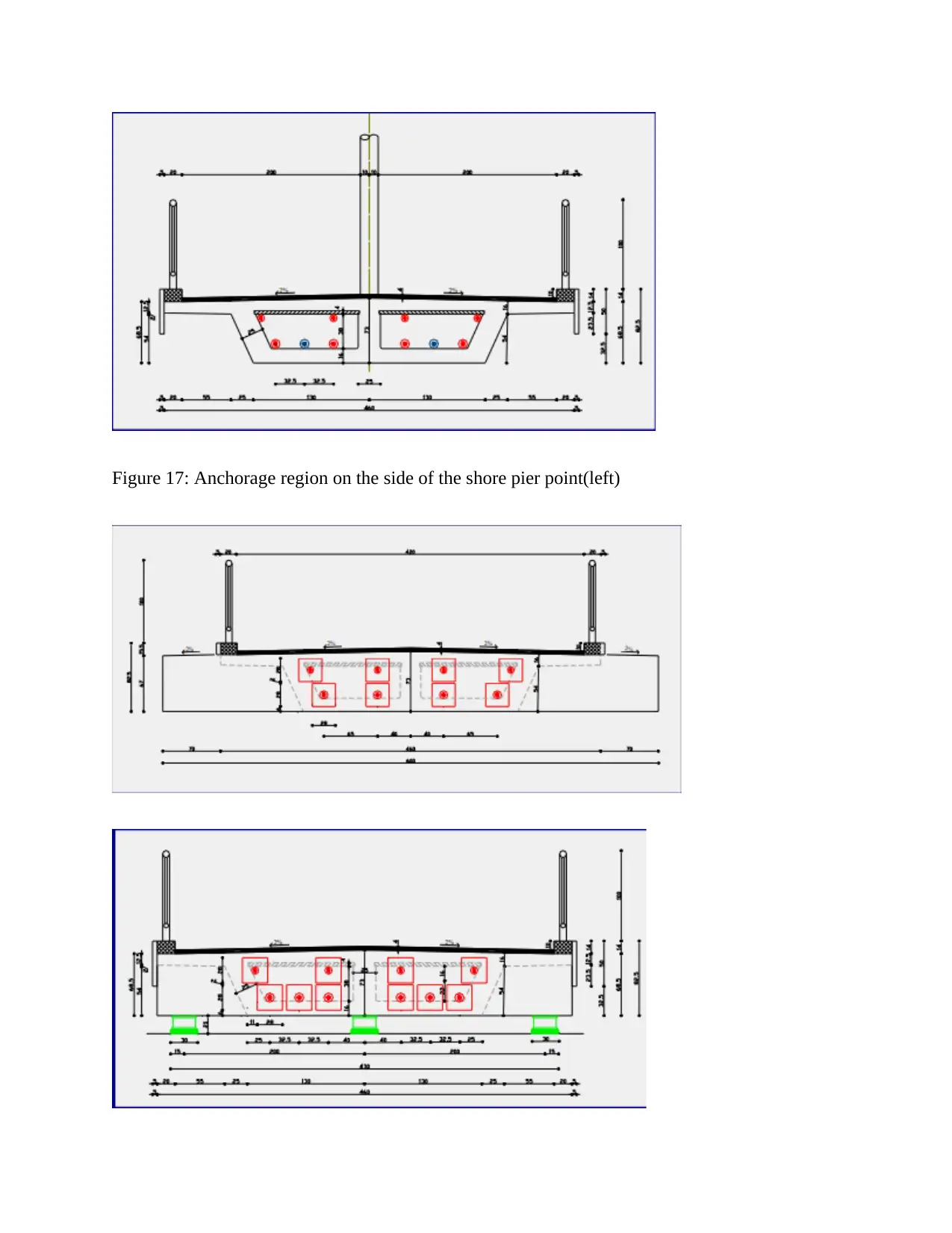
Figure 17: Anchorage region on the side of the shore pier point(left)
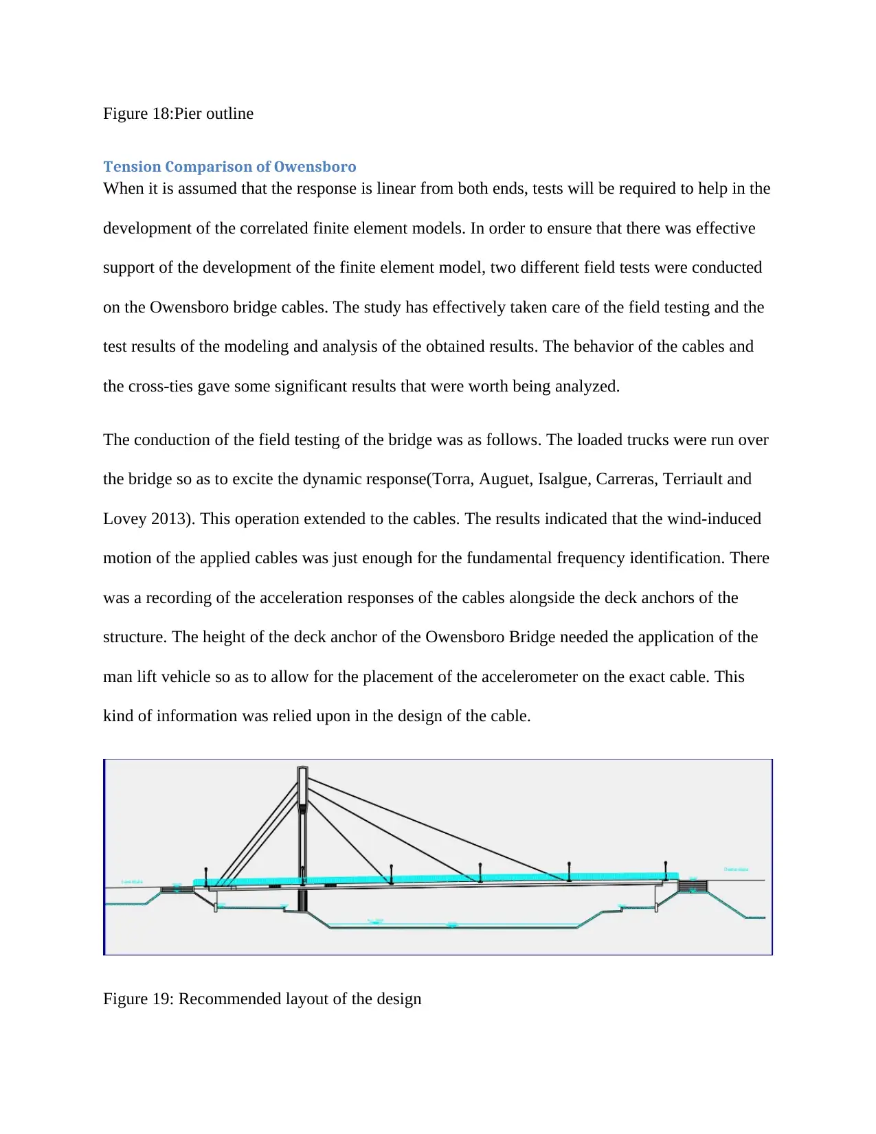
Figure 18:Pier outline
Tension Comparison of Owensboro
When it is assumed that the response is linear from both ends, tests will be required to help in the
development of the correlated finite element models. In order to ensure that there was effective
support of the development of the finite element model, two different field tests were conducted
on the Owensboro bridge cables. The study has effectively taken care of the field testing and the
test results of the modeling and analysis of the obtained results. The behavior of the cables and
the cross-ties gave some significant results that were worth being analyzed.
The conduction of the field testing of the bridge was as follows. The loaded trucks were run over
the bridge so as to excite the dynamic response(Torra, Auguet, Isalgue, Carreras, Terriault and
Lovey 2013). This operation extended to the cables. The results indicated that the wind-induced
motion of the applied cables was just enough for the fundamental frequency identification. There
was a recording of the acceleration responses of the cables alongside the deck anchors of the
structure. The height of the deck anchor of the Owensboro Bridge needed the application of the
man lift vehicle so as to allow for the placement of the accelerometer on the exact cable. This
kind of information was relied upon in the design of the cable.
Figure 19: Recommended layout of the design
Paraphrase This Document
Need a fresh take? Get an instant paraphrase of this document with our AI Paraphraser
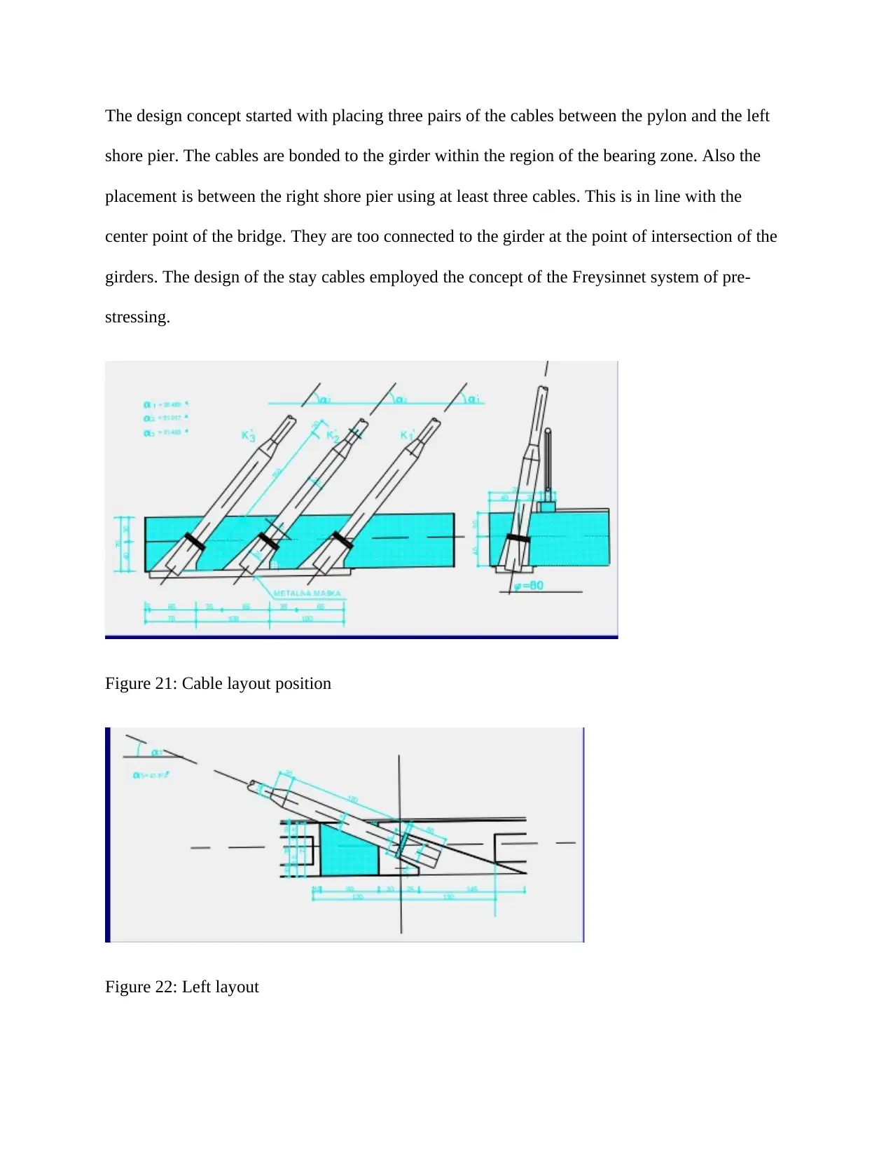
The design concept started with placing three pairs of the cables between the pylon and the left
shore pier. The cables are bonded to the girder within the region of the bearing zone. Also the
placement is between the right shore pier using at least three cables. This is in line with the
center point of the bridge. They are too connected to the girder at the point of intersection of the
girders. The design of the stay cables employed the concept of the Freysinnet system of pre-
stressing.
Figure 21: Cable layout position
Figure 22: Left layout
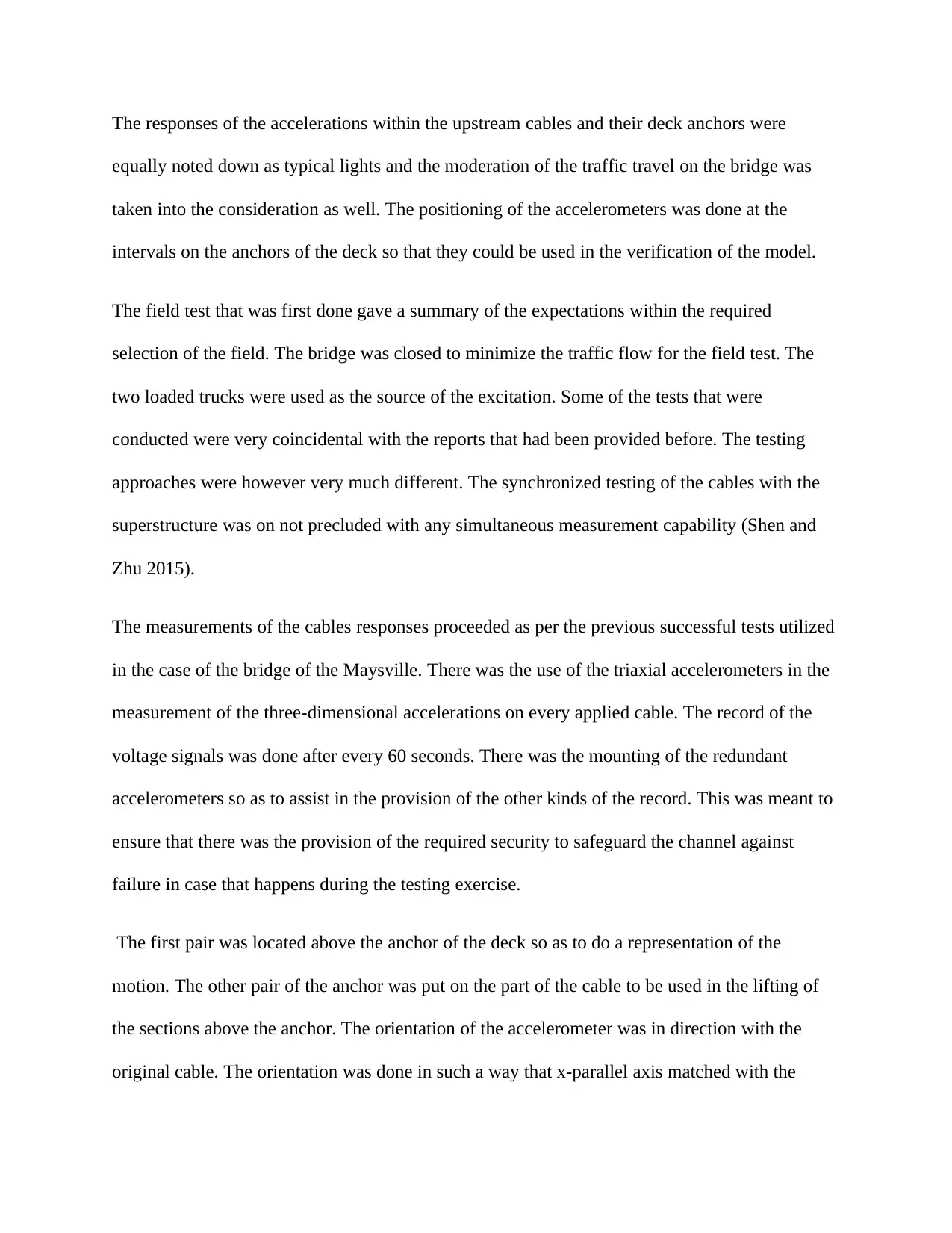
The responses of the accelerations within the upstream cables and their deck anchors were
equally noted down as typical lights and the moderation of the traffic travel on the bridge was
taken into the consideration as well. The positioning of the accelerometers was done at the
intervals on the anchors of the deck so that they could be used in the verification of the model.
The field test that was first done gave a summary of the expectations within the required
selection of the field. The bridge was closed to minimize the traffic flow for the field test. The
two loaded trucks were used as the source of the excitation. Some of the tests that were
conducted were very coincidental with the reports that had been provided before. The testing
approaches were however very much different. The synchronized testing of the cables with the
superstructure was on not precluded with any simultaneous measurement capability (Shen and
Zhu 2015).
The measurements of the cables responses proceeded as per the previous successful tests utilized
in the case of the bridge of the Maysville. There was the use of the triaxial accelerometers in the
measurement of the three-dimensional accelerations on every applied cable. The record of the
voltage signals was done after every 60 seconds. There was the mounting of the redundant
accelerometers so as to assist in the provision of the other kinds of the record. This was meant to
ensure that there was the provision of the required security to safeguard the channel against
failure in case that happens during the testing exercise.
The first pair was located above the anchor of the deck so as to do a representation of the
motion. The other pair of the anchor was put on the part of the cable to be used in the lifting of
the sections above the anchor. The orientation of the accelerometer was in direction with the
original cable. The orientation was done in such a way that x-parallel axis matched with the
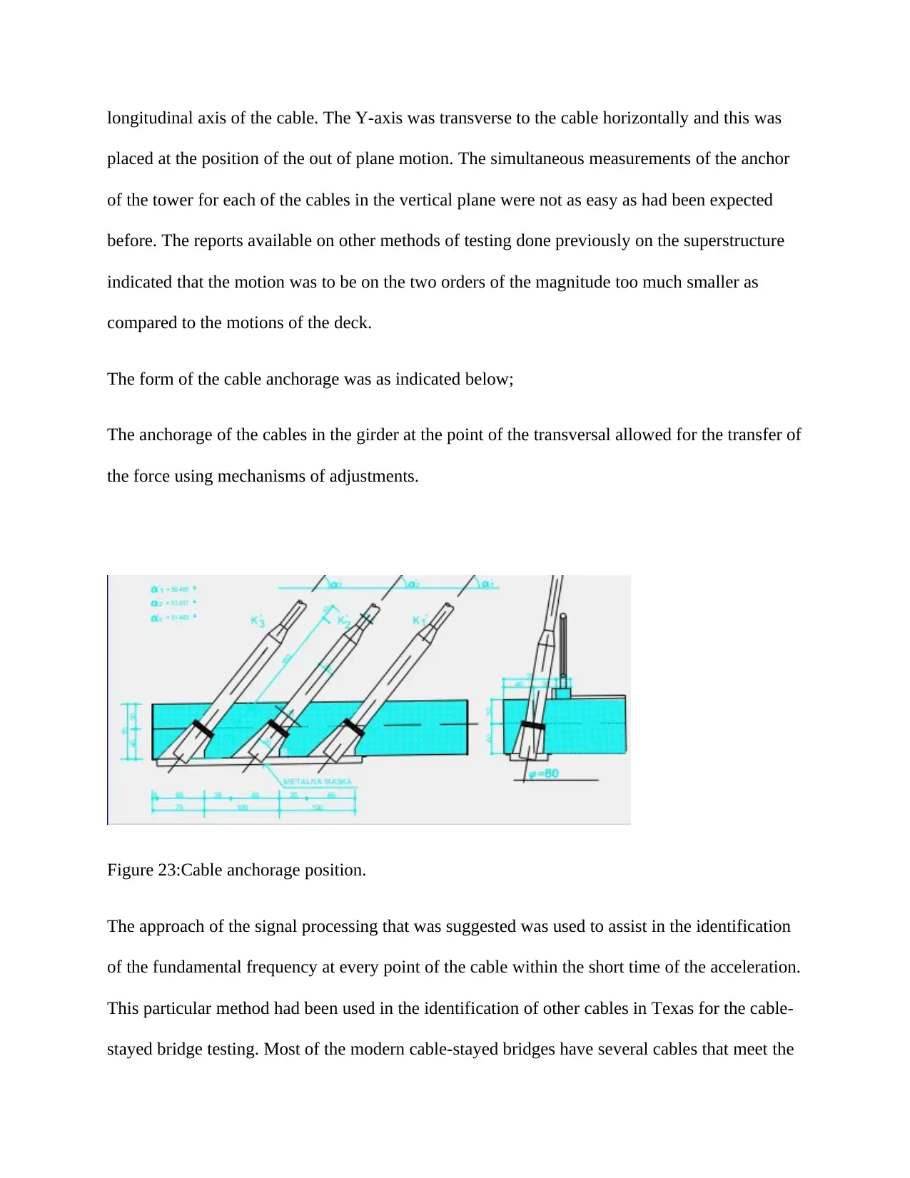
longitudinal axis of the cable. The Y-axis was transverse to the cable horizontally and this was
placed at the position of the out of plane motion. The simultaneous measurements of the anchor
of the tower for each of the cables in the vertical plane were not as easy as had been expected
before. The reports available on other methods of testing done previously on the superstructure
indicated that the motion was to be on the two orders of the magnitude too much smaller as
compared to the motions of the deck.
The form of the cable anchorage was as indicated below;
The anchorage of the cables in the girder at the point of the transversal allowed for the transfer of
the force using mechanisms of adjustments.
Figure 23:Cable anchorage position.
The approach of the signal processing that was suggested was used to assist in the identification
of the fundamental frequency at every point of the cable within the short time of the acceleration.
This particular method had been used in the identification of other cables in Texas for the cable-
stayed bridge testing. Most of the modern cable-stayed bridges have several cables that meet the
Secure Best Marks with AI Grader
Need help grading? Try our AI Grader for instant feedback on your assignments.
engineering requirements of the designs. The most important component that must be determined
is the fundamental frequency of the cable that normally ranges from 0.5 to 3 HZ. In order to
determine the modal frequencies of the deck, low frequencies of the known bandwidth
processing are normally preferred. According to the experience that is obtained from the field,
more than five days will be needed for proper acquisition of the data regarding the bridge of the
Owensboro.
The cables that were used in the cases of the Owensboro Bridge have a very unique response of
the frequency properties and this included the harmonics. This fundamental frequency allowed
for more efficient field testing in the monitoring of the conditions. The techniques of monitoring
the process have been considered crucial in the test. The approach allows for the use of the
records whose life spans are very short ranging from 45 to 60 seconds in the entire length. The
further approach was easily automated in the period of the field testing and this further translates
to the modal evaluation of the cable-stayed bridge. The testing of the field survey on the other 72
cables was done and finally completed within a period of 36 hours (Xu 2013).
Design criteria of the cables
ULS; Maximum tensile force and load bearing capacity
Deformation of the structure of the spanning using SLS
The deformation and stability of the pylon considered both SLS and ULS
Possibility of having one cable replaced
Ability of building and assemblage
The ultimate limit state as defined with the factor of safety of 1.50 for the nominal tensioning of
the stress of the material steel.
The forces of the pre-stressing were inserted into the structure by the use of the stay cable. The
following constraints were considered
The vertical position of the pylon under the influence of the dead load.
The allowable stress and also the range of the strain in the elements of the structure. This was
mainly considered in the case of the structure of the spanning (Yim et al 2013).
In the applications of the components that need rotation or the revolving parts, the analysis will
easily assist in the detection of the families of the uniformly distributed harmonics. This
appeared in the measured signals whenever there is an occurrence of the fault within the system
under the study. The inclined cable-stay response also indicated a family of equally distributed
harmonics. The technique was therefore applied for the cases of the analysis of data
automatically. It was therefore very much easier to determine the fundamental frequencies of the
cable. In order to allow for the understanding of the concept, there has to be a determination of
the frequency using the discrete Fourier transform spectral analysis. The results are returned to
the domain using the second transform. The first and probably the largest peak of the very
frequency are associated with spacing that is adjacent to the expected range of values (Kim,
Jeon, Kim and Park 2013).
In the distinguished information, there was a slight variety of the ordinary cepstrum in the
investigation that was utilized. In alternate applications, there is a limitation in the utilization of
the range on the log scale in order to aid the amplification of the highlights of the inconspicuous
in the whole reaction. The framework was consequently utilized in the straight scale estimations.
There is normally a need of the satisfactory settled individuals from the symphonious family for
the instance of the instance of the pinnacle qualification(Yan and Dai 2012). The encompassing
excitation of the link stayed connect that created from the activity or the breeze itself fulfilled the
requirements of the test in the whole hands on work. The average precedent that had been given
in the above delineation utilized almost 60 seconds for the achievement. There was an
examination that was performed with the end goal to aid the underdoing of the effects of the
chose sizes of the range. The bigger FFT sizes gave figures near close pinnacle of the cepstrum.
The determination of the parameters was done according to the chosen robotized arrangement of
distinguishing proof.
An investigation was directed under this field to aid the comprehension of the impact of utilizing
diverse sizes to ascertain the cepstrum. With the bigger sizes of FFT, the pinnacle shows up on
the zero of the cepstrum. The parameters were decided for the most extreme robotization of the
frequencies of the link. The frequencies might be diverse relying upon the test that had been
directed. The adjustment in the time was given right away. The time space gives the goals of the
change in the distinguished recurrence. This was conceivable considering that the period for
predominance is contrarily corresponding to the major recurrence. The shorter links enrolled
shorter recurrence when contrasted with the more drawn out links.
Substructure
The bridge had a substructure of the two piers whose type is a abutment. This was connected to
the pylon foundation.
Paraphrase This Document
Need a fresh take? Get an instant paraphrase of this document with our AI Paraphraser
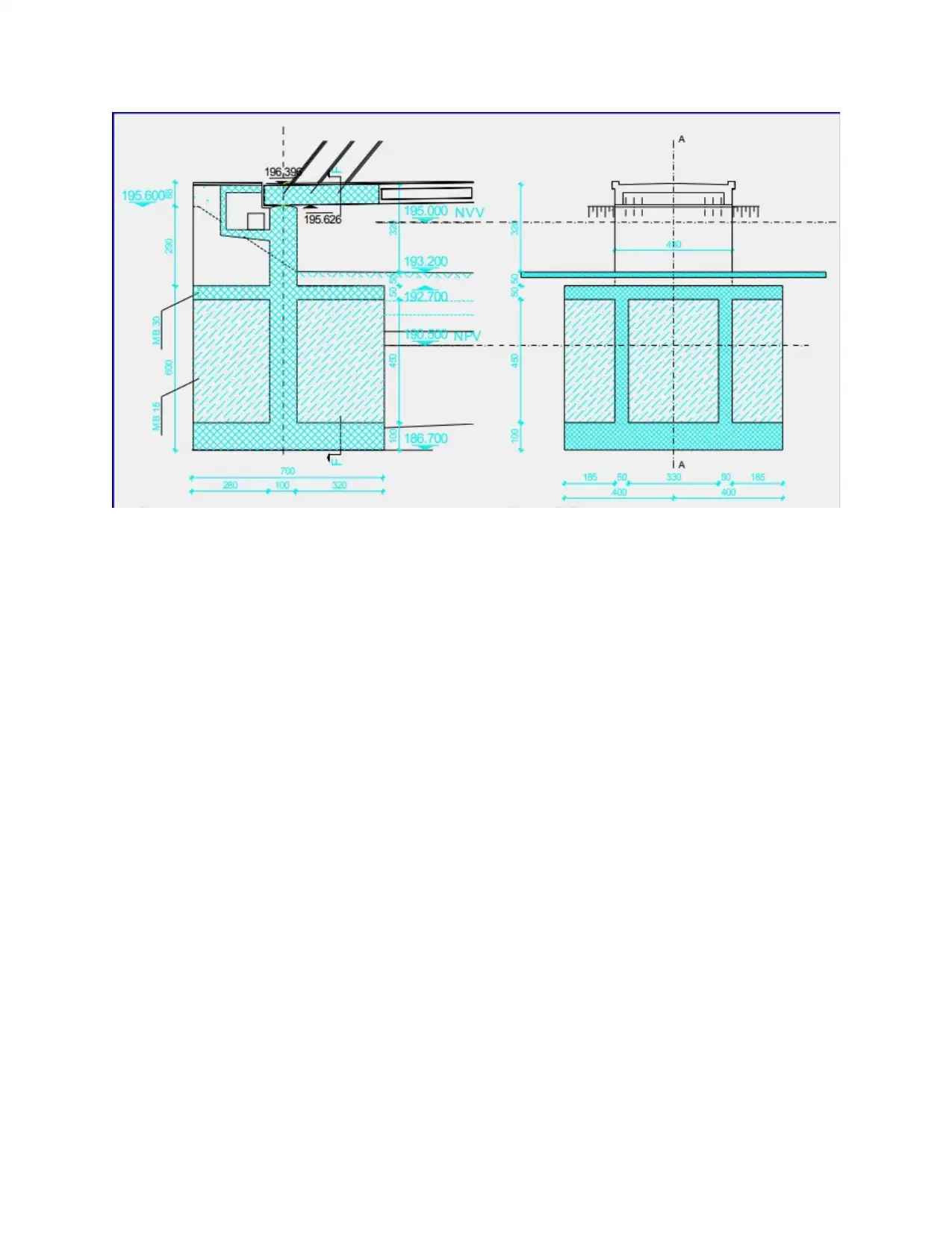
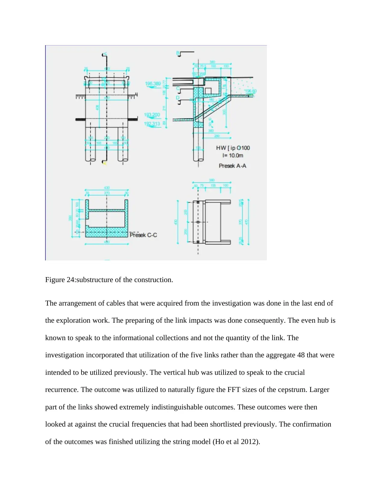
Figure 24:substructure of the construction.
The arrangement of cables that were acquired from the investigation was done in the last end of
the exploration work. The preparing of the link impacts was done consequently. The even hub is
known to speak to the informational collections and not the quantity of the link. The
investigation incorporated that utilization of the five links rather than the aggregate 48 that were
intended to be utilized previously. The vertical hub was utilized to speak to the crucial
recurrence. The outcome was utilized to naturally figure the FFT sizes of the cepstrum. Larger
part of the links showed extremely indistinguishable outcomes. These outcomes were then
looked at against the crucial frequencies that had been shortlisted previously. The confirmation
of the outcomes was finished utilizing the string model (Ho et al 2012).

In the above condition speaks to the essential recurrence that is seen inside the prerequisite every
second. The length of the feet was taken as L. There was the foundation of the relationship
between's the key frequencies and the frequencies that were acquired previously. The gathering
of the distinguished strategy was inside the goals of the standard information. The higher
frequencies were gotten for the instance of the shorter links. As this is run of the mill for the
instances of the flag examination and the field testing that had littler FFT. A portion of the
frequencies that were available couldn't distinguish themselves appropriately with the recurrence
of the rigid string. In the instances of the links that are generally littler, the examination of the
data of the information should be possible utilizing a hand. The determination of the method of
the information preparing gave enhanced outcomes. From the outcomes that were gotten to begin
with, it could be seen that the links of the Owensboro Bridge ought to be adequately energized
by the breeze or by the breeze (Larsen and Larose 2015).
Pylon Design
Reinforcement plan for the pylon
Secure Best Marks with AI Grader
Need help grading? Try our AI Grader for instant feedback on your assignments.
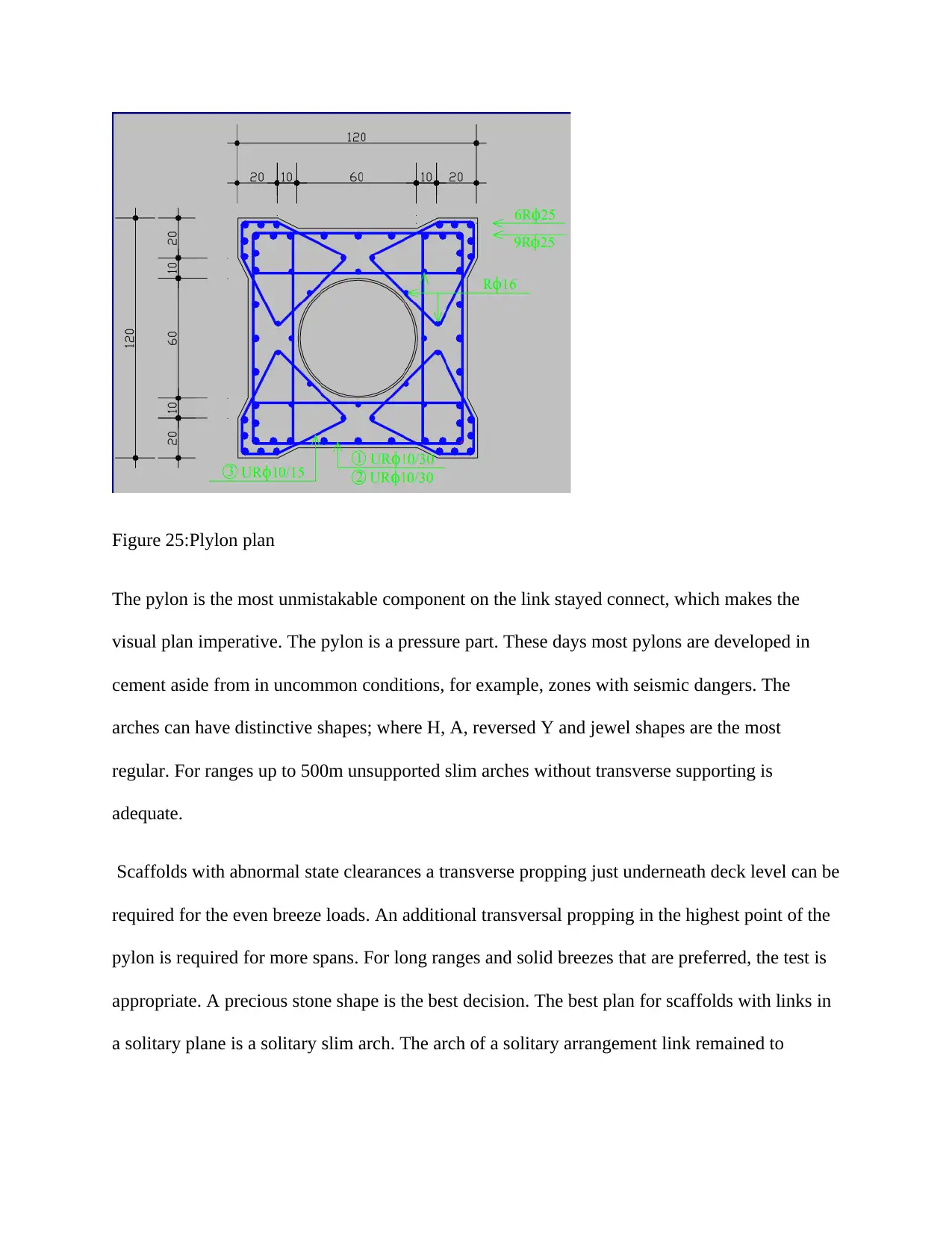
Figure 25:Plylon plan
The pylon is the most unmistakable component on the link stayed connect, which makes the
visual plan imperative. The pylon is a pressure part. These days most pylons are developed in
cement aside from in uncommon conditions, for example, zones with seismic dangers. The
arches can have distinctive shapes; where H, A, reversed Y and jewel shapes are the most
regular. For ranges up to 500m unsupported slim arches without transverse supporting is
adequate.
Scaffolds with abnormal state clearances a transverse propping just underneath deck level can be
required for the even breeze loads. An additional transversal propping in the highest point of the
pylon is required for more spans. For long ranges and solid breezes that are preferred, the test is
appropriate. A precious stone shape is the best decision. The best plan for scaffolds with links in
a solitary plane is a solitary slim arch. The arch of a solitary arrangement link remained to
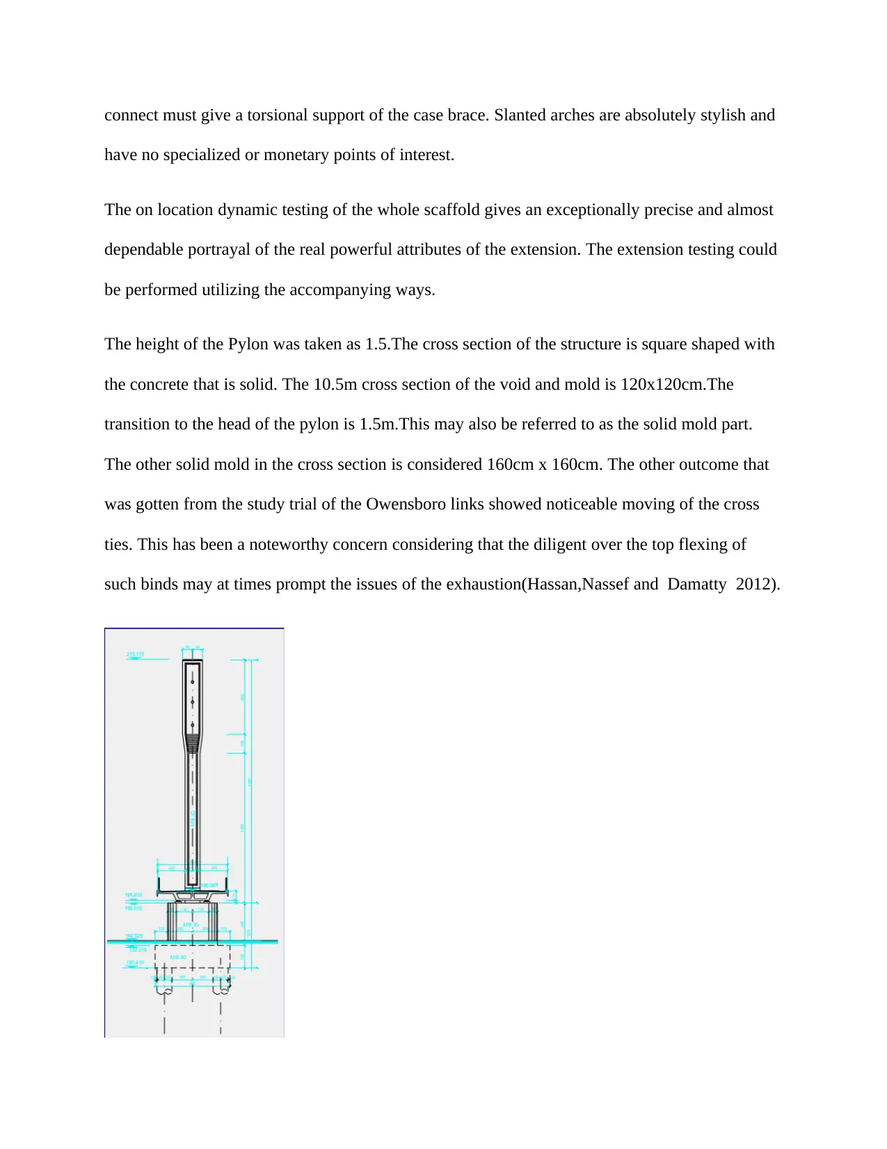
connect must give a torsional support of the case brace. Slanted arches are absolutely stylish and
have no specialized or monetary points of interest.
The on location dynamic testing of the whole scaffold gives an exceptionally precise and almost
dependable portrayal of the real powerful attributes of the extension. The extension testing could
be performed utilizing the accompanying ways.
The height of the Pylon was taken as 1.5.The cross section of the structure is square shaped with
the concrete that is solid. The 10.5m cross section of the void and mold is 120x120cm.The
transition to the head of the pylon is 1.5m.This may also be referred to as the solid mold part.
The other solid mold in the cross section is considered 160cm x 160cm. The other outcome that
was gotten from the study trial of the Owensboro links showed noticeable moving of the cross
ties. This has been a noteworthy concern considering that the diligent over the top flexing of
such binds may at times prompt the issues of the exhaustion(Hassan,Nassef and Damatty 2012).
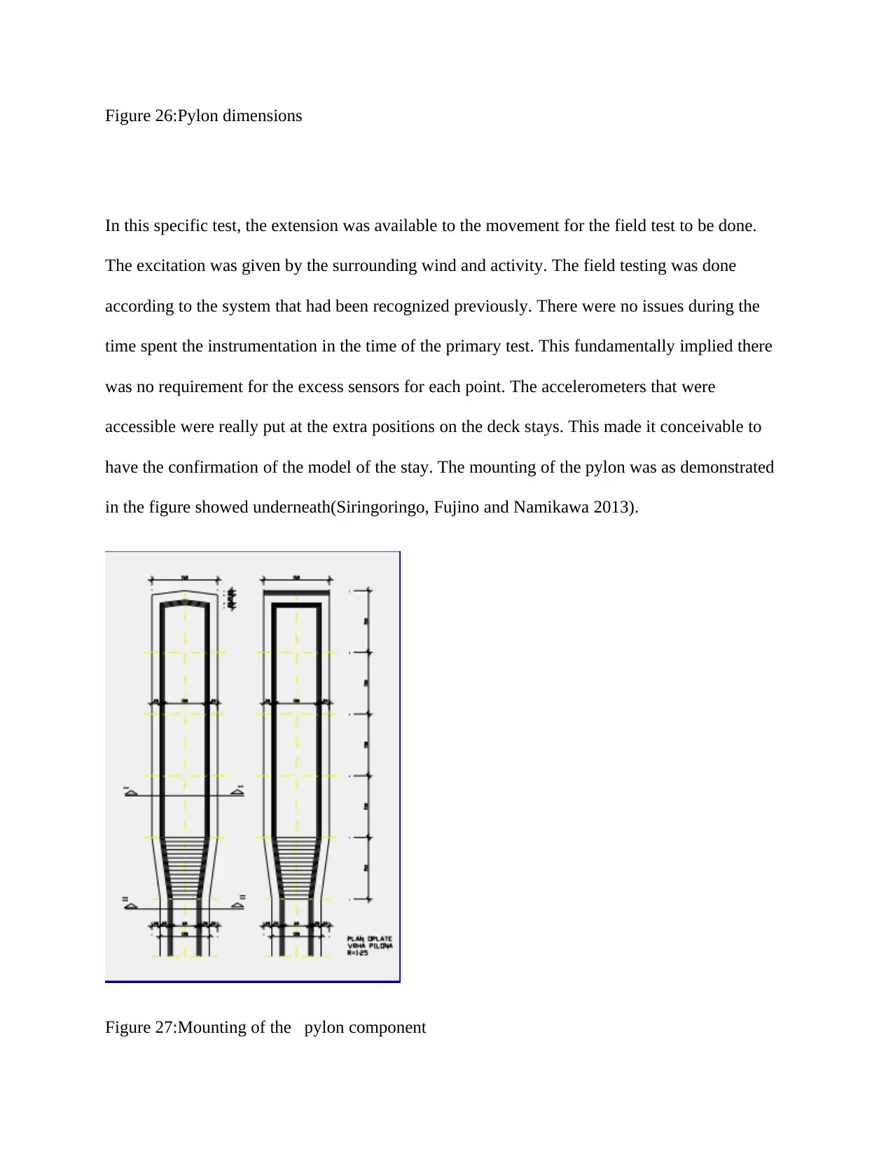
Figure 26:Pylon dimensions
In this specific test, the extension was available to the movement for the field test to be done.
The excitation was given by the surrounding wind and activity. The field testing was done
according to the system that had been recognized previously. There were no issues during the
time spent the instrumentation in the time of the primary test. This fundamentally implied there
was no requirement for the excess sensors for each point. The accelerometers that were
accessible were really put at the extra positions on the deck stays. This made it conceivable to
have the confirmation of the model of the stay. The mounting of the pylon was as demonstrated
in the figure showed underneath(Siringoringo, Fujino and Namikawa 2013).
Figure 27:Mounting of the pylon component
Paraphrase This Document
Need a fresh take? Get an instant paraphrase of this document with our AI Paraphraser
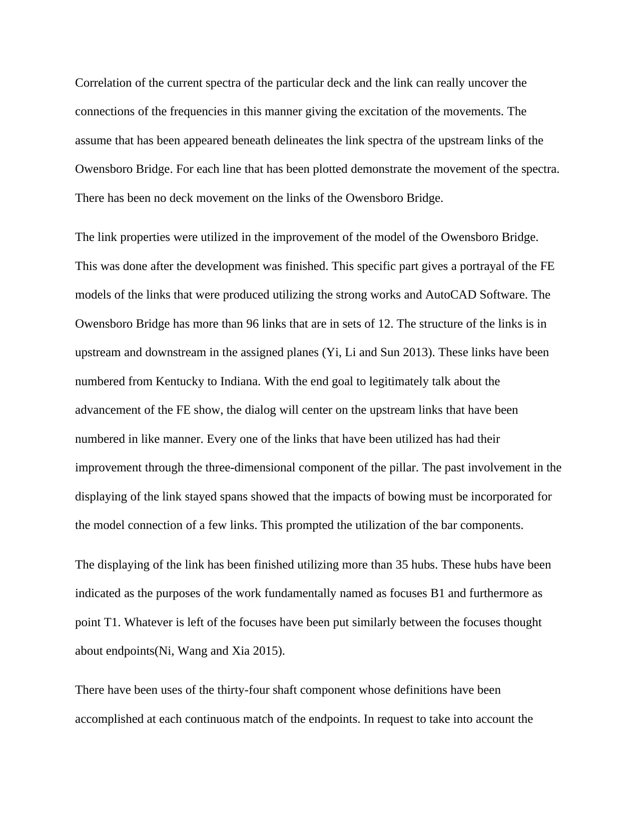
Correlation of the current spectra of the particular deck and the link can really uncover the
connections of the frequencies in this manner giving the excitation of the movements. The
assume that has been appeared beneath delineates the link spectra of the upstream links of the
Owensboro Bridge. For each line that has been plotted demonstrate the movement of the spectra.
There has been no deck movement on the links of the Owensboro Bridge.
The link properties were utilized in the improvement of the model of the Owensboro Bridge.
This was done after the development was finished. This specific part gives a portrayal of the FE
models of the links that were produced utilizing the strong works and AutoCAD Software. The
Owensboro Bridge has more than 96 links that are in sets of 12. The structure of the links is in
upstream and downstream in the assigned planes (Yi, Li and Sun 2013). These links have been
numbered from Kentucky to Indiana. With the end goal to legitimately talk about the
advancement of the FE show, the dialog will center on the upstream links that have been
numbered in like manner. Every one of the links that have been utilized has had their
improvement through the three-dimensional component of the pillar. The past involvement in the
displaying of the link stayed spans showed that the impacts of bowing must be incorporated for
the model connection of a few links. This prompted the utilization of the bar components.
The displaying of the link has been finished utilizing more than 35 hubs. These hubs have been
indicated as the purposes of the work fundamentally named as focuses B1 and furthermore as
point T1. Whatever is left of the focuses have been put similarly between the focuses thought
about endpoints(Ni, Wang and Xia 2015).
There have been uses of the thirty-four shaft component whose definitions have been
accomplished at each continuous match of the endpoints. In request to take into account the
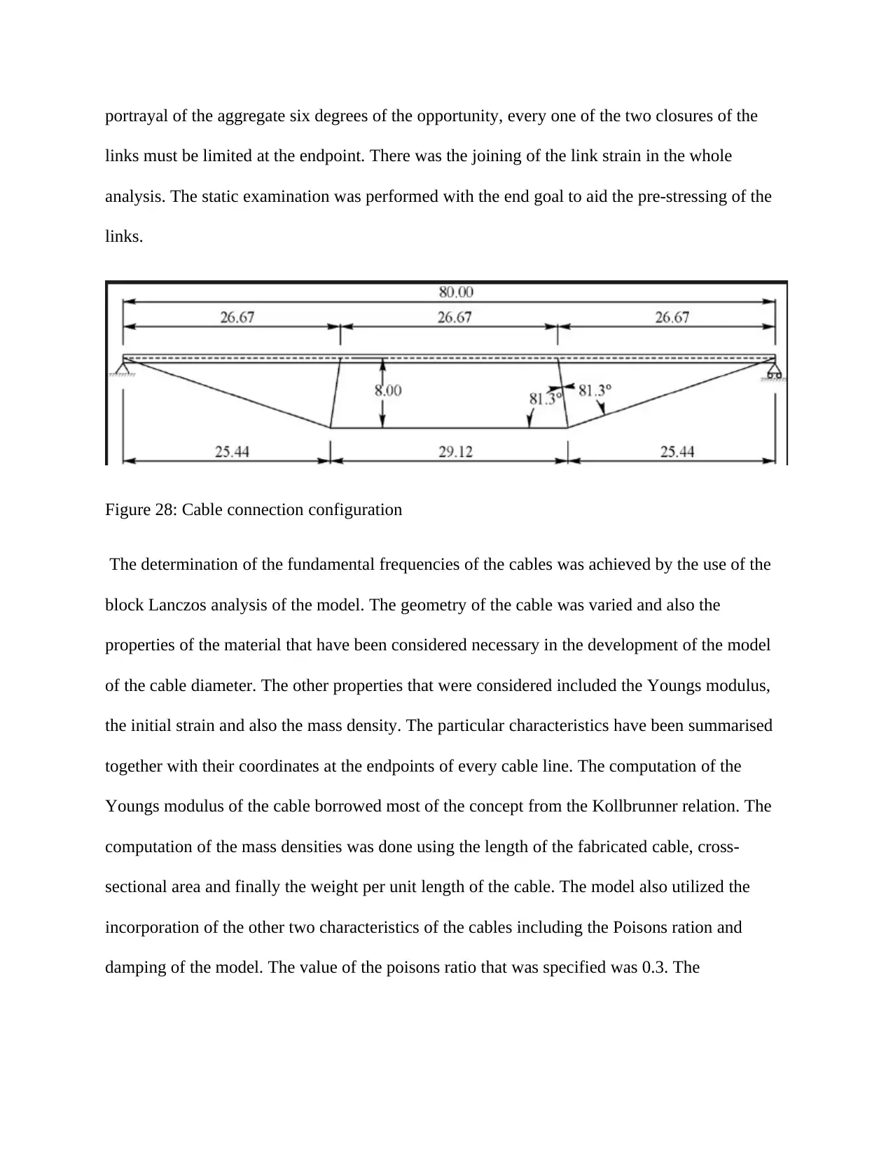
portrayal of the aggregate six degrees of the opportunity, every one of the two closures of the
links must be limited at the endpoint. There was the joining of the link strain in the whole
analysis. The static examination was performed with the end goal to aid the pre-stressing of the
links.
Figure 28: Cable connection configuration
The determination of the fundamental frequencies of the cables was achieved by the use of the
block Lanczos analysis of the model. The geometry of the cable was varied and also the
properties of the material that have been considered necessary in the development of the model
of the cable diameter. The other properties that were considered included the Youngs modulus,
the initial strain and also the mass density. The particular characteristics have been summarised
together with their coordinates at the endpoints of every cable line. The computation of the
Youngs modulus of the cable borrowed most of the concept from the Kollbrunner relation. The
computation of the mass densities was done using the length of the fabricated cable, cross-
sectional area and finally the weight per unit length of the cable. The model also utilized the
incorporation of the other two characteristics of the cables including the Poisons ration and
damping of the model. The value of the poisons ratio that was specified was 0.3. The

specification of the model damping was achieved at 0.0025. It is important to note that the
damping of the modal does not actually enter the commonly known modes
The fundamental results compared with the test frequencies
Upstream cable Field in HZ String in HZ Analysis1(free) Analysis2(restrained)
1 0.5680 0.5560 0.6133 0.6113
2 0.6253 0.5742 0.6152 0.6075
3 0.6945 0.6849 0.7521 0.7372
4 0.6945 0.7354 0.7640 0.7454
5 0.7812 0.8282 0.8457 0.8234
The plotting of the frequencies of the above data against the numbers of t individual cables used
will give results of the graph shown or indicated below (Shen and Zhu 2015).
The addition of the restrainers to the model of the cable sets and additional elements of the beam
will assist in the connection of the cable nodes at the closed locations of the cables. The
installations of the restrainers did not put into the considerations the locations of the specific
drawings in relation to the points of the operations. The establishment of the restrainer location
within the model was achieved by the use of the geometry that had been highlighted in the
drawing. The system of the restrainers included the following sub-components: An elastic
interface that is found between the collar and the cable, the threaded stud that has been properly
welded to the cable itself and have its other end screwed into the collar. The previous studies
have indicated that there is lots of dominance of this component within the system. This property
Secure Best Marks with AI Grader
Need help grading? Try our AI Grader for instant feedback on your assignments.
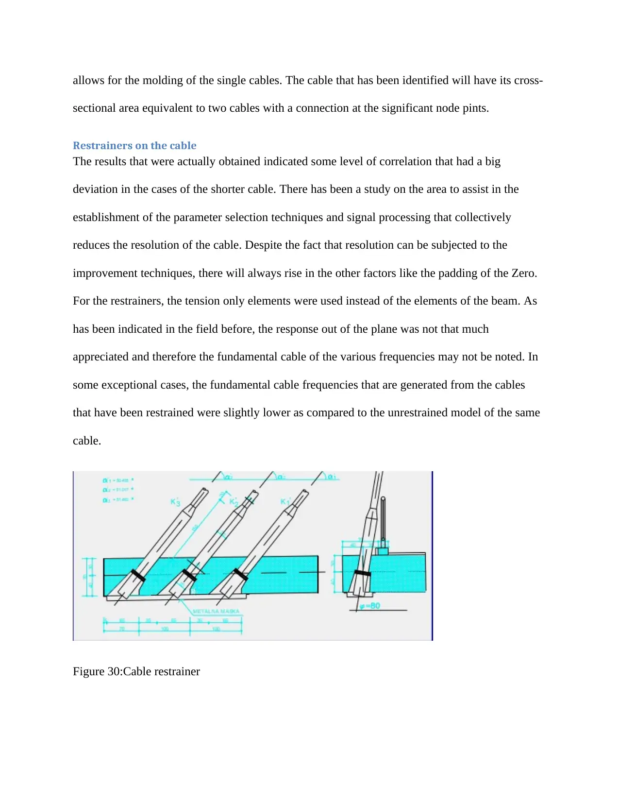
allows for the molding of the single cables. The cable that has been identified will have its cross-
sectional area equivalent to two cables with a connection at the significant node pints.
Restrainers on the cable
The results that were actually obtained indicated some level of correlation that had a big
deviation in the cases of the shorter cable. There has been a study on the area to assist in the
establishment of the parameter selection techniques and signal processing that collectively
reduces the resolution of the cable. Despite the fact that resolution can be subjected to the
improvement techniques, there will always rise in the other factors like the padding of the Zero.
For the restrainers, the tension only elements were used instead of the elements of the beam. As
has been indicated in the field before, the response out of the plane was not that much
appreciated and therefore the fundamental cable of the various frequencies may not be noted. In
some exceptional cases, the fundamental cable frequencies that are generated from the cables
that have been restrained were slightly lower as compared to the unrestrained model of the same
cable.
Figure 30:Cable restrainer
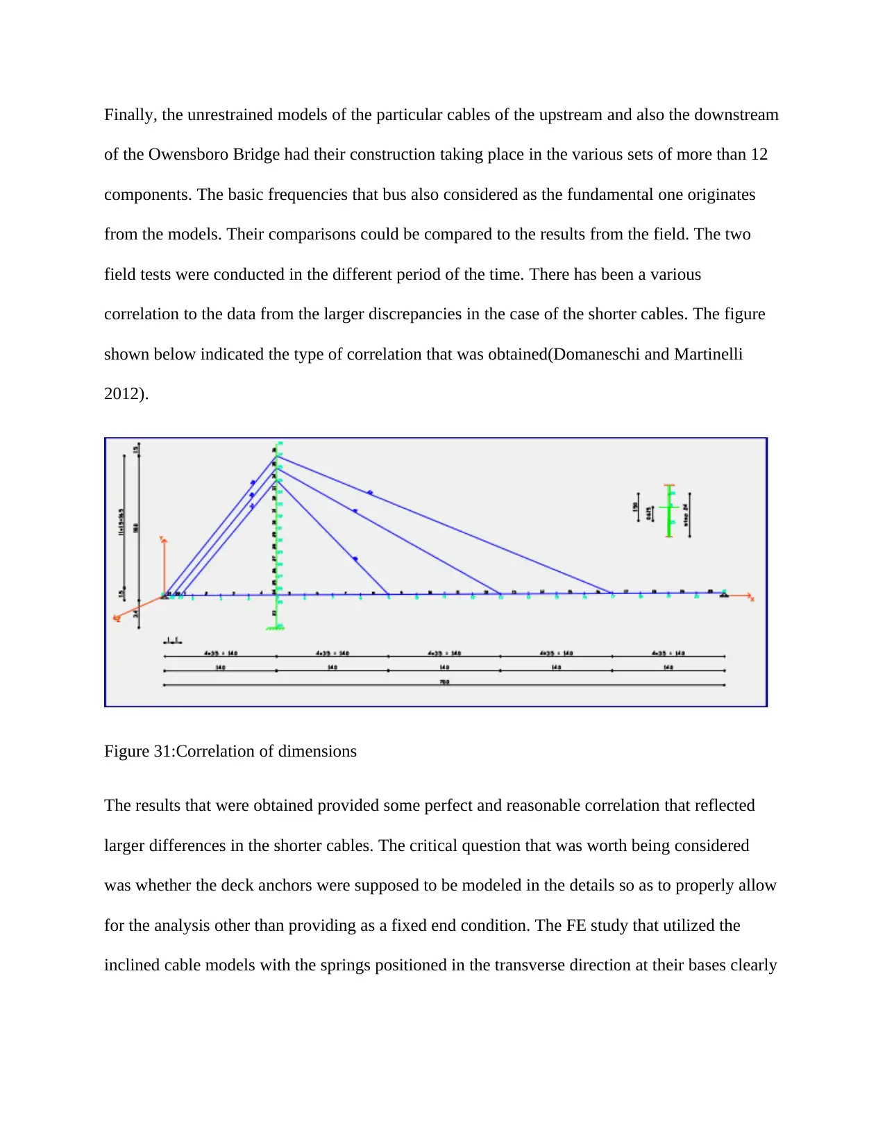
Finally, the unrestrained models of the particular cables of the upstream and also the downstream
of the Owensboro Bridge had their construction taking place in the various sets of more than 12
components. The basic frequencies that bus also considered as the fundamental one originates
from the models. Their comparisons could be compared to the results from the field. The two
field tests were conducted in the different period of the time. There has been a various
correlation to the data from the larger discrepancies in the case of the shorter cables. The figure
shown below indicated the type of correlation that was obtained(Domaneschi and Martinelli
2012).
Figure 31:Correlation of dimensions
The results that were obtained provided some perfect and reasonable correlation that reflected
larger differences in the shorter cables. The critical question that was worth being considered
was whether the deck anchors were supposed to be modeled in the details so as to properly allow
for the analysis other than providing as a fixed end condition. The FE study that utilized the
inclined cable models with the springs positioned in the transverse direction at their bases clearly
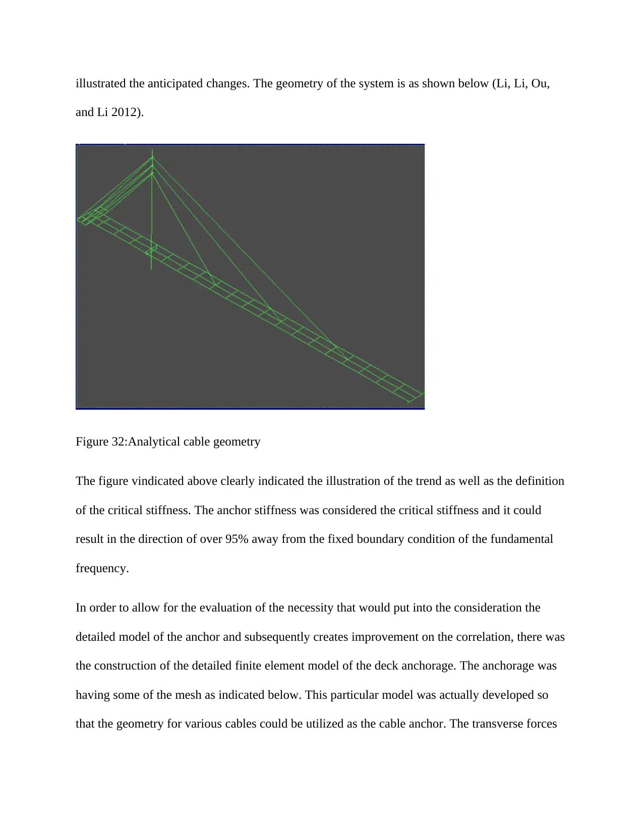
illustrated the anticipated changes. The geometry of the system is as shown below (Li, Li, Ou,
and Li 2012).
Figure 32:Analytical cable geometry
The figure vindicated above clearly indicated the illustration of the trend as well as the definition
of the critical stiffness. The anchor stiffness was considered the critical stiffness and it could
result in the direction of over 95% away from the fixed boundary condition of the fundamental
frequency.
In order to allow for the evaluation of the necessity that would put into the consideration the
detailed model of the anchor and subsequently creates improvement on the correlation, there was
the construction of the detailed finite element model of the deck anchorage. The anchorage was
having some of the mesh as indicated below. This particular model was actually developed so
that the geometry for various cables could be utilized as the cable anchor. The transverse forces
Paraphrase This Document
Need a fresh take? Get an instant paraphrase of this document with our AI Paraphraser
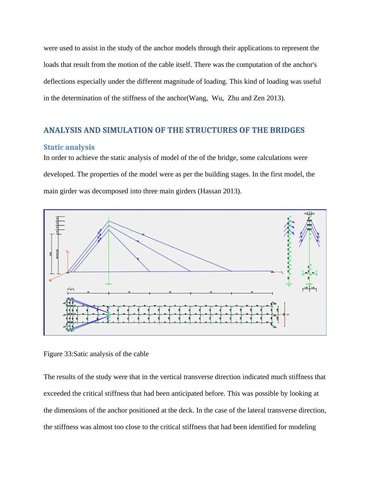
were used to assist in the study of the anchor models through their applications to represent the
loads that result from the motion of the cable itself. There was the computation of the anchor's
deflections especially under the different magnitude of loading. This kind of loading was useful
in the determination of the stiffness of the anchor(Wang, Wu, Zhu and Zen 2013).
ANALYSIS AND SIMULATION OF THE STRUCTURES OF THE BRIDGES
Static analysis
In order to achieve the static analysis of model of the of the bridge, some calculations were
developed. The properties of the model were as per the building stages. In the first model, the
main girder was decomposed into three main girders (Hassan 2013).
Figure 33:Satic analysis of the cable
The results of the study were that in the vertical transverse direction indicated much stiffness that
exceeded the critical stiffness that had been anticipated before. This was possible by looking at
the dimensions of the anchor positioned at the deck. In the case of the lateral transverse direction,
the stiffness was almost too close to the critical stiffness that had been identified for modeling
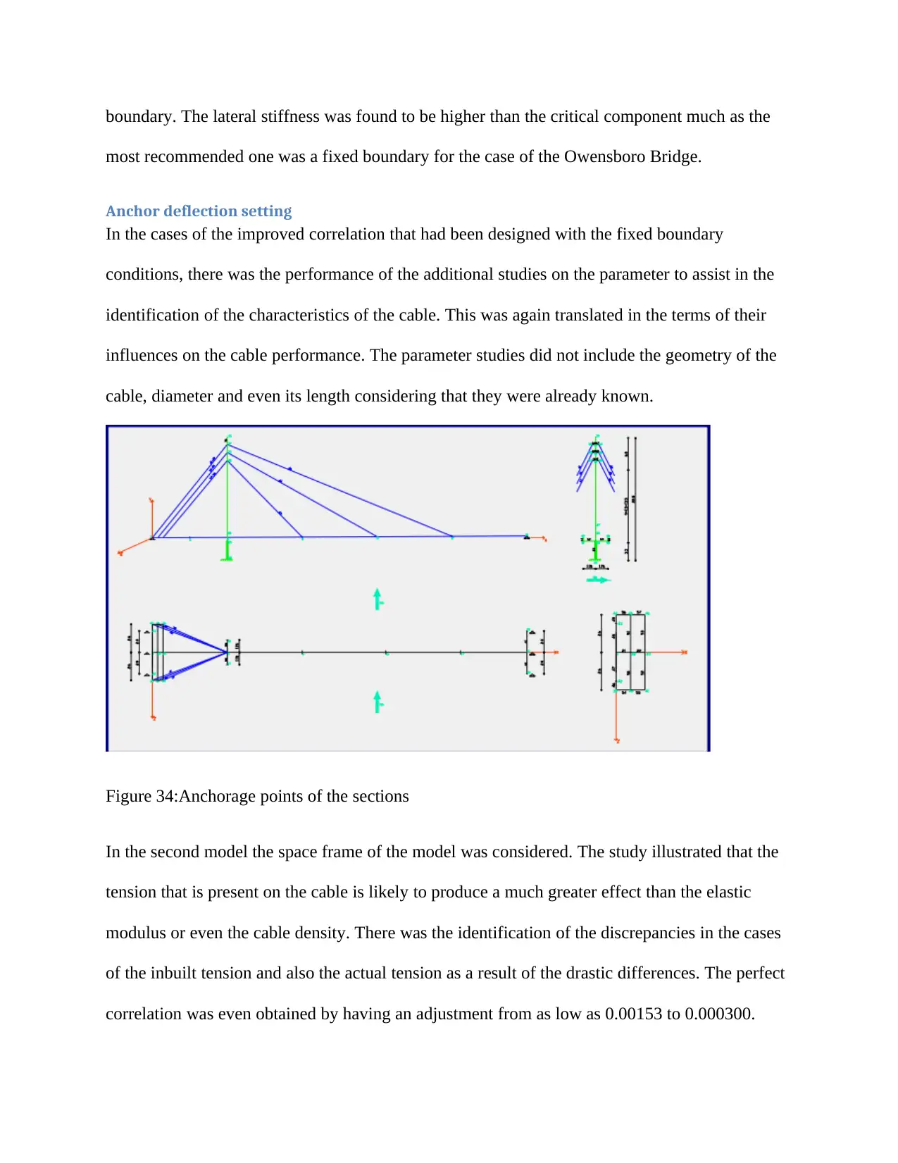
boundary. The lateral stiffness was found to be higher than the critical component much as the
most recommended one was a fixed boundary for the case of the Owensboro Bridge.
Anchor deflection setting
In the cases of the improved correlation that had been designed with the fixed boundary
conditions, there was the performance of the additional studies on the parameter to assist in the
identification of the characteristics of the cable. This was again translated in the terms of their
influences on the cable performance. The parameter studies did not include the geometry of the
cable, diameter and even its length considering that they were already known.
Figure 34:Anchorage points of the sections
In the second model the space frame of the model was considered. The study illustrated that the
tension that is present on the cable is likely to produce a much greater effect than the elastic
modulus or even the cable density. There was the identification of the discrepancies in the cases
of the inbuilt tension and also the actual tension as a result of the drastic differences. The perfect
correlation was even obtained by having an adjustment from as low as 0.00153 to 0.000300.
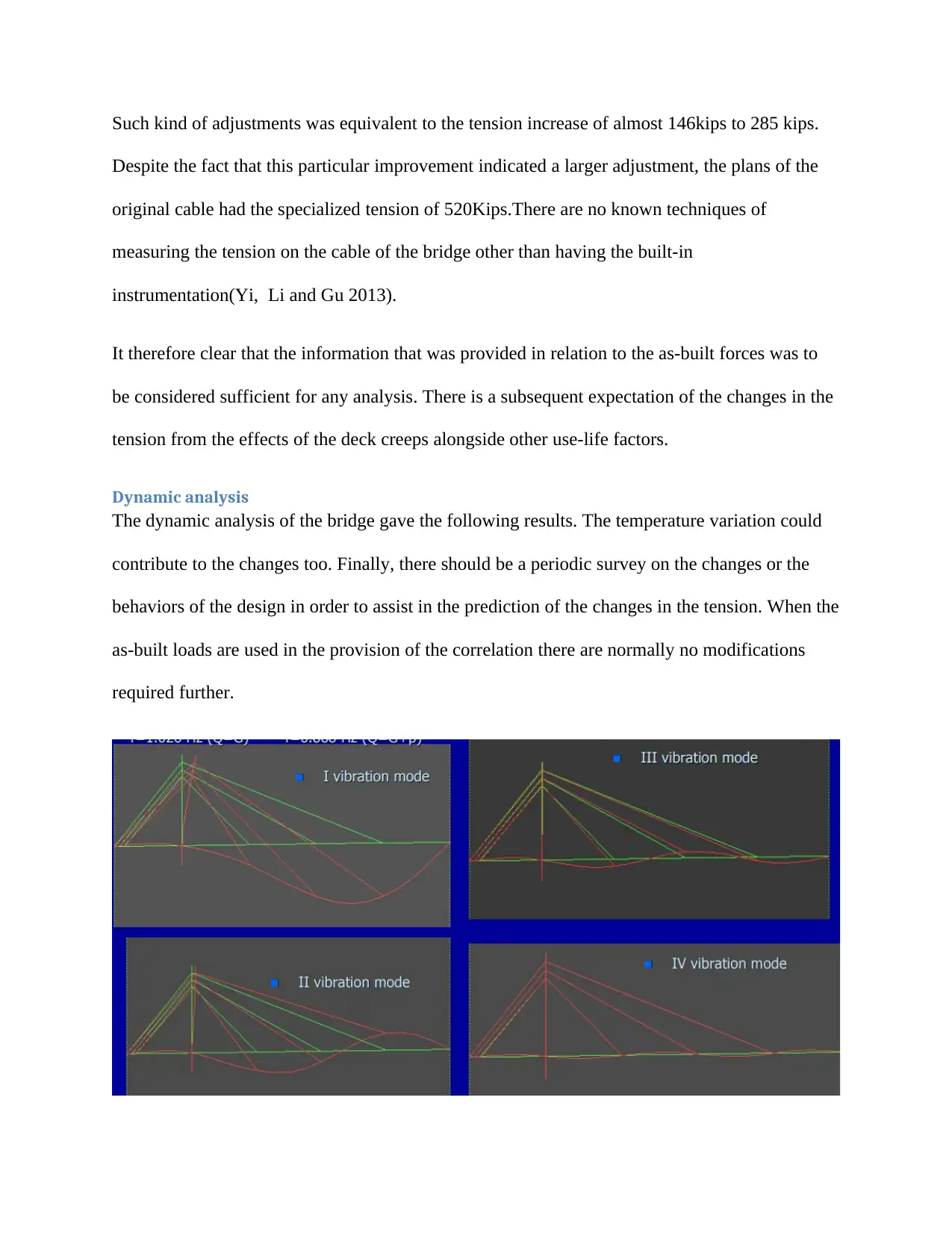
Such kind of adjustments was equivalent to the tension increase of almost 146kips to 285 kips.
Despite the fact that this particular improvement indicated a larger adjustment, the plans of the
original cable had the specialized tension of 520Kips.There are no known techniques of
measuring the tension on the cable of the bridge other than having the built-in
instrumentation(Yi, Li and Gu 2013).
It therefore clear that the information that was provided in relation to the as-built forces was to
be considered sufficient for any analysis. There is a subsequent expectation of the changes in the
tension from the effects of the deck creeps alongside other use-life factors.
Dynamic analysis
The dynamic analysis of the bridge gave the following results. The temperature variation could
contribute to the changes too. Finally, there should be a periodic survey on the changes or the
behaviors of the design in order to assist in the prediction of the changes in the tension. When the
as-built loads are used in the provision of the correlation there are normally no modifications
required further.
Secure Best Marks with AI Grader
Need help grading? Try our AI Grader for instant feedback on your assignments.
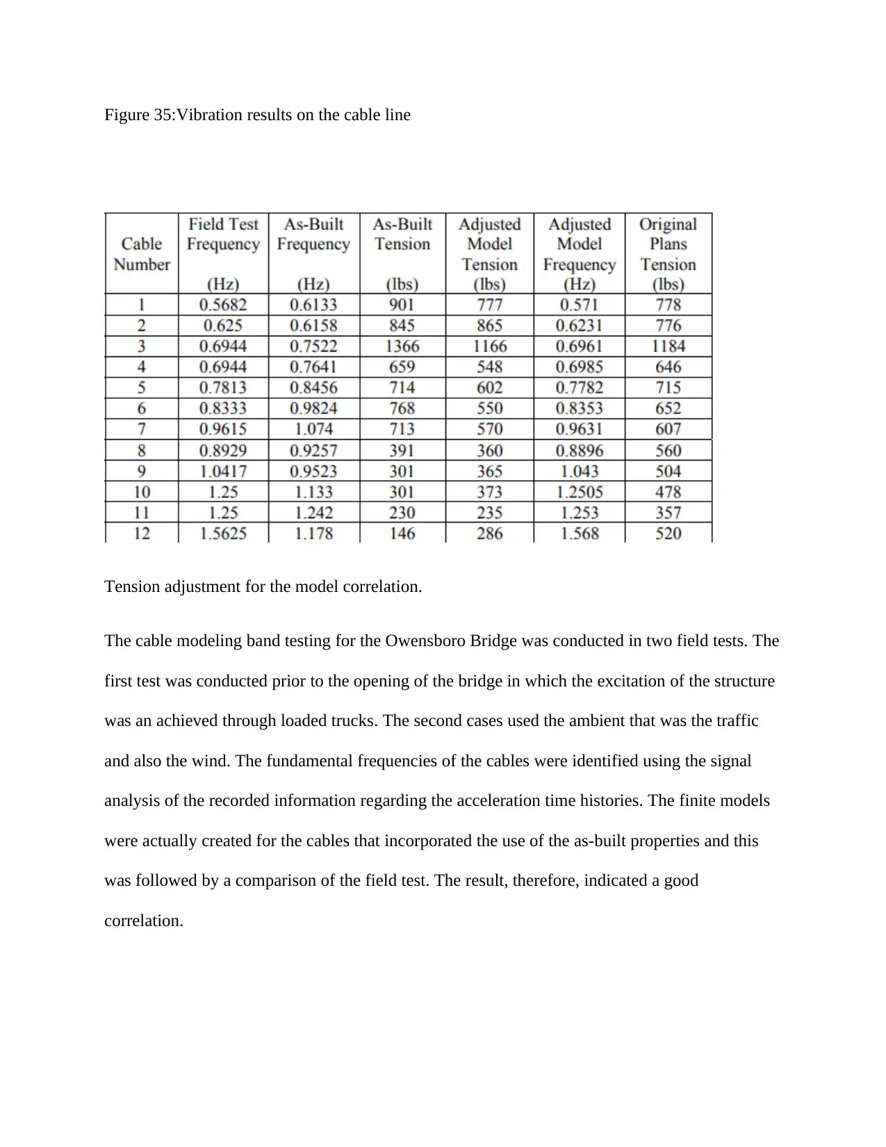
Figure 35:Vibration results on the cable line
Tension adjustment for the model correlation.
The cable modeling band testing for the Owensboro Bridge was conducted in two field tests. The
first test was conducted prior to the opening of the bridge in which the excitation of the structure
was an achieved through loaded trucks. The second cases used the ambient that was the traffic
and also the wind. The fundamental frequencies of the cables were identified using the signal
analysis of the recorded information regarding the acceleration time histories. The finite models
were actually created for the cables that incorporated the use of the as-built properties and this
was followed by a comparison of the field test. The result, therefore, indicated a good
correlation.
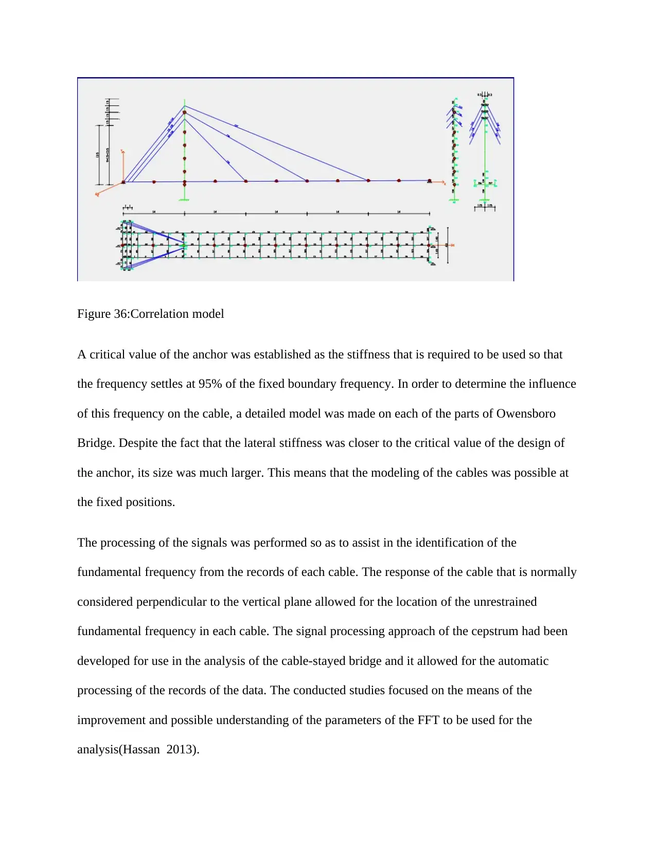
Figure 36:Correlation model
A critical value of the anchor was established as the stiffness that is required to be used so that
the frequency settles at 95% of the fixed boundary frequency. In order to determine the influence
of this frequency on the cable, a detailed model was made on each of the parts of Owensboro
Bridge. Despite the fact that the lateral stiffness was closer to the critical value of the design of
the anchor, its size was much larger. This means that the modeling of the cables was possible at
the fixed positions.
The processing of the signals was performed so as to assist in the identification of the
fundamental frequency from the records of each cable. The response of the cable that is normally
considered perpendicular to the vertical plane allowed for the location of the unrestrained
fundamental frequency in each cable. The signal processing approach of the cepstrum had been
developed for use in the analysis of the cable-stayed bridge and it allowed for the automatic
processing of the records of the data. The conducted studies focused on the means of the
improvement and possible understanding of the parameters of the FFT to be used for the
analysis(Hassan 2013).
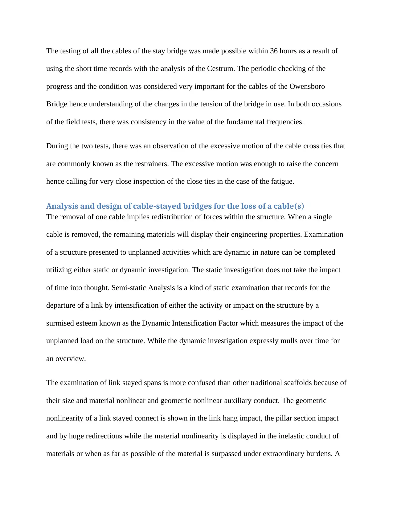
The testing of all the cables of the stay bridge was made possible within 36 hours as a result of
using the short time records with the analysis of the Cestrum. The periodic checking of the
progress and the condition was considered very important for the cables of the Owensboro
Bridge hence understanding of the changes in the tension of the bridge in use. In both occasions
of the field tests, there was consistency in the value of the fundamental frequencies.
During the two tests, there was an observation of the excessive motion of the cable cross ties that
are commonly known as the restrainers. The excessive motion was enough to raise the concern
hence calling for very close inspection of the close ties in the case of the fatigue.
Analysis and design of cable-stayed bridges for the loss of a cable(s)
The removal of one cable implies redistribution of forces within the structure. When a single
cable is removed, the remaining materials will display their engineering properties. Examination
of a structure presented to unplanned activities which are dynamic in nature can be completed
utilizing either static or dynamic investigation. The static investigation does not take the impact
of time into thought. Semi-static Analysis is a kind of static examination that records for the
departure of a link by intensification of either the activity or impact on the structure by a
surmised esteem known as the Dynamic Intensification Factor which measures the impact of the
unplanned load on the structure. While the dynamic investigation expressly mulls over time for
an overview.
The examination of link stayed spans is more confused than other traditional scaffolds because of
their size and material nonlinear and geometric nonlinear auxiliary conduct. The geometric
nonlinearity of a link stayed connect is shown in the link hang impact, the pillar section impact
and by huge redirections while the material nonlinearity is displayed in the inelastic conduct of
materials or when as far as possible of the material is surpassed under extraordinary burdens. A
Paraphrase This Document
Need a fresh take? Get an instant paraphrase of this document with our AI Paraphraser
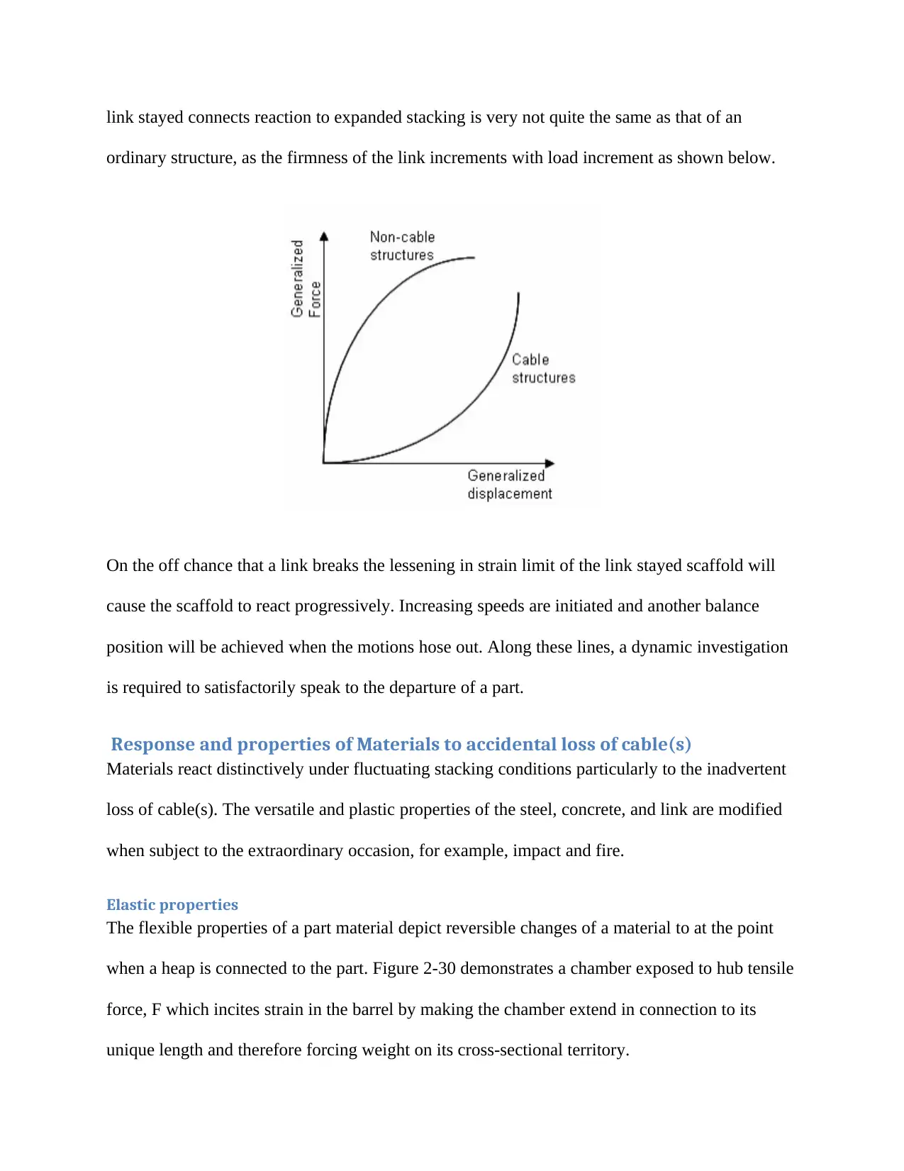
link stayed connects reaction to expanded stacking is very not quite the same as that of an
ordinary structure, as the firmness of the link increments with load increment as shown below.
On the off chance that a link breaks the lessening in strain limit of the link stayed scaffold will
cause the scaffold to react progressively. Increasing speeds are initiated and another balance
position will be achieved when the motions hose out. Along these lines, a dynamic investigation
is required to satisfactorily speak to the departure of a part.
Response and properties of Materials to accidental loss of cable(s)
Materials react distinctively under fluctuating stacking conditions particularly to the inadvertent
loss of cable(s). The versatile and plastic properties of the steel, concrete, and link are modified
when subject to the extraordinary occasion, for example, impact and fire.
Elastic properties
The flexible properties of a part material depict reversible changes of a material to at the point
when a heap is connected to the part. Figure 2-30 demonstrates a chamber exposed to hub tensile
force, F which incites strain in the barrel by making the chamber extend in connection to its
unique length and therefore forcing weight on its cross-sectional territory.
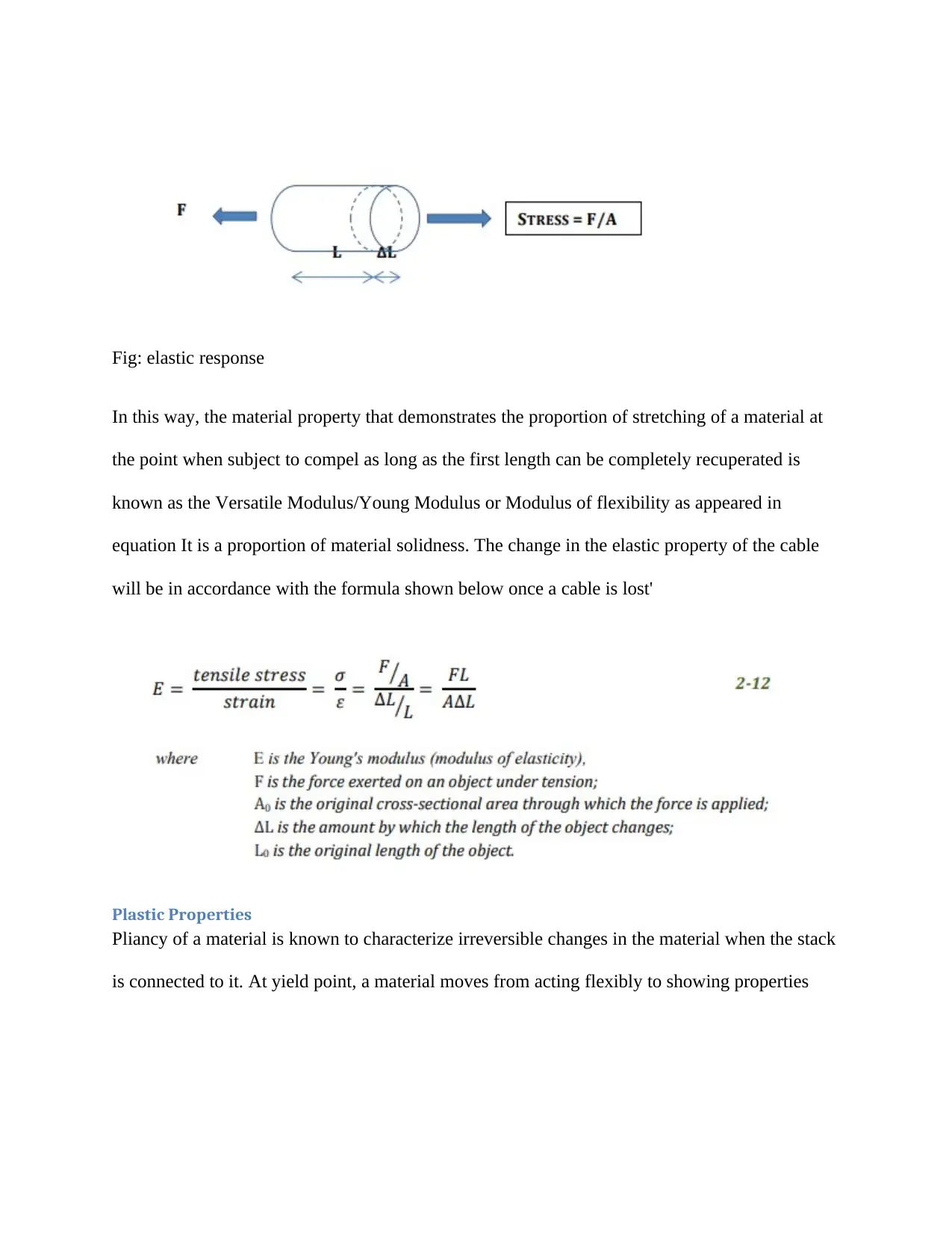
Fig: elastic response
In this way, the material property that demonstrates the proportion of stretching of a material at
the point when subject to compel as long as the first length can be completely recuperated is
known as the Versatile Modulus/Young Modulus or Modulus of flexibility as appeared in
equation It is a proportion of material solidness. The change in the elastic property of the cable
will be in accordance with the formula shown below once a cable is lost'
Plastic Properties
Pliancy of a material is known to characterize irreversible changes in the material when the stack
is connected to it. At yield point, a material moves from acting flexibly to showing properties
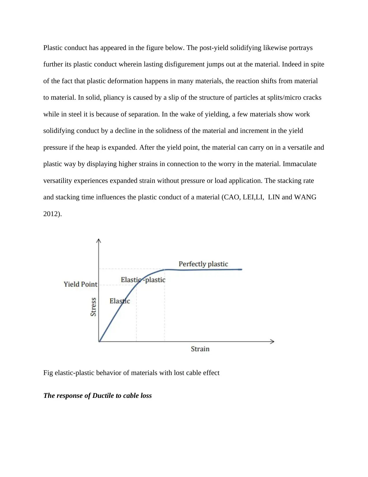
Plastic conduct has appeared in the figure below. The post-yield solidifying likewise portrays
further its plastic conduct wherein lasting disfigurement jumps out at the material. Indeed in spite
of the fact that plastic deformation happens in many materials, the reaction shifts from material
to material. In solid, pliancy is caused by a slip of the structure of particles at splits/micro cracks
while in steel it is because of separation. In the wake of yielding, a few materials show work
solidifying conduct by a decline in the solidness of the material and increment in the yield
pressure if the heap is expanded. After the yield point, the material can carry on in a versatile and
plastic way by displaying higher strains in connection to the worry in the material. Immaculate
versatility experiences expanded strain without pressure or load application. The stacking rate
and stacking time influences the plastic conduct of a material (CAO, LEI,LI, LIN and WANG
2012).
Fig elastic-plastic behavior of materials with lost cable effect
The response of Ductile to cable loss
Secure Best Marks with AI Grader
Need help grading? Try our AI Grader for instant feedback on your assignments.
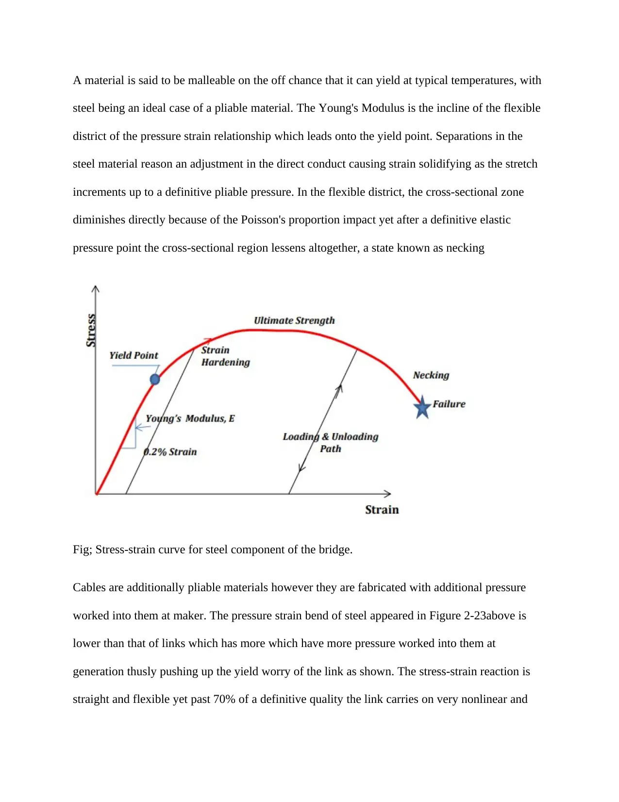
A material is said to be malleable on the off chance that it can yield at typical temperatures, with
steel being an ideal case of a pliable material. The Young's Modulus is the incline of the flexible
district of the pressure strain relationship which leads onto the yield point. Separations in the
steel material reason an adjustment in the direct conduct causing strain solidifying as the stretch
increments up to a definitive pliable pressure. In the flexible district, the cross-sectional zone
diminishes directly because of the Poisson's proportion impact yet after a definitive elastic
pressure point the cross-sectional region lessens altogether, a state known as necking
Fig; Stress-strain curve for steel component of the bridge.
Cables are additionally pliable materials however they are fabricated with additional pressure
worked into them at maker. The pressure strain bend of steel appeared in Figure 2-23above is
lower than that of links which has more which have more pressure worked into them at
generation thusly pushing up the yield worry of the link as shown. The stress-strain reaction is
straight and flexible yet past 70% of a definitive quality the link carries on very nonlinear and
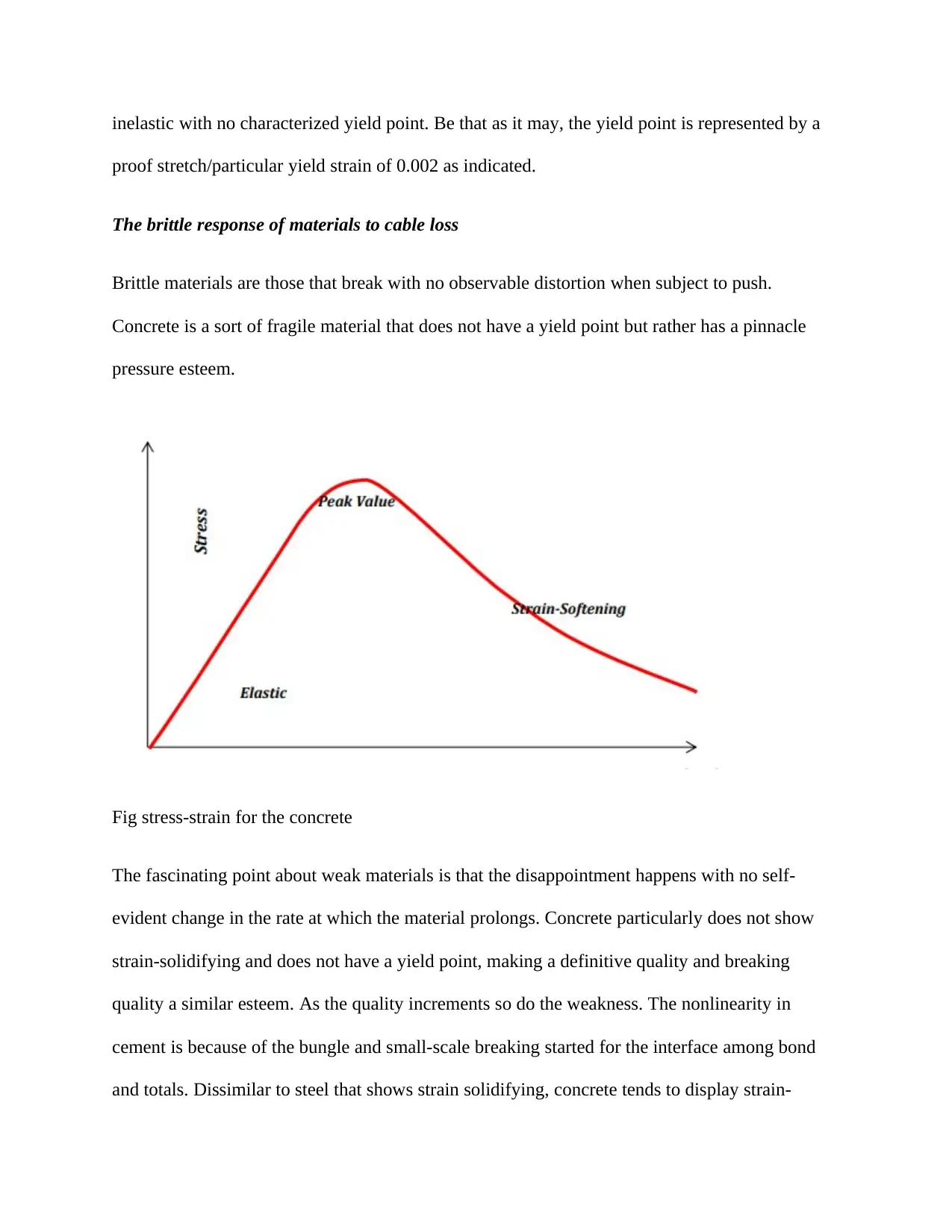
inelastic with no characterized yield point. Be that as it may, the yield point is represented by a
proof stretch/particular yield strain of 0.002 as indicated.
The brittle response of materials to cable loss
Brittle materials are those that break with no observable distortion when subject to push.
Concrete is a sort of fragile material that does not have a yield point but rather has a pinnacle
pressure esteem.
Fig stress-strain for the concrete
The fascinating point about weak materials is that the disappointment happens with no self-
evident change in the rate at which the material prolongs. Concrete particularly does not show
strain-solidifying and does not have a yield point, making a definitive quality and breaking
quality a similar esteem. As the quality increments so do the weakness. The nonlinearity in
cement is because of the bungle and small-scale breaking started for the interface among bond
and totals. Dissimilar to steel that shows strain solidifying, concrete tends to display strain-
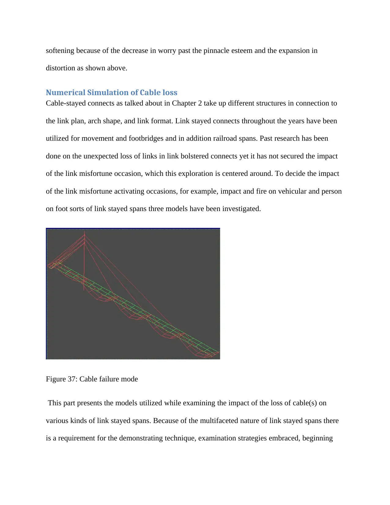
softening because of the decrease in worry past the pinnacle esteem and the expansion in
distortion as shown above.
Numerical Simulation of Cable loss
Cable-stayed connects as talked about in Chapter 2 take up different structures in connection to
the link plan, arch shape, and link format. Link stayed connects throughout the years have been
utilized for movement and footbridges and in addition railroad spans. Past research has been
done on the unexpected loss of links in link bolstered connects yet it has not secured the impact
of the link misfortune occasion, which this exploration is centered around. To decide the impact
of the link misfortune activating occasions, for example, impact and fire on vehicular and person
on foot sorts of link stayed spans three models have been investigated.
Figure 37: Cable failure mode
This part presents the models utilized while examining the impact of the loss of cable(s) on
various kinds of link stayed spans. Because of the multifaceted nature of link stayed spans there
is a requirement for the demonstrating technique, examination strategies embraced, beginning
Paraphrase This Document
Need a fresh take? Get an instant paraphrase of this document with our AI Paraphraser
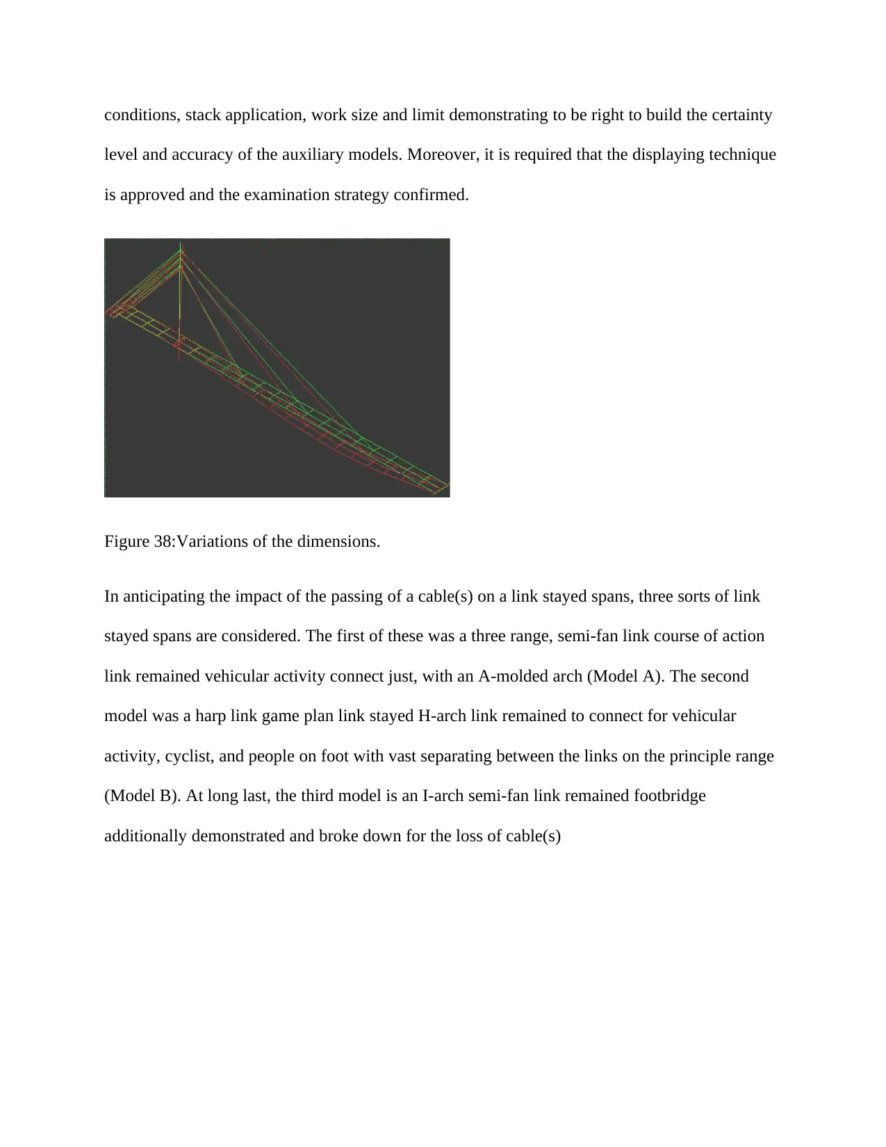
conditions, stack application, work size and limit demonstrating to be right to build the certainty
level and accuracy of the auxiliary models. Moreover, it is required that the displaying technique
is approved and the examination strategy confirmed.
Figure 38:Variations of the dimensions.
In anticipating the impact of the passing of a cable(s) on a link stayed spans, three sorts of link
stayed spans are considered. The first of these was a three range, semi-fan link course of action
link remained vehicular activity connect just, with an A-molded arch (Model A). The second
model was a harp link game plan link stayed H-arch link remained to connect for vehicular
activity, cyclist, and people on foot with vast separating between the links on the principle range
(Model B). At long last, the third model is an I-arch semi-fan link remained footbridge
additionally demonstrated and broke down for the loss of cable(s)
Simulation of platform
Date: Wednesday, October 31, 2018
Designer: Madhav Gami
Study name: SimulationXpress Study
Analysis type: Static
Table of Contents
Assumptions...............................................................2
Model Information.....................................................2
Material Properties....................................................3
Loads and Fixtures......................................................4
Mesh Information.......................................................6
Study Results..............................................................8

Assumptions
Secure Best Marks with AI Grader
Need help grading? Try our AI Grader for instant feedback on your assignments.
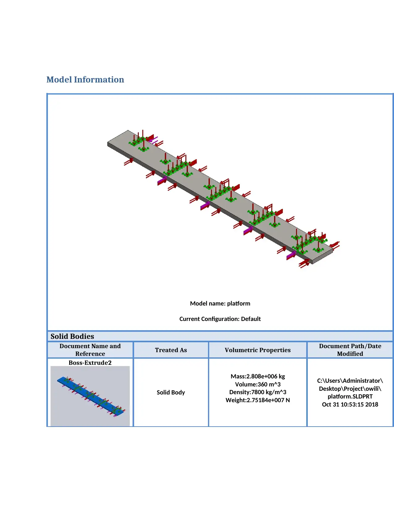
Model Information
Model name: platform
Current Configuration: Default
Solid Bodies
Document Name and
Reference Treated As Volumetric Properties Document Path/Date
Modified
Boss-Extrude2
Solid Body
Mass:2.808e+006 kg
Volume:360 m^3
Density:7800 kg/m^3
Weight:2.75184e+007 N
C:\Users\Administrator\
Desktop\Project\owili\
platform.SLDPRT
Oct 31 10:53:15 2018
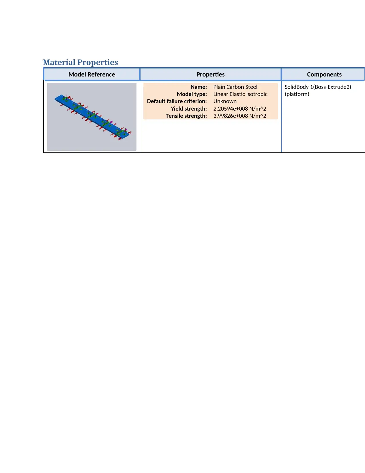
Material Properties
Model Reference Properties Components
Name: Plain Carbon Steel
Model type: Linear Elastic Isotropic
Default failure criterion: Unknown
Yield strength: 2.20594e+008 N/m^2
Tensile strength: 3.99826e+008 N/m^2
SolidBody 1(Boss-Extrude2)
(platform)
Model Reference Properties Components
Name: Plain Carbon Steel
Model type: Linear Elastic Isotropic
Default failure criterion: Unknown
Yield strength: 2.20594e+008 N/m^2
Tensile strength: 3.99826e+008 N/m^2
SolidBody 1(Boss-Extrude2)
(platform)
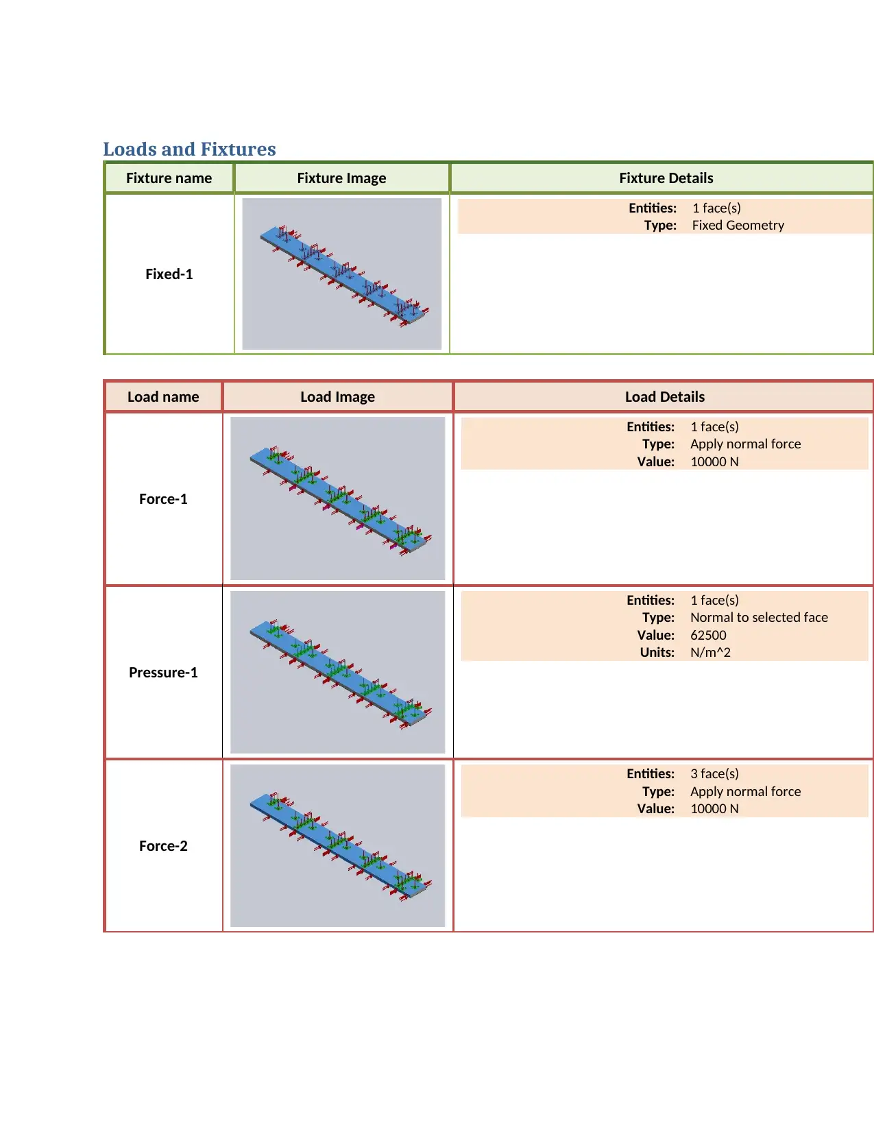
Loads and Fixtures
Fixture name Fixture Image Fixture Details
Fixed-1
Entities: 1 face(s)
Type: Fixed Geometry
Load name Load Image Load Details
Force-1
Entities: 1 face(s)
Type: Apply normal force
Value: 10000 N
Pressure-1
Entities: 1 face(s)
Type: Normal to selected face
Value: 62500
Units: N/m^2
Force-2
Entities: 3 face(s)
Type: Apply normal force
Value: 10000 N
Paraphrase This Document
Need a fresh take? Get an instant paraphrase of this document with our AI Paraphraser
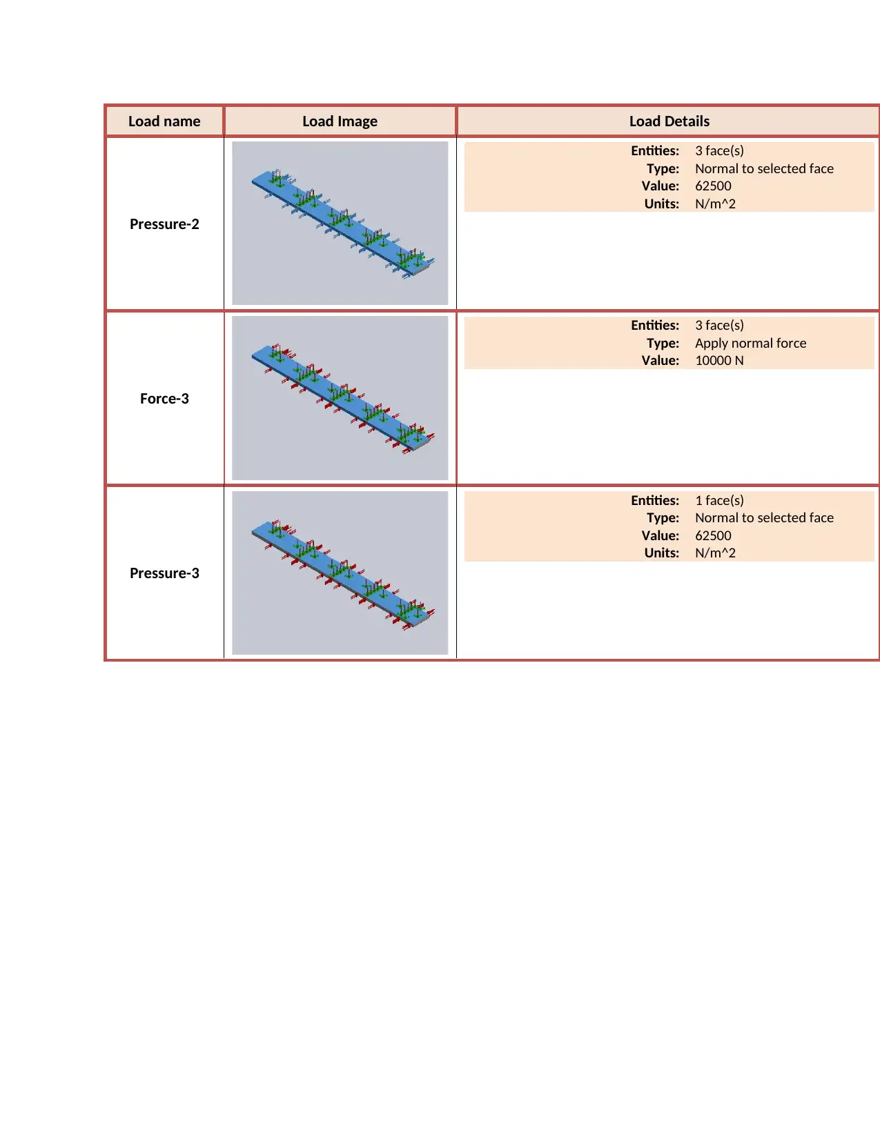
Load name Load Image Load Details
Pressure-2
Entities: 3 face(s)
Type: Normal to selected face
Value: 62500
Units: N/m^2
Force-3
Entities: 3 face(s)
Type: Apply normal force
Value: 10000 N
Pressure-3
Entities: 1 face(s)
Type: Normal to selected face
Value: 62500
Units: N/m^2
Pressure-2
Entities: 3 face(s)
Type: Normal to selected face
Value: 62500
Units: N/m^2
Force-3
Entities: 3 face(s)
Type: Apply normal force
Value: 10000 N
Pressure-3
Entities: 1 face(s)
Type: Normal to selected face
Value: 62500
Units: N/m^2
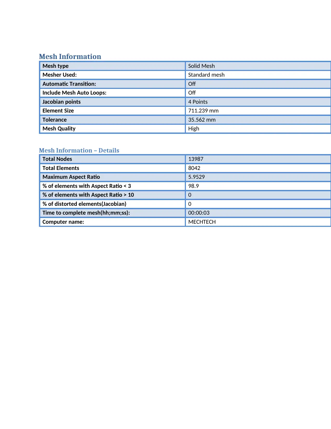
Mesh Information
Mesh type Solid Mesh
Mesher Used: Standard mesh
Automatic Transition: Off
Include Mesh Auto Loops: Off
Jacobian points 4 Points
Element Size 711.239 mm
Tolerance 35.562 mm
Mesh Quality High
Mesh Information – Details
Total Nodes 13987
Total Elements 8042
Maximum Aspect Ratio 5.9529
% of elements with Aspect Ratio < 3 98.9
% of elements with Aspect Ratio > 10 0
% of distorted elements(Jacobian) 0
Time to complete mesh(hh;mm;ss): 00:00:03
Computer name: MECHTECH
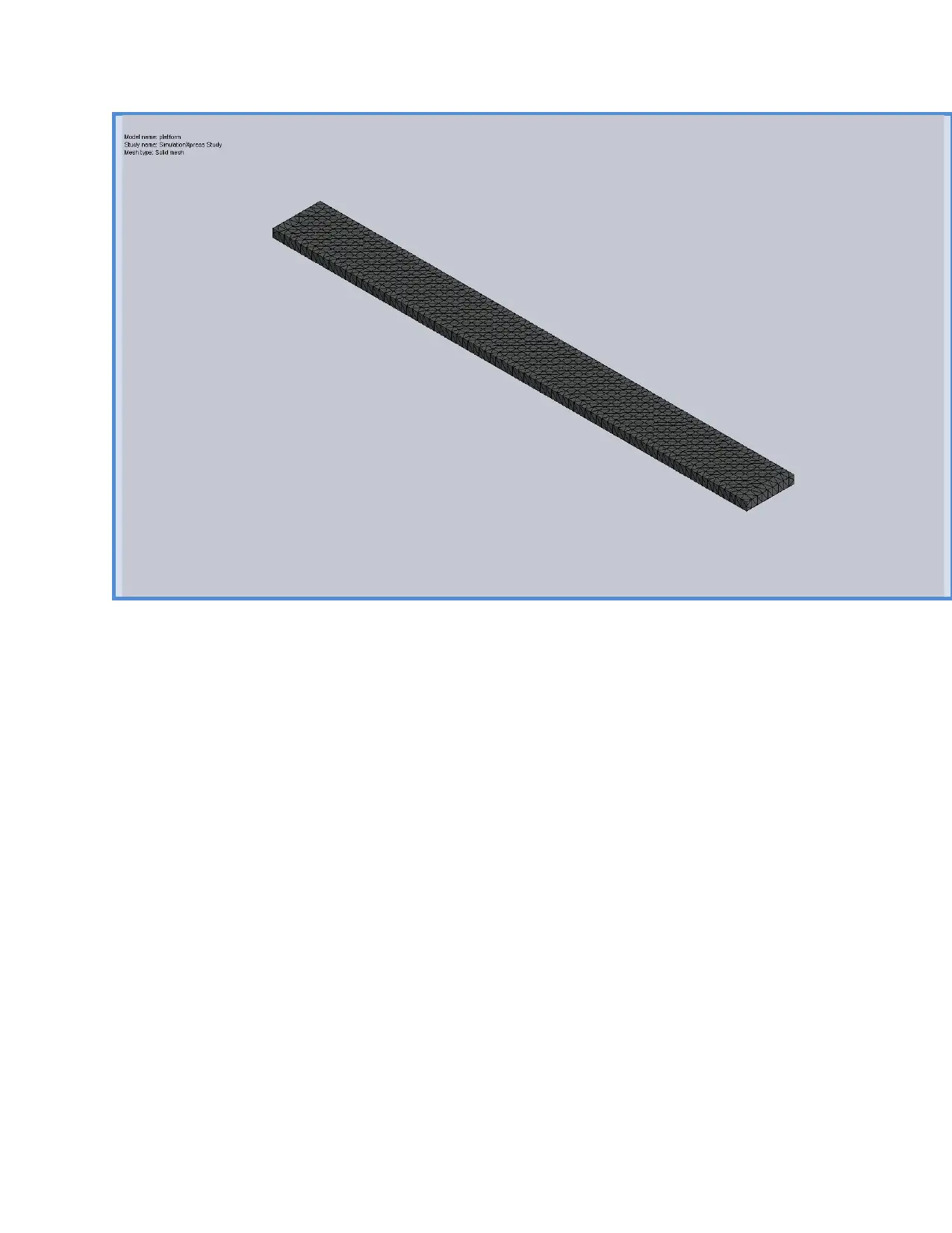
Secure Best Marks with AI Grader
Need help grading? Try our AI Grader for instant feedback on your assignments.
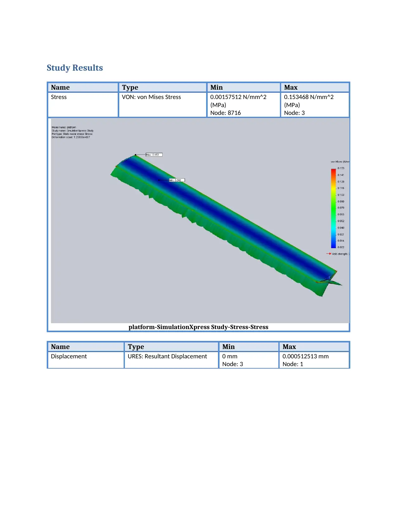
Study Results
Name Type Min Max
Stress VON: von Mises Stress 0.00157512 N/mm^2
(MPa)
Node: 8716
0.153468 N/mm^2
(MPa)
Node: 3
platform-SimulationXpress Study-Stress-Stress
Name Type Min Max
Displacement URES: Resultant Displacement 0 mm
Node: 3
0.000512513 mm
Node: 1
Name Type Min Max
Stress VON: von Mises Stress 0.00157512 N/mm^2
(MPa)
Node: 8716
0.153468 N/mm^2
(MPa)
Node: 3
platform-SimulationXpress Study-Stress-Stress
Name Type Min Max
Displacement URES: Resultant Displacement 0 mm
Node: 3
0.000512513 mm
Node: 1
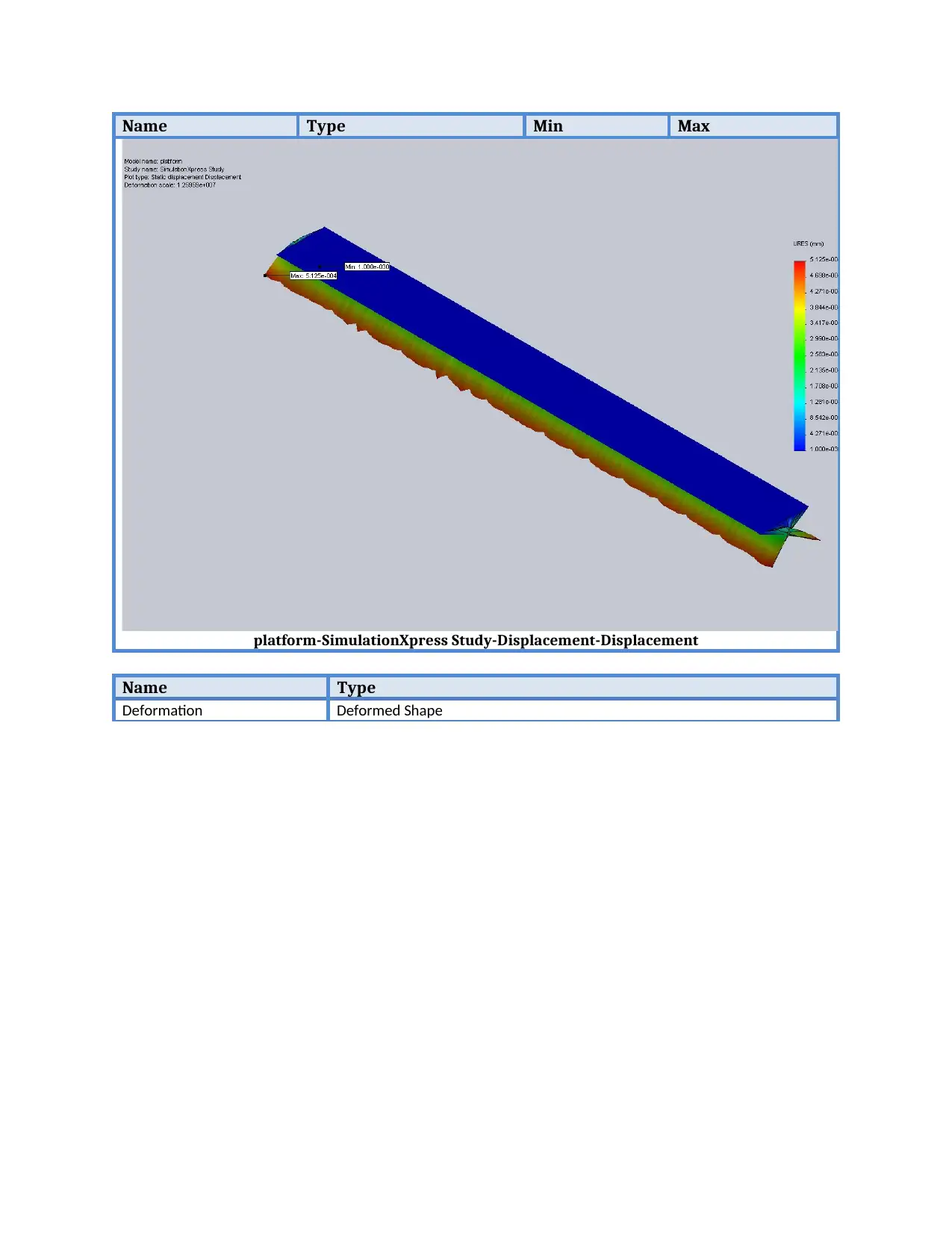
Name Type Min Max
platform-SimulationXpress Study-Displacement-Displacement
Name Type
Deformation Deformed Shape
platform-SimulationXpress Study-Displacement-Displacement
Name Type
Deformation Deformed Shape
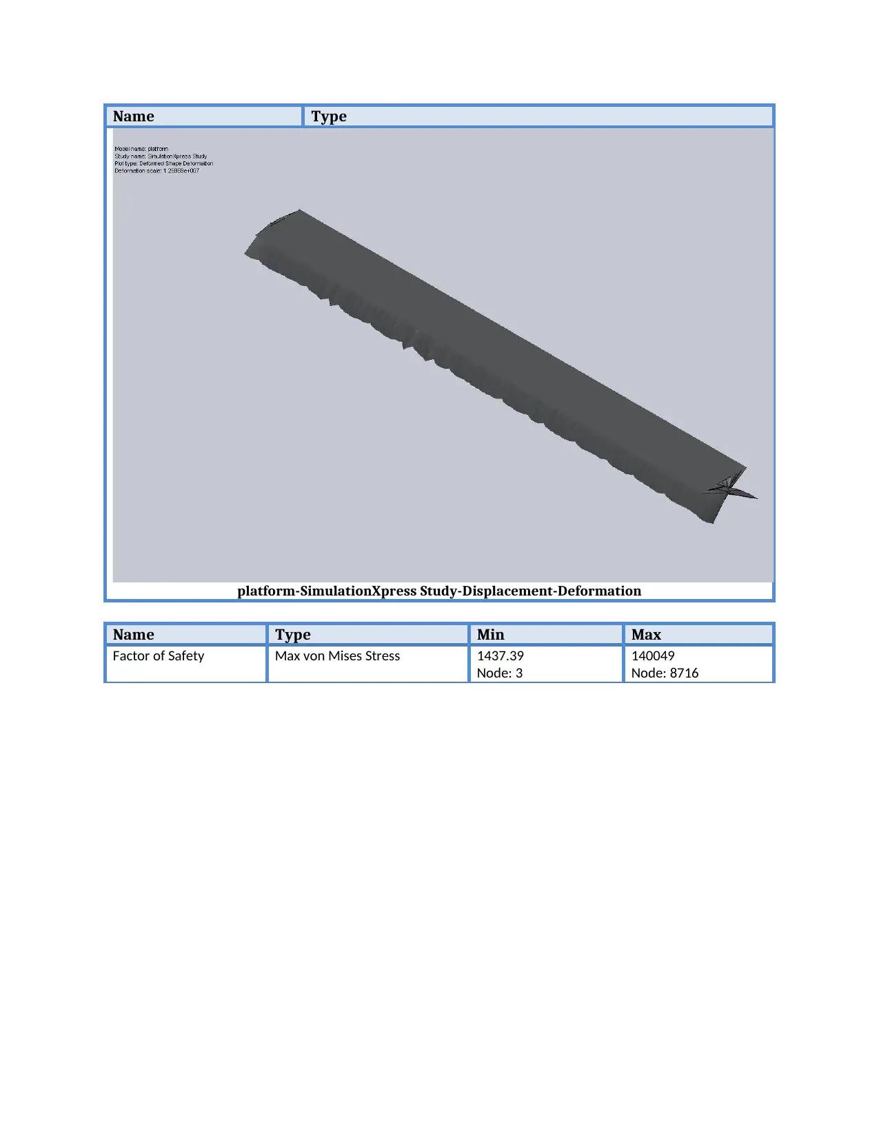
Name Type
platform-SimulationXpress Study-Displacement-Deformation
Name Type Min Max
Factor of Safety Max von Mises Stress 1437.39
Node: 3
140049
Node: 8716
platform-SimulationXpress Study-Displacement-Deformation
Name Type Min Max
Factor of Safety Max von Mises Stress 1437.39
Node: 3
140049
Node: 8716
Paraphrase This Document
Need a fresh take? Get an instant paraphrase of this document with our AI Paraphraser
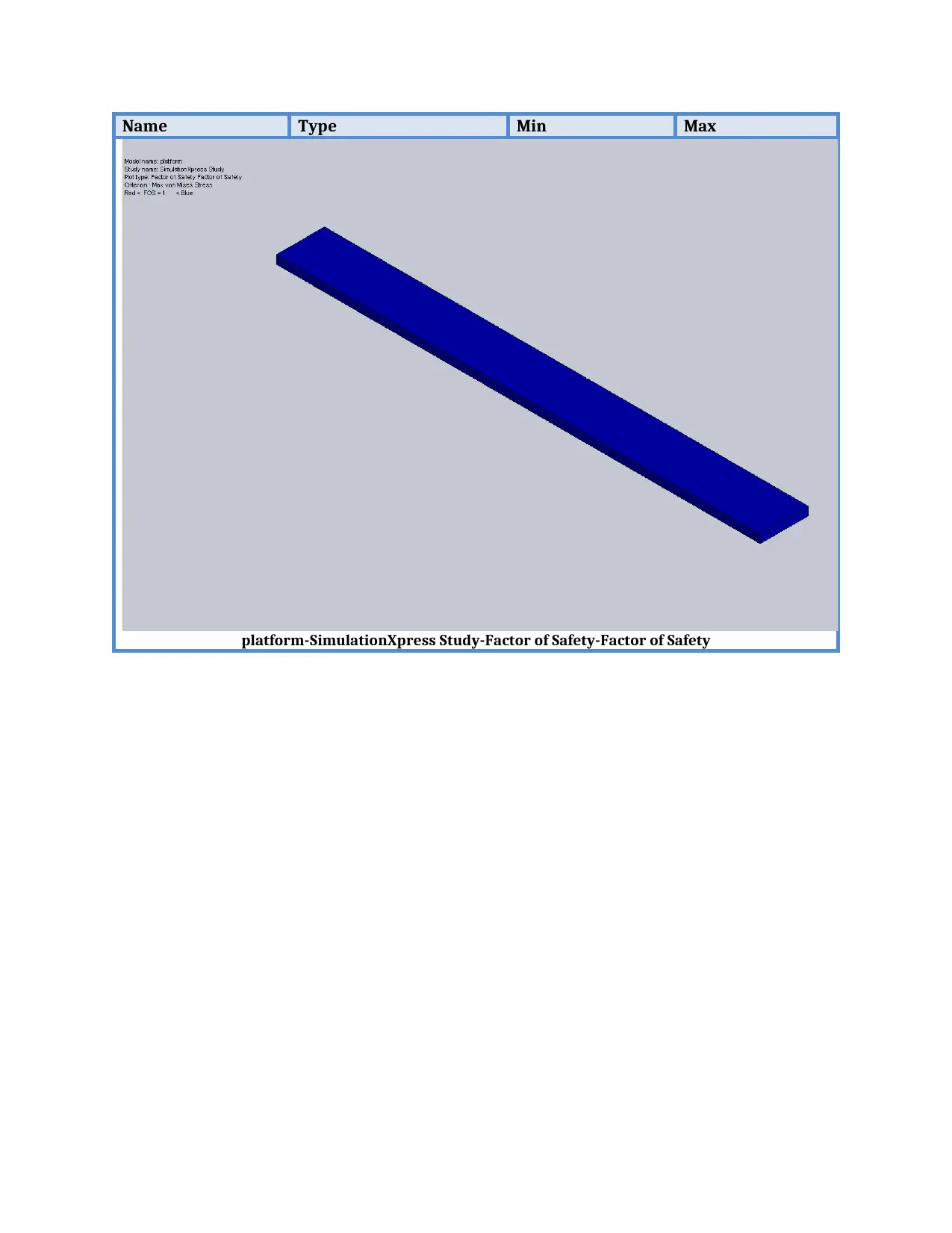
Name Type Min Max
platform-SimulationXpress Study-Factor of Safety-Factor of Safety
platform-SimulationXpress Study-Factor of Safety-Factor of Safety

Simulation of cable 2
Date: Wednesday, October 31, 2018
Designer: Madhav
Study name: SimulationXpress Study
Analysis type: Static
Table of Contents
Assumptions...............................................................2
Model Information.....................................................2
Material Properties....................................................3
Loads and Fixtures......................................................4
Mesh Information.......................................................5
Study Results..............................................................7

Assumptions
Secure Best Marks with AI Grader
Need help grading? Try our AI Grader for instant feedback on your assignments.
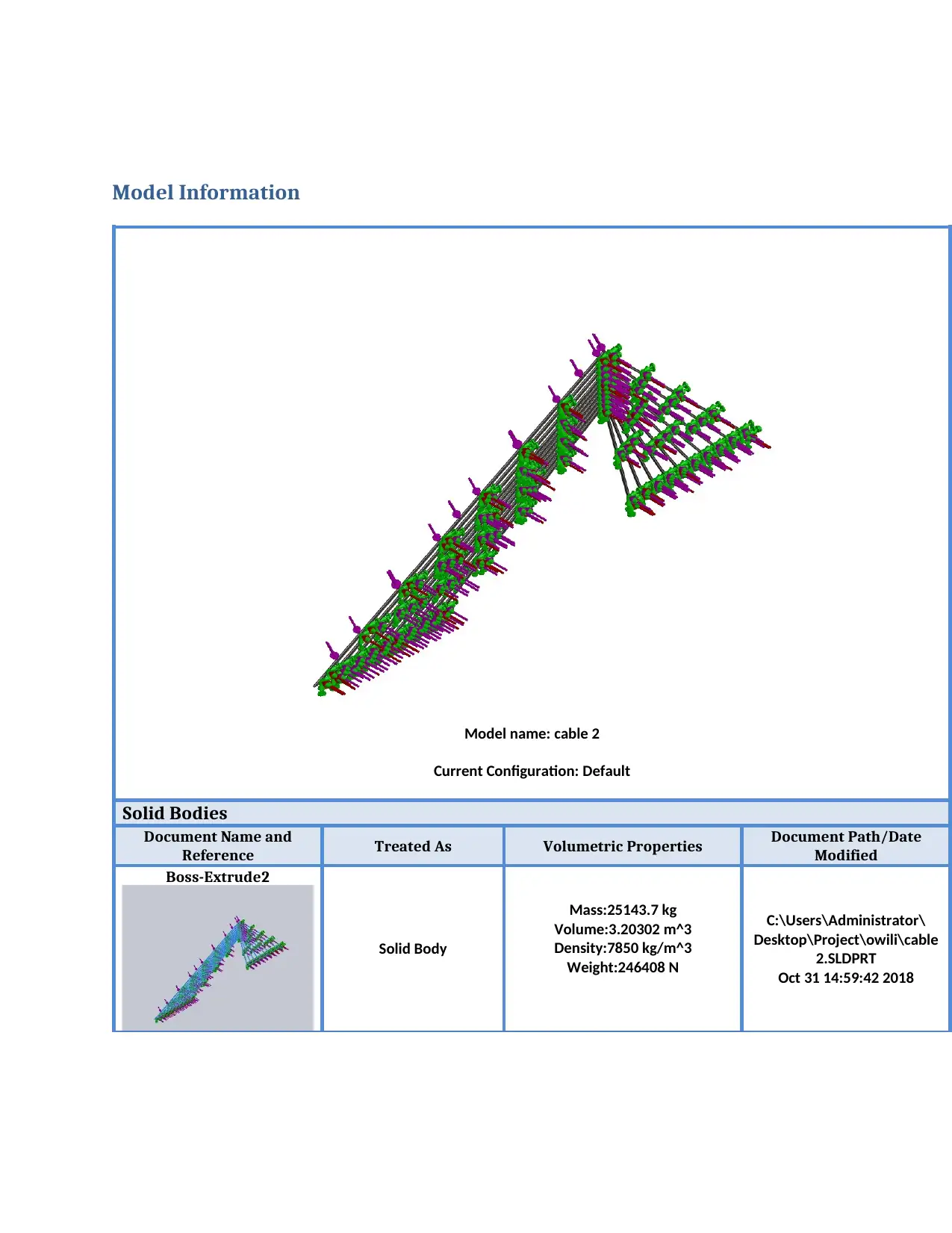
Model Information
Model name: cable 2
Current Configuration: Default
Solid Bodies
Document Name and
Reference Treated As Volumetric Properties Document Path/Date
Modified
Boss-Extrude2
Solid Body
Mass:25143.7 kg
Volume:3.20302 m^3
Density:7850 kg/m^3
Weight:246408 N
C:\Users\Administrator\
Desktop\Project\owili\cable
2.SLDPRT
Oct 31 14:59:42 2018
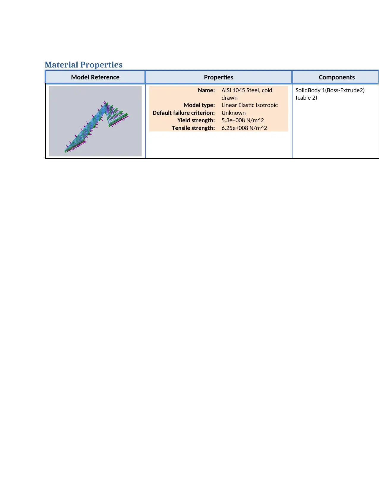
Material Properties
Model Reference Properties Components
Name: AISI 1045 Steel, cold
drawn
Model type: Linear Elastic Isotropic
Default failure criterion: Unknown
Yield strength: 5.3e+008 N/m^2
Tensile strength: 6.25e+008 N/m^2
SolidBody 1(Boss-Extrude2)
(cable 2)
Model Reference Properties Components
Name: AISI 1045 Steel, cold
drawn
Model type: Linear Elastic Isotropic
Default failure criterion: Unknown
Yield strength: 5.3e+008 N/m^2
Tensile strength: 6.25e+008 N/m^2
SolidBody 1(Boss-Extrude2)
(cable 2)
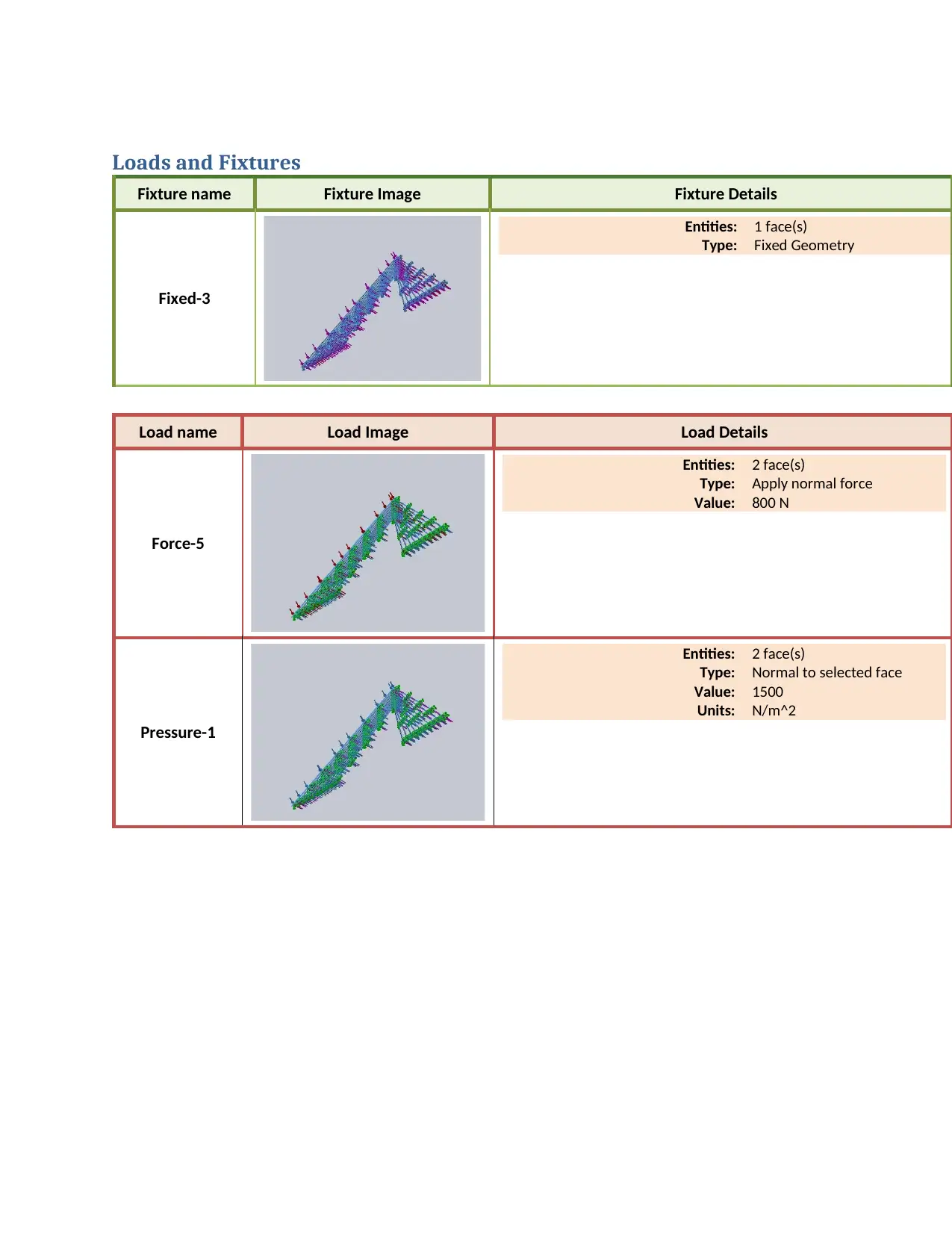
Loads and Fixtures
Fixture name Fixture Image Fixture Details
Fixed-3
Entities: 1 face(s)
Type: Fixed Geometry
Load name Load Image Load Details
Force-5
Entities: 2 face(s)
Type: Apply normal force
Value: 800 N
Pressure-1
Entities: 2 face(s)
Type: Normal to selected face
Value: 1500
Units: N/m^2
Fixture name Fixture Image Fixture Details
Fixed-3
Entities: 1 face(s)
Type: Fixed Geometry
Load name Load Image Load Details
Force-5
Entities: 2 face(s)
Type: Apply normal force
Value: 800 N
Pressure-1
Entities: 2 face(s)
Type: Normal to selected face
Value: 1500
Units: N/m^2
Paraphrase This Document
Need a fresh take? Get an instant paraphrase of this document with our AI Paraphraser
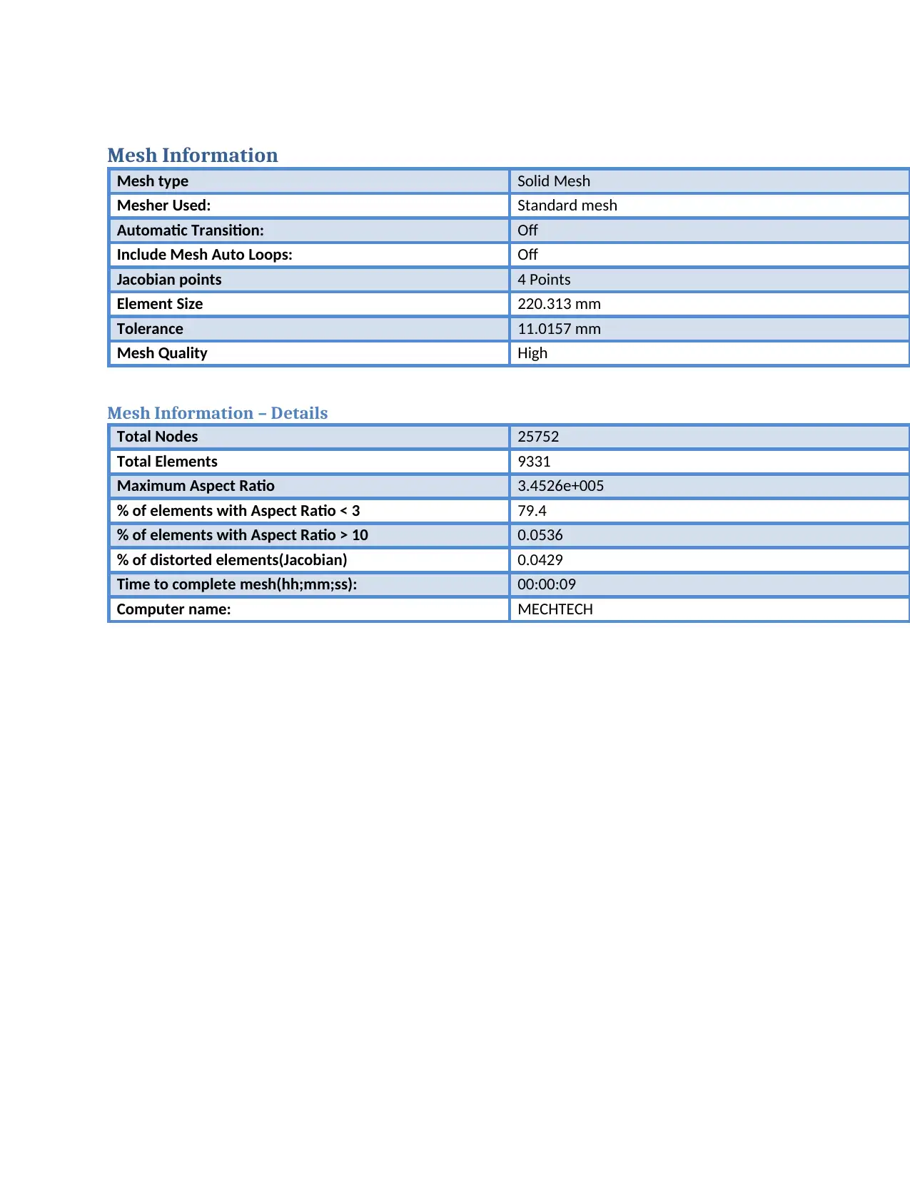
Mesh Information
Mesh type Solid Mesh
Mesher Used: Standard mesh
Automatic Transition: Off
Include Mesh Auto Loops: Off
Jacobian points 4 Points
Element Size 220.313 mm
Tolerance 11.0157 mm
Mesh Quality High
Mesh Information – Details
Total Nodes 25752
Total Elements 9331
Maximum Aspect Ratio 3.4526e+005
% of elements with Aspect Ratio < 3 79.4
% of elements with Aspect Ratio > 10 0.0536
% of distorted elements(Jacobian) 0.0429
Time to complete mesh(hh;mm;ss): 00:00:09
Computer name: MECHTECH
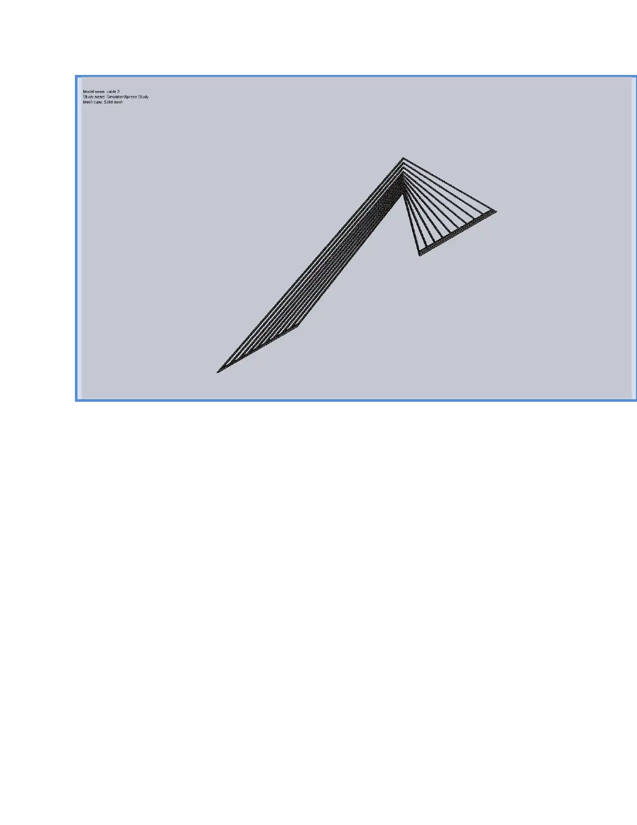
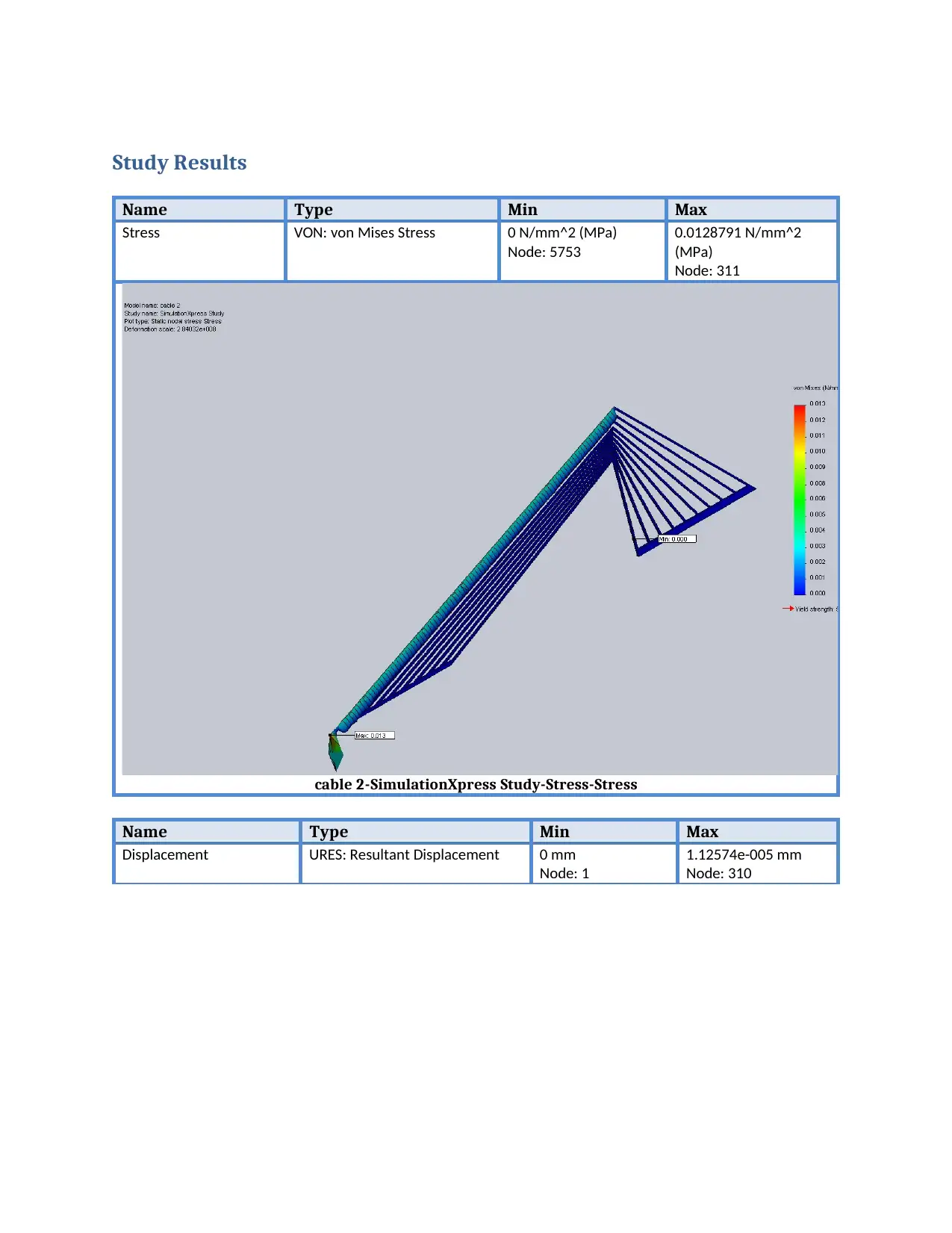
Study Results
Name Type Min Max
Stress VON: von Mises Stress 0 N/mm^2 (MPa)
Node: 5753
0.0128791 N/mm^2
(MPa)
Node: 311
cable 2-SimulationXpress Study-Stress-Stress
Name Type Min Max
Displacement URES: Resultant Displacement 0 mm
Node: 1
1.12574e-005 mm
Node: 310
Name Type Min Max
Stress VON: von Mises Stress 0 N/mm^2 (MPa)
Node: 5753
0.0128791 N/mm^2
(MPa)
Node: 311
cable 2-SimulationXpress Study-Stress-Stress
Name Type Min Max
Displacement URES: Resultant Displacement 0 mm
Node: 1
1.12574e-005 mm
Node: 310
Secure Best Marks with AI Grader
Need help grading? Try our AI Grader for instant feedback on your assignments.
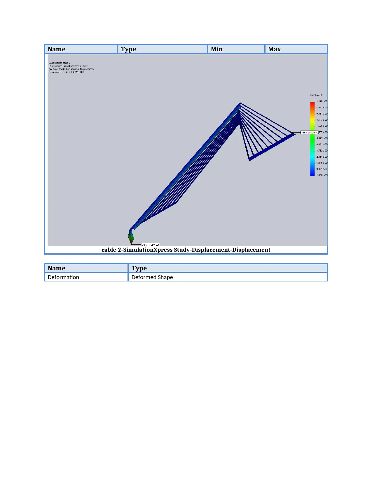
Name Type Min Max
cable 2-SimulationXpress Study-Displacement-Displacement
Name Type
Deformation Deformed Shape
cable 2-SimulationXpress Study-Displacement-Displacement
Name Type
Deformation Deformed Shape
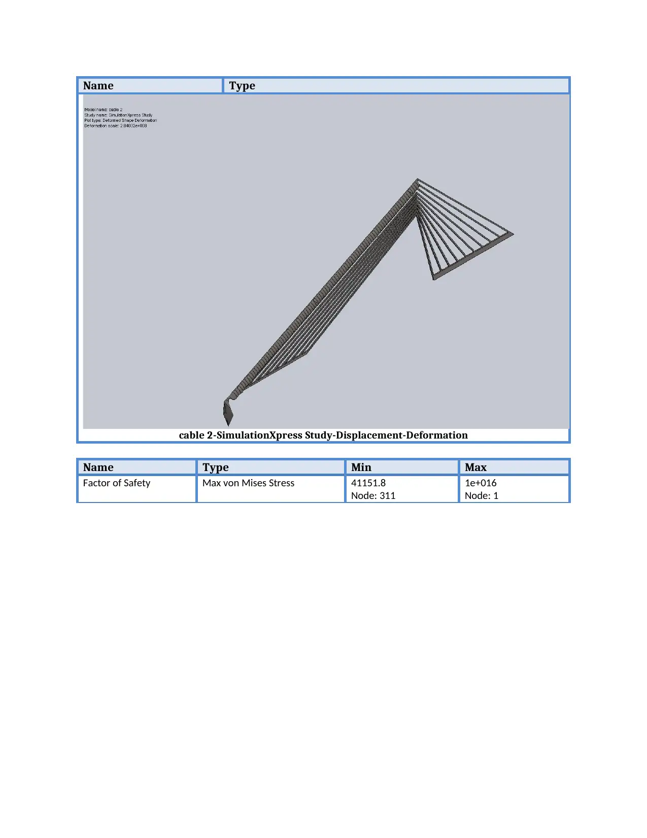
Name Type
cable 2-SimulationXpress Study-Displacement-Deformation
Name Type Min Max
Factor of Safety Max von Mises Stress 41151.8
Node: 311
1e+016
Node: 1
cable 2-SimulationXpress Study-Displacement-Deformation
Name Type Min Max
Factor of Safety Max von Mises Stress 41151.8
Node: 311
1e+016
Node: 1
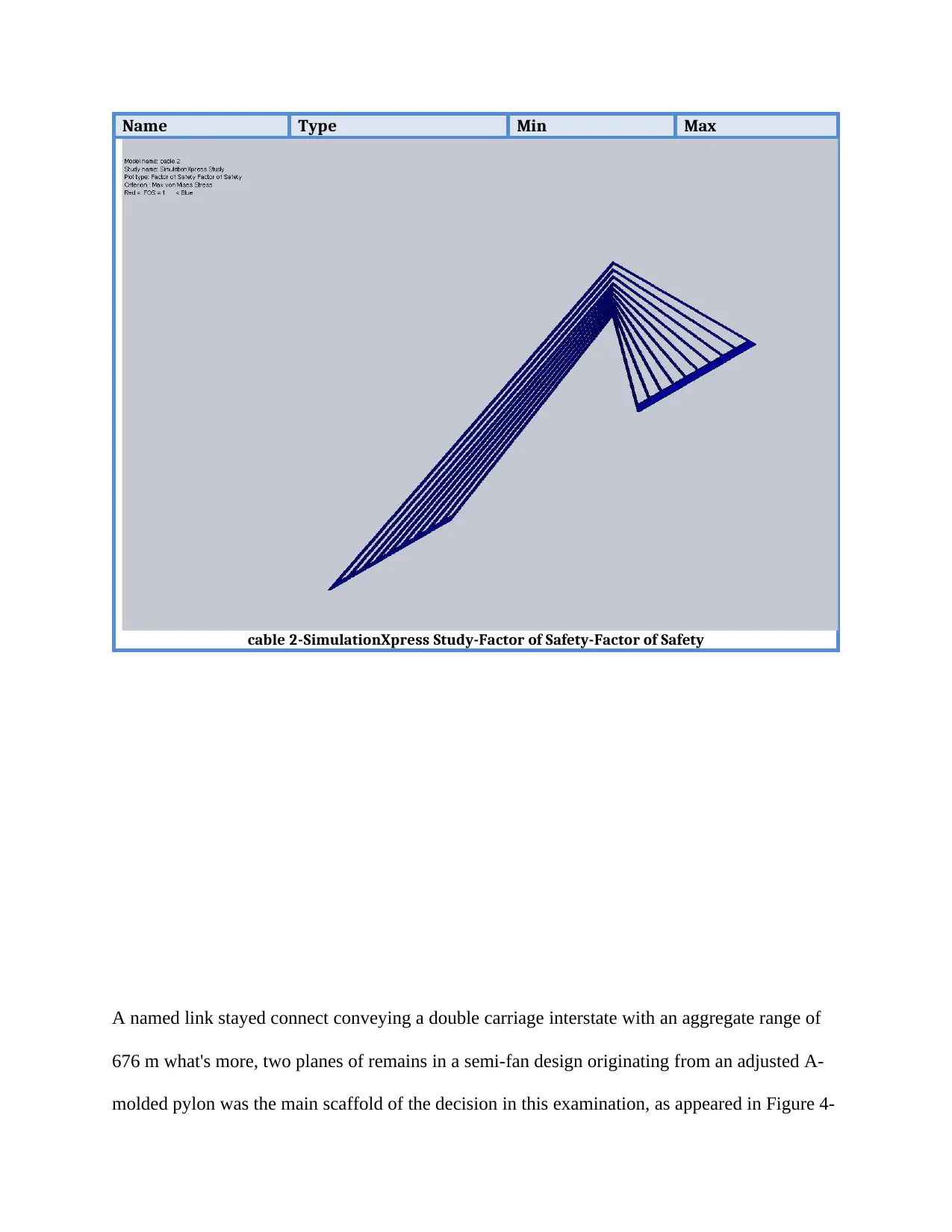
Name Type Min Max
cable 2-SimulationXpress Study-Factor of Safety-Factor of Safety
A named link stayed connect conveying a double carriage interstate with an aggregate range of
676 m what's more, two planes of remains in a semi-fan design originating from an adjusted A-
molded pylon was the main scaffold of the decision in this examination, as appeared in Figure 4-
Paraphrase This Document
Need a fresh take? Get an instant paraphrase of this document with our AI Paraphraser
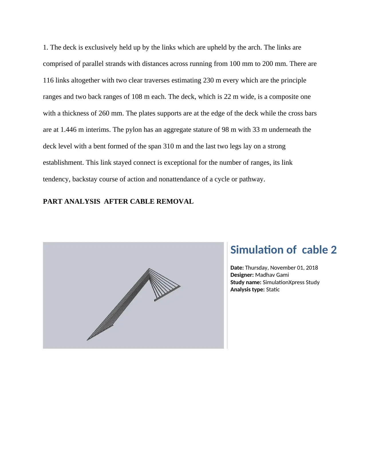
1. The deck is exclusively held up by the links which are upheld by the arch. The links are
comprised of parallel strands with distances across running from 100 mm to 200 mm. There are
116 links altogether with two clear traverses estimating 230 m every which are the principle
ranges and two back ranges of 108 m each. The deck, which is 22 m wide, is a composite one
with a thickness of 260 mm. The plates supports are at the edge of the deck while the cross bars
are at 1.446 m interims. The pylon has an aggregate stature of 98 m with 33 m underneath the
deck level with a bent formed of the span 310 m and the last two legs lay on a strong
establishment. This link stayed connect is exceptional for the number of ranges, its link
tendency, backstay course of action and nonattendance of a cycle or pathway.
PART ANALYSIS AFTER CABLE REMOVAL
Simulation of cable 2
Date: Thursday, November 01, 2018
Designer: Madhav Gami
Study name: SimulationXpress Study
Analysis type: Static

Table of Contents
Assumptions...............................................................2
Model Information.....................................................2
Material Properties....................................................3
Loads and Fixtures......................................................4
Mesh Information.......................................................6
Study Results..............................................................8

Assumptions
Secure Best Marks with AI Grader
Need help grading? Try our AI Grader for instant feedback on your assignments.
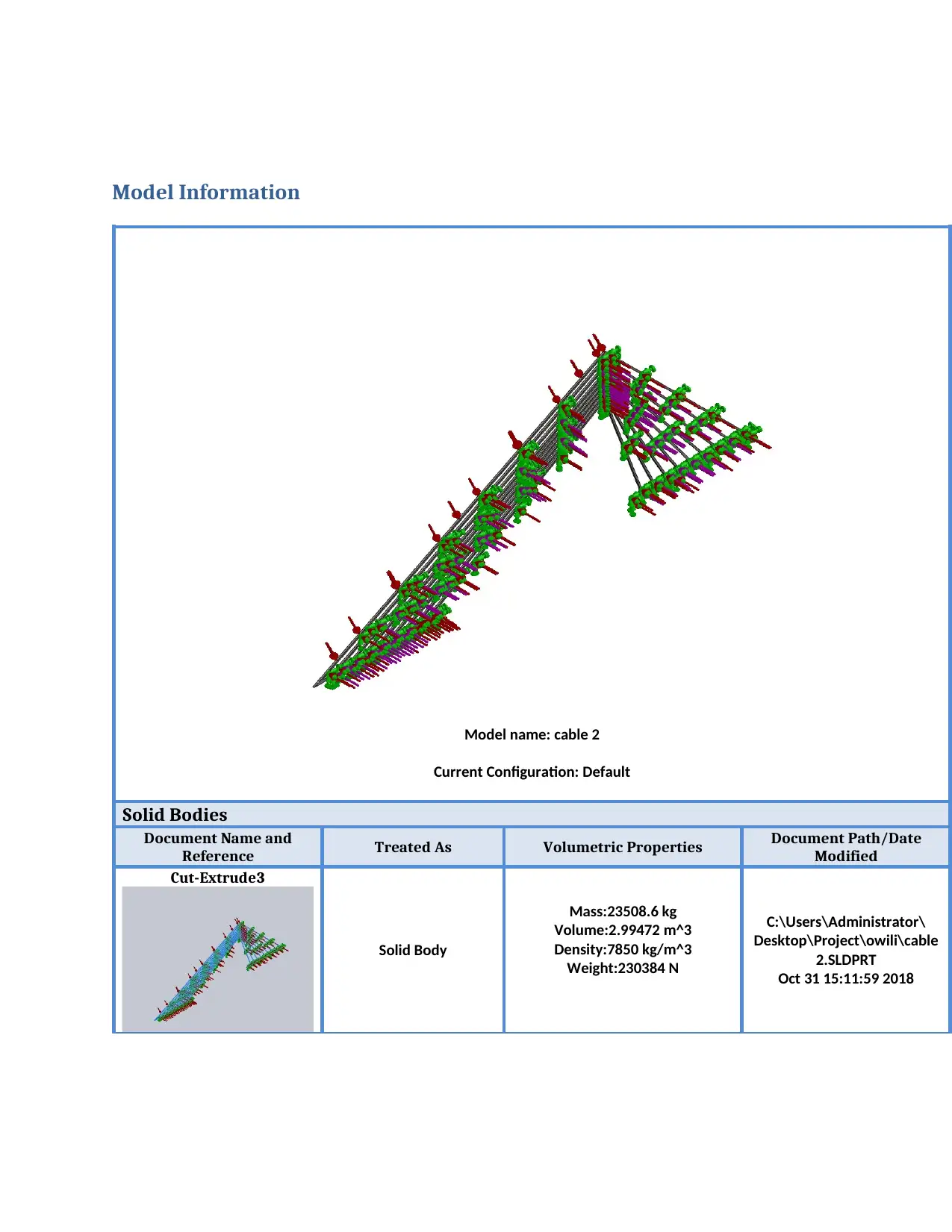
Model Information
Model name: cable 2
Current Configuration: Default
Solid Bodies
Document Name and
Reference Treated As Volumetric Properties Document Path/Date
Modified
Cut-Extrude3
Solid Body
Mass:23508.6 kg
Volume:2.99472 m^3
Density:7850 kg/m^3
Weight:230384 N
C:\Users\Administrator\
Desktop\Project\owili\cable
2.SLDPRT
Oct 31 15:11:59 2018
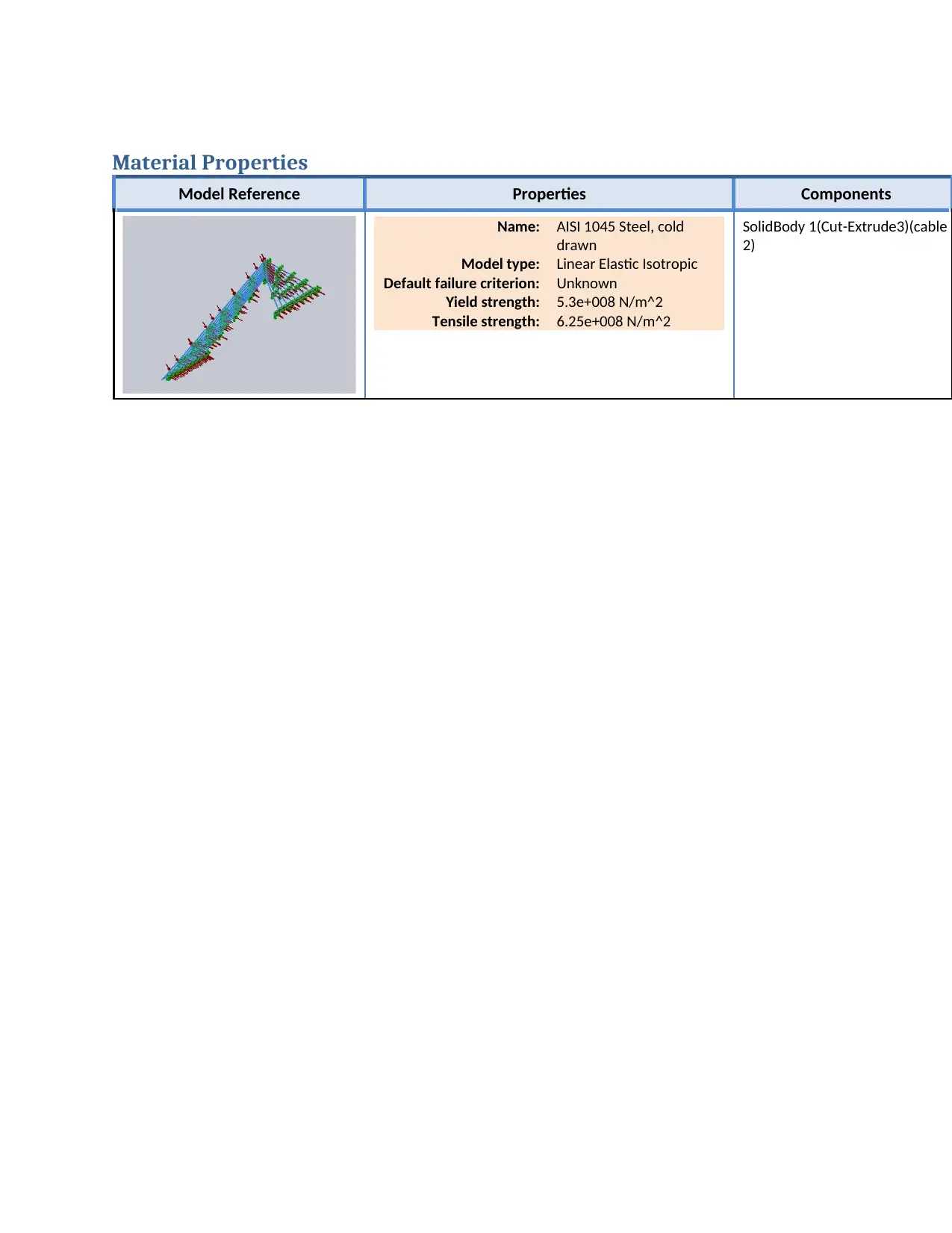
Material Properties
Model Reference Properties Components
Name: AISI 1045 Steel, cold
drawn
Model type: Linear Elastic Isotropic
Default failure criterion: Unknown
Yield strength: 5.3e+008 N/m^2
Tensile strength: 6.25e+008 N/m^2
SolidBody 1(Cut-Extrude3)(cable
2)
Model Reference Properties Components
Name: AISI 1045 Steel, cold
drawn
Model type: Linear Elastic Isotropic
Default failure criterion: Unknown
Yield strength: 5.3e+008 N/m^2
Tensile strength: 6.25e+008 N/m^2
SolidBody 1(Cut-Extrude3)(cable
2)
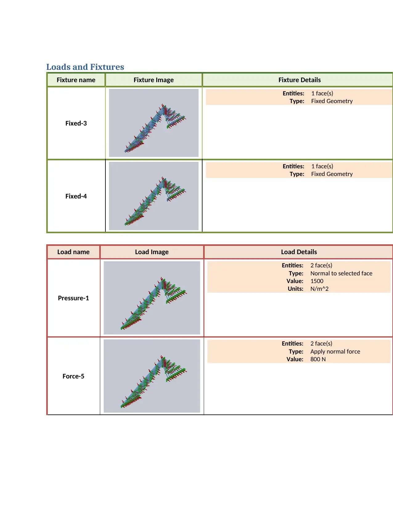
Loads and Fixtures
Fixture name Fixture Image Fixture Details
Fixed-3
Entities: 1 face(s)
Type: Fixed Geometry
Fixed-4
Entities: 1 face(s)
Type: Fixed Geometry
Load name Load Image Load Details
Pressure-1
Entities: 2 face(s)
Type: Normal to selected face
Value: 1500
Units: N/m^2
Force-5
Entities: 2 face(s)
Type: Apply normal force
Value: 800 N
Paraphrase This Document
Need a fresh take? Get an instant paraphrase of this document with our AI Paraphraser
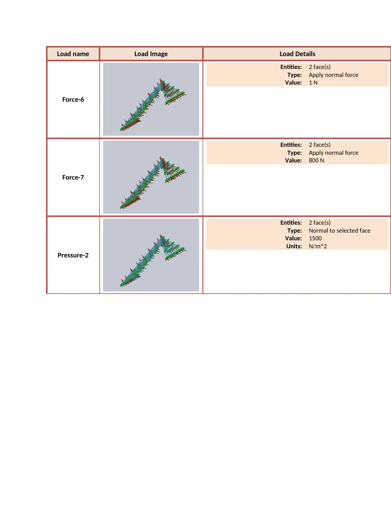
Load name Load Image Load Details
Force-6
Entities: 2 face(s)
Type: Apply normal force
Value: 1 N
Force-7
Entities: 2 face(s)
Type: Apply normal force
Value: 800 N
Pressure-2
Entities: 2 face(s)
Type: Normal to selected face
Value: 1500
Units: N/m^2
Force-6
Entities: 2 face(s)
Type: Apply normal force
Value: 1 N
Force-7
Entities: 2 face(s)
Type: Apply normal force
Value: 800 N
Pressure-2
Entities: 2 face(s)
Type: Normal to selected face
Value: 1500
Units: N/m^2

Mesh Information
Mesh type Solid Mesh
Mesher Used: Standard mesh
Automatic Transition: Off
Include Mesh Auto Loops: Off
Jacobian points 4 Points
Element Size 220.313 mm
Tolerance 11.0157 mm
Mesh Quality High
Mesh Information – Details
Total Nodes 24105
Total Elements 8786
Maximum Aspect Ratio 47.456
% of elements with Aspect Ratio < 3 79.5
% of elements with Aspect Ratio > 10 0.0114
% of distorted elements(Jacobian) 0.0114
Time to complete mesh(hh;mm;ss): 00:00:11
Computer name: MECHTECH
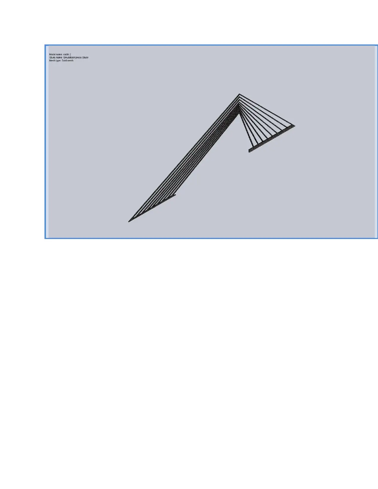
Secure Best Marks with AI Grader
Need help grading? Try our AI Grader for instant feedback on your assignments.
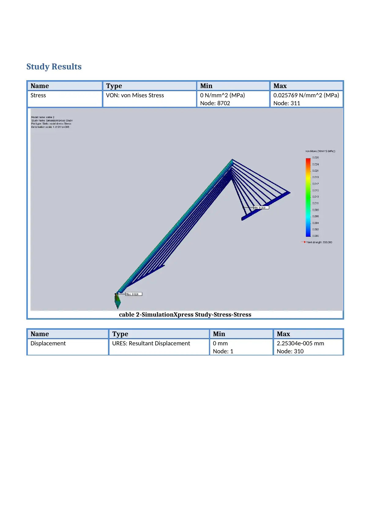
Study Results
Name Type Min Max
Stress VON: von Mises Stress 0 N/mm^2 (MPa)
Node: 8702
0.025769 N/mm^2 (MPa)
Node: 311
cable 2-SimulationXpress Study-Stress-Stress
Name Type Min Max
Displacement URES: Resultant Displacement 0 mm
Node: 1
2.25304e-005 mm
Node: 310
Name Type Min Max
Stress VON: von Mises Stress 0 N/mm^2 (MPa)
Node: 8702
0.025769 N/mm^2 (MPa)
Node: 311
cable 2-SimulationXpress Study-Stress-Stress
Name Type Min Max
Displacement URES: Resultant Displacement 0 mm
Node: 1
2.25304e-005 mm
Node: 310
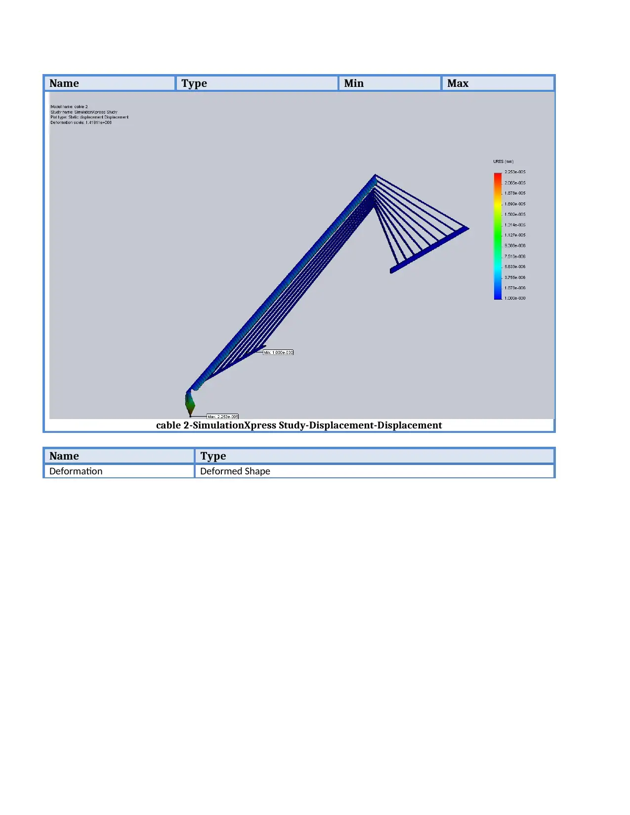
Name Type Min Max
cable 2-SimulationXpress Study-Displacement-Displacement
Name Type
Deformation Deformed Shape
cable 2-SimulationXpress Study-Displacement-Displacement
Name Type
Deformation Deformed Shape
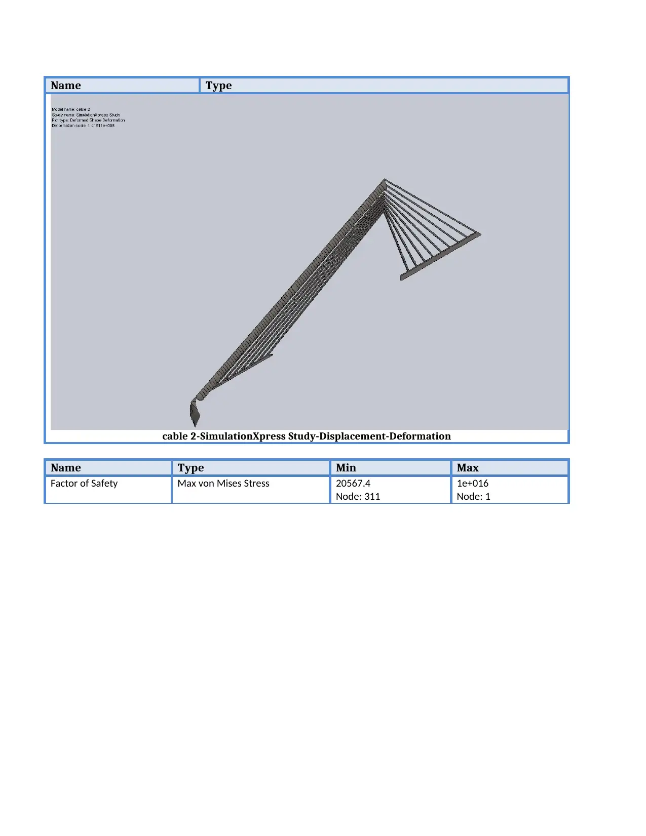
Name Type
cable 2-SimulationXpress Study-Displacement-Deformation
Name Type Min Max
Factor of Safety Max von Mises Stress 20567.4
Node: 311
1e+016
Node: 1
cable 2-SimulationXpress Study-Displacement-Deformation
Name Type Min Max
Factor of Safety Max von Mises Stress 20567.4
Node: 311
1e+016
Node: 1
Paraphrase This Document
Need a fresh take? Get an instant paraphrase of this document with our AI Paraphraser
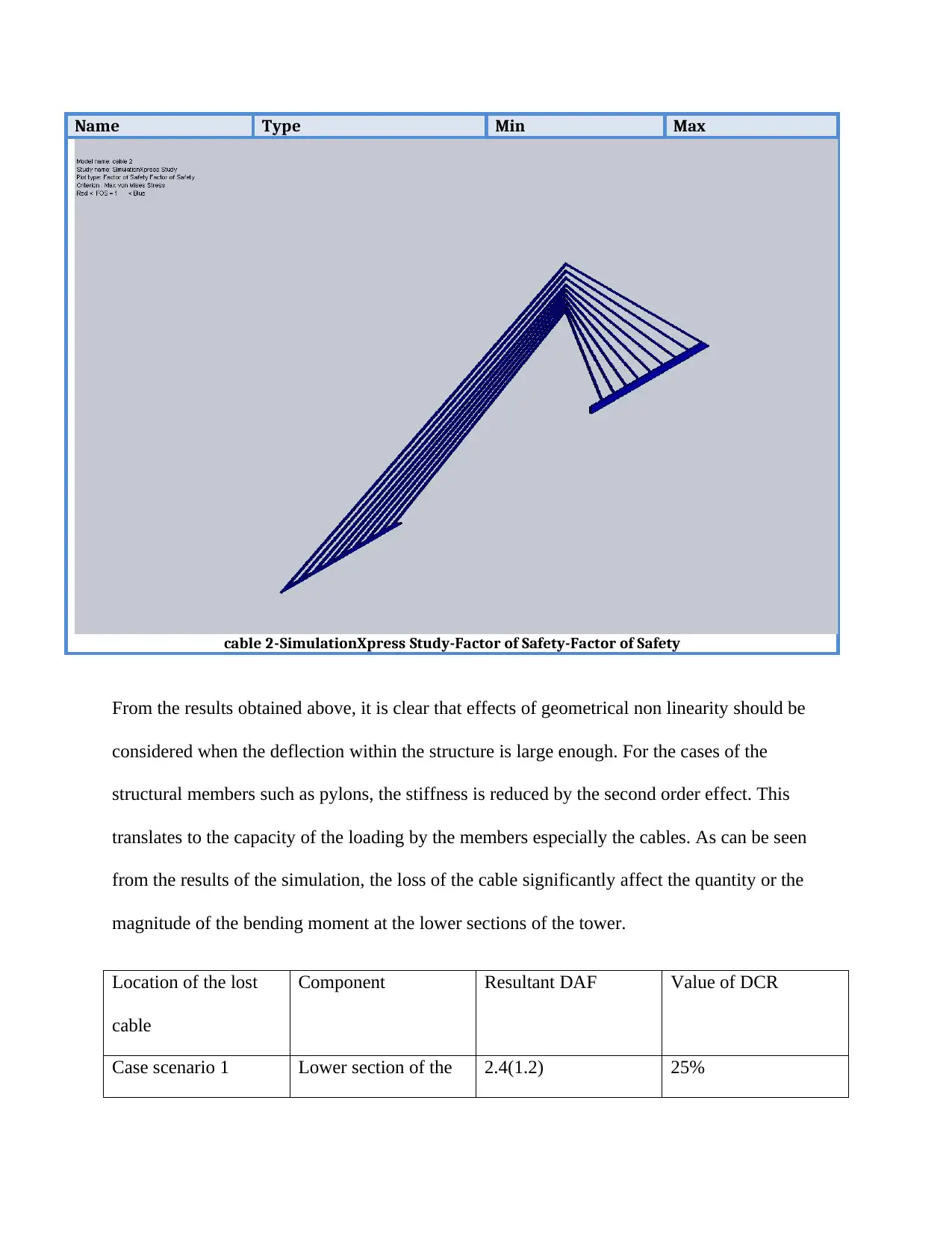
Name Type Min Max
cable 2-SimulationXpress Study-Factor of Safety-Factor of Safety
From the results obtained above, it is clear that effects of geometrical non linearity should be
considered when the deflection within the structure is large enough. For the cases of the
structural members such as pylons, the stiffness is reduced by the second order effect. This
translates to the capacity of the loading by the members especially the cables. As can be seen
from the results of the simulation, the loss of the cable significantly affect the quantity or the
magnitude of the bending moment at the lower sections of the tower.
Location of the lost
cable
Component Resultant DAF Value of DCR
Case scenario 1 Lower section of the 2.4(1.2) 25%
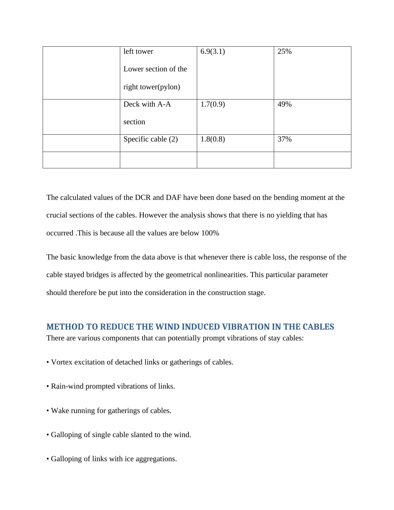
left tower
Lower section of the
right tower(pylon)
6.9(3.1) 25%
Deck with A-A
section
1.7(0.9) 49%
Specific cable (2) 1.8(0.8) 37%
The calculated values of the DCR and DAF have been done based on the bending moment at the
crucial sections of the cables. However the analysis shows that there is no yielding that has
occurred .This is because all the values are below 100%
The basic knowledge from the data above is that whenever there is cable loss, the response of the
cable stayed bridges is affected by the geometrical nonlinearities. This particular parameter
should therefore be put into the consideration in the construction stage.
METHOD TO REDUCE THE WIND INDUCED VIBRATION IN THE CABLES
There are various components that can potentially prompt vibrations of stay cables:
• Vortex excitation of detached links or gatherings of cables.
• Rain-wind prompted vibrations of links.
• Wake running for gatherings of cables.
• Galloping of single cable slanted to the wind.
• Galloping of links with ice aggregations.
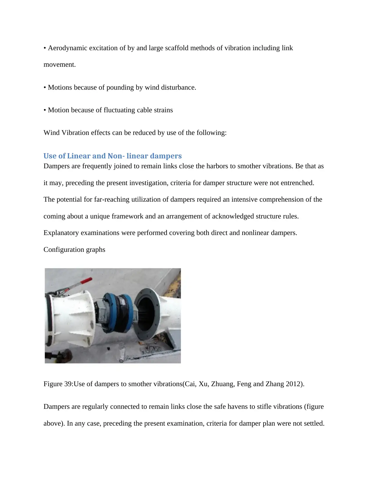
• Aerodynamic excitation of by and large scaffold methods of vibration including link
movement.
• Motions because of pounding by wind disturbance.
• Motion because of fluctuating cable strains
Wind Vibration effects can be reduced by use of the following:
Use of Linear and Non- linear dampers
Dampers are frequently joined to remain links close the harbors to smother vibrations. Be that as
it may, preceding the present investigation, criteria for damper structure were not entrenched.
The potential for far-reaching utilization of dampers required an intensive comprehension of the
coming about a unique framework and an arrangement of acknowledged structure rules.
Explanatory examinations were performed covering both direct and nonlinear dampers.
Configuration graphs
Figure 39:Use of dampers to smother vibrations(Cai, Xu, Zhuang, Feng and Zhang 2012).
Dampers are regularly connected to remain links close the safe havens to stifle vibrations (figure
above). In any case, preceding the present examination, criteria for damper plan were not settled.
Secure Best Marks with AI Grader
Need help grading? Try our AI Grader for instant feedback on your assignments.
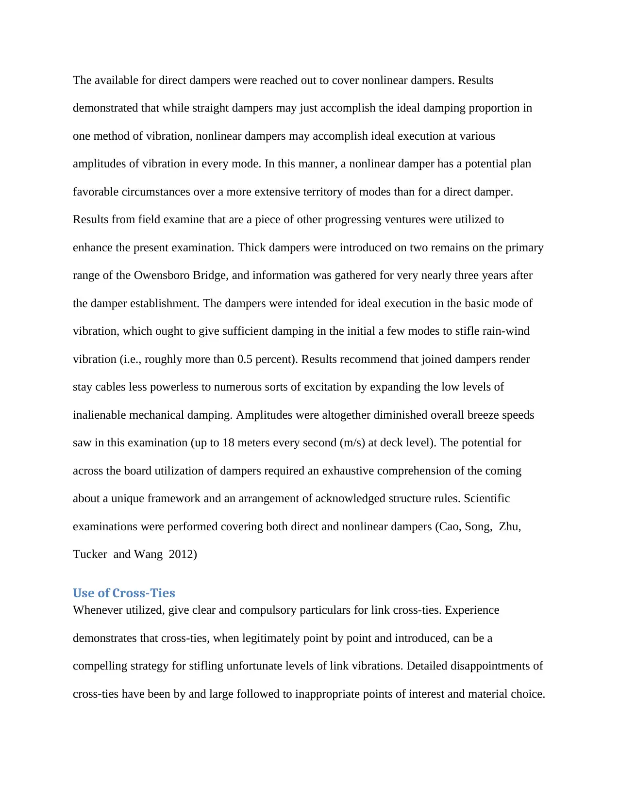
The available for direct dampers were reached out to cover nonlinear dampers. Results
demonstrated that while straight dampers may just accomplish the ideal damping proportion in
one method of vibration, nonlinear dampers may accomplish ideal execution at various
amplitudes of vibration in every mode. In this manner, a nonlinear damper has a potential plan
favorable circumstances over a more extensive territory of modes than for a direct damper.
Results from field examine that are a piece of other progressing ventures were utilized to
enhance the present examination. Thick dampers were introduced on two remains on the primary
range of the Owensboro Bridge, and information was gathered for very nearly three years after
the damper establishment. The dampers were intended for ideal execution in the basic mode of
vibration, which ought to give sufficient damping in the initial a few modes to stifle rain-wind
vibration (i.e., roughly more than 0.5 percent). Results recommend that joined dampers render
stay cables less powerless to numerous sorts of excitation by expanding the low levels of
inalienable mechanical damping. Amplitudes were altogether diminished overall breeze speeds
saw in this examination (up to 18 meters every second (m/s) at deck level). The potential for
across the board utilization of dampers required an exhaustive comprehension of the coming
about a unique framework and an arrangement of acknowledged structure rules. Scientific
examinations were performed covering both direct and nonlinear dampers (Cao, Song, Zhu,
Tucker and Wang 2012)
Use of Cross-Ties
Whenever utilized, give clear and compulsory particulars for link cross-ties. Experience
demonstrates that cross-ties, when legitimately point by point and introduced, can be a
compelling strategy for stifling unfortunate levels of link vibrations. Detailed disappointments of
cross-ties have been by and large followed to inappropriate points of interest and material choice.
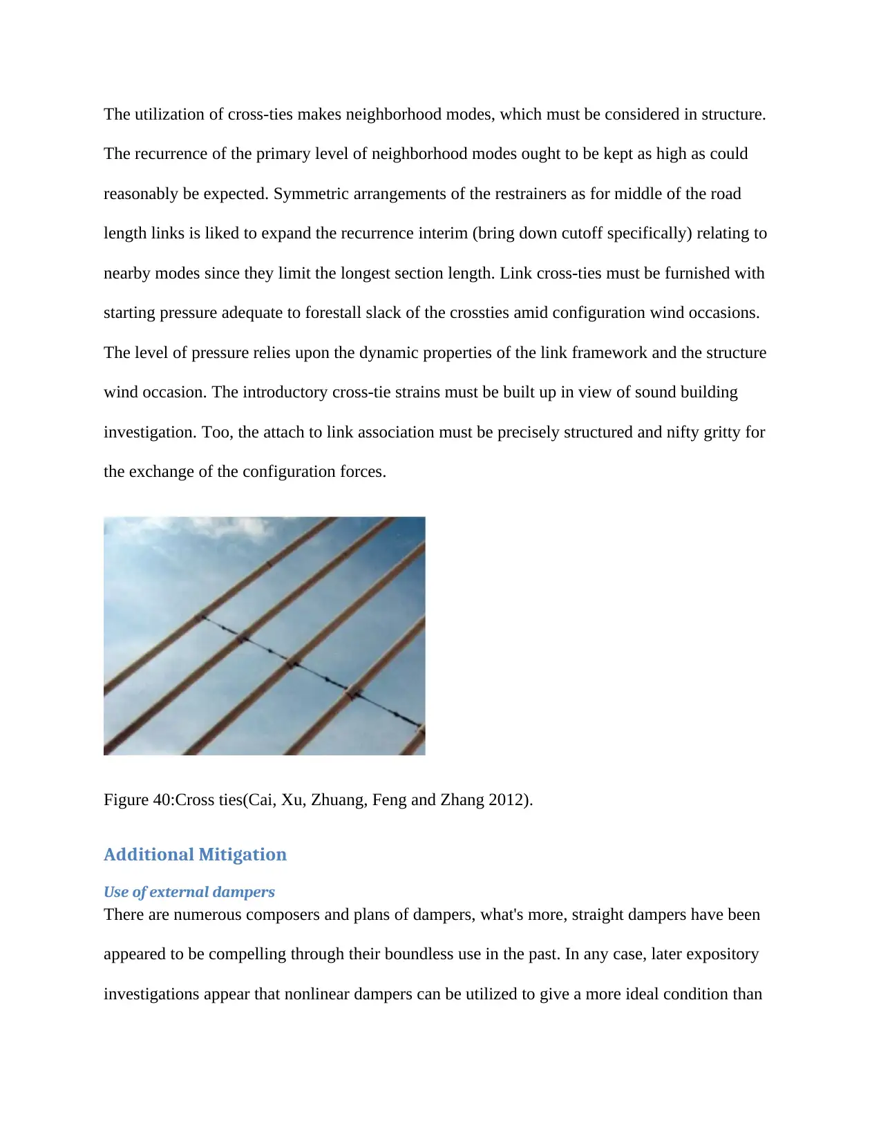
The utilization of cross-ties makes neighborhood modes, which must be considered in structure.
The recurrence of the primary level of neighborhood modes ought to be kept as high as could
reasonably be expected. Symmetric arrangements of the restrainers as for middle of the road
length links is liked to expand the recurrence interim (bring down cutoff specifically) relating to
nearby modes since they limit the longest section length. Link cross-ties must be furnished with
starting pressure adequate to forestall slack of the crossties amid configuration wind occasions.
The level of pressure relies upon the dynamic properties of the link framework and the structure
wind occasion. The introductory cross-tie strains must be built up in view of sound building
investigation. Too, the attach to link association must be precisely structured and nifty gritty for
the exchange of the configuration forces.
Figure 40:Cross ties(Cai, Xu, Zhuang, Feng and Zhang 2012).
Additional Mitigation
Use of external dampers
There are numerous composers and plans of dampers, what's more, straight dampers have been
appeared to be compelling through their boundless use in the past. In any case, later expository
investigations appear that nonlinear dampers can be utilized to give a more ideal condition than
straight dampers, as these are viable over a bigger scope of modes. Specifically, the damping
execution of square-foot dampers (β=0.5) is autonomous of the model number and is just
influenced by the adequacy of vibration. With a few dampers, (for example, dashpot type), a
beginning static erosion compel must be survived prior to connecting with of the gooey
component. Field tests have demonstrated the nearness of this stick-move-stick-move conduct
related to such dampers. This may successfully give a settled hub rather than the expected
damping for the link at low adequacy motions, and ought to be considered in the plan. The visco-
flexible type dampers where an elastomeric component is forever connected between the link
and the supporting components, hypothetically, are free of such introductory frictional limits. On
the other hand, there are likewise damper plans that depend on grating as the vitality scattering
instrument furthermore; the static erosion limit for such dampers might be higher than for
alternate sorts. As the greater part of the watched movement because of rain-wind vibrations is in
the vertical course, it might be adequate to give damping against just the vertical movement. In
any case, this has not been plainly set up. It is suggested that damping is made compelling
against link development in any heading. Damper mounting points of interest may exchange
horizontal powers because of damper activity onto segments of the link jetty. Such powers must
be considered in the structure of the link docks.
ECONOMIC ANALYSIS
The cost estimate of the bridge was done as per the current market price of the components of the
bridge.
Component of the bridge Estimated cost of the structure in USD
Paraphrase This Document
Need a fresh take? Get an instant paraphrase of this document with our AI Paraphraser
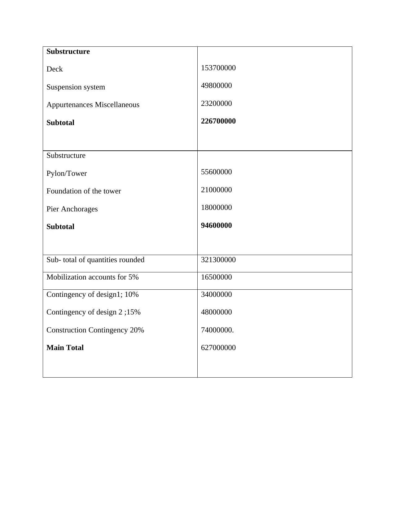
Substructure
Deck
Suspension system
Appurtenances Miscellaneous
Subtotal
153700000
49800000
23200000
226700000
Substructure
Pylon/Tower
Foundation of the tower
Pier Anchorages
Subtotal
55600000
21000000
18000000
94600000
Sub- total of quantities rounded 321300000
Mobilization accounts for 5% 16500000
Contingency of design1; 10%
Contingency of design 2 ;15%
Construction Contingency 20%
Main Total
34000000
48000000
74000000.
627000000
CONCLUSION AND RECOMMENDATIONS
Owensboro Bridge interfaces the Rockport and Kentucky over the Indiana Ohio River. Taking
into account that the length of the range was expanded and also more shallow and slim solidness,
the braces were utilized in the advanced link stayed spans. There are a lot of essential issues that
might be considered in the assessment of the plan. It has turned out to be exceptionally critical to
legitimately comprehend and furthermore foresee the loadings that front diverse reactions. The
investigation that has been led by and by spotlights on the standard displaying of the Owensboro
Bridge. It has been shown that the elements based procedures of the assessment typically gives
the worldwide method to be utilized in the testing of auxiliary properties.
The elements basic assessment typically puts some type of enhancement in the base of the
instrumentation. Alternate exercises that should be given consideration in such tasks incorporate
the information obtaining, display refreshing, and assessment of the structure lastly setting of the
calculation for the distinguishing proof of the framework. The utilization of the limited
component model can be viably utilized for the evaluation of the wellbeing status of the
extension or the structure later on.
The entire arrangement of the 3D nonlinear displaying of the link of the stayed scaffold has
really been found to especially difficult. The discretization of the littler qualities would be hard
when such figures are viewed as wasteful and to a great degree vast. There is regularly no
certification that such extensive numbers will join thinking about that they are nonlinear.
Because of the hanging of the link, the static examination of the link is ordinarily viewed as
geometric nonlinear. In both the static investigation and the dynamic examination, the weight on
the link that is regularly called pressure solidifying will be geometrically nonlinear.
At the point when the nonlinear investigation is managed without the focused on hardening, the
outcome will be proportionate to the prematurely ended run. This is a result of the disparate
wavering. This specific impact will be so regardless of the way that removal intermingling
paradigm is connected(Soyluk and Sicacik 2012). There has been an exhibition of the huge
relocations that prompt the impediment of the impacts of the powers. The redirection of the deck
can just occur under the dead heaps of the extension. After the presentation of the huge endure
the underlying stage inside the link. The static avoidance investigation of the Owensboro connect
link delivered little diversion. Note that the pressure hardening is regularly required when the
point of the movement is to produce the concurrent arrangement. The underlying strain that was
found inside the links was viewed as the key factors in the control of the underlying principles
that are required for the arrangement
Such arrangements are ordinarily accomplished under the dead loads. In the instances of the
entire scaffold, the verifiable truth is that the first position of the link and the extension itself
faces redirection in their shapes. The conduct of the scaffold will be dictated by the dead loads.
The first parity of the setup of the extension was because of the dead loads. The accomplishment
of such impacts will be through the plans of the scaffold that was given at first (Cai, Xu, Zhuang,
Feng and Zhang 2012).
The outcomes that have been acquired obviously show that this kind of the scaffold is an
exceedingly squeezed structure. The impact of oneself weight on the execution of the extension
can viably be utilized to decide the soundness of the structure. The modular or the dynamic
investigation should dependably begin from the first purpose of the design because of the dead
loads. This investigation should consolidate the two stages that will incorporate the little
avoidance static examination that is situated underneath the dead loads the second step ought to
Secure Best Marks with AI Grader
Need help grading? Try our AI Grader for instant feedback on your assignments.
incorporate pre-focused on examination of the model that will additionally incorporate the
solidness of the part.
It has been seen that one of the commanded methods of the Owensboro link stayed connect must
be consolidated with different modes too to take into account the best possible usefulness. It has
been seen that the horizontal solidness of the link stayed extension will be even significantly
more grounded. This specific data uncovers the parallel firmness of the parts of the utilized link
was observed to be substantially more grounded .From the investigations of the parameter, it was
found that the vertical modular qualities of the materials that issue most incorporate link of the
sectional region, the mass, vertical bowing of the deck lastly link versatile modulus. The real
parameters that influence the torsional modular properties and the transverse attributes are the
equivalent as the limit conditions.
The free vibration testing gives a quick technique to acquire the genuine powerful attributes of
the extension. The modular parameters can be acquired from the testing of the dynamic just by
the utilization of the pinnacle picking strategy. This specific strategy is viewed as proficient and
quick. There was no legitimate coordinating of the states of the transverse course thinking about
that the scaffold was hardened in this specific bearing. Likewise, the transverse excitation was
difficult to be shifted from the information of the commotion. A legitimate relationship was built
up between the adjusted limited component show and the in situ free vibration testing. The best
possible coordinating for the higher modes isn't really anticipated that would radiate from the
estimations of the yield estimation. The adjusted gauge can be utilized as the reference point for
the investigation of the extension later on. The set up relationship was imperative for checking
the status of the Owensboro Bridge.
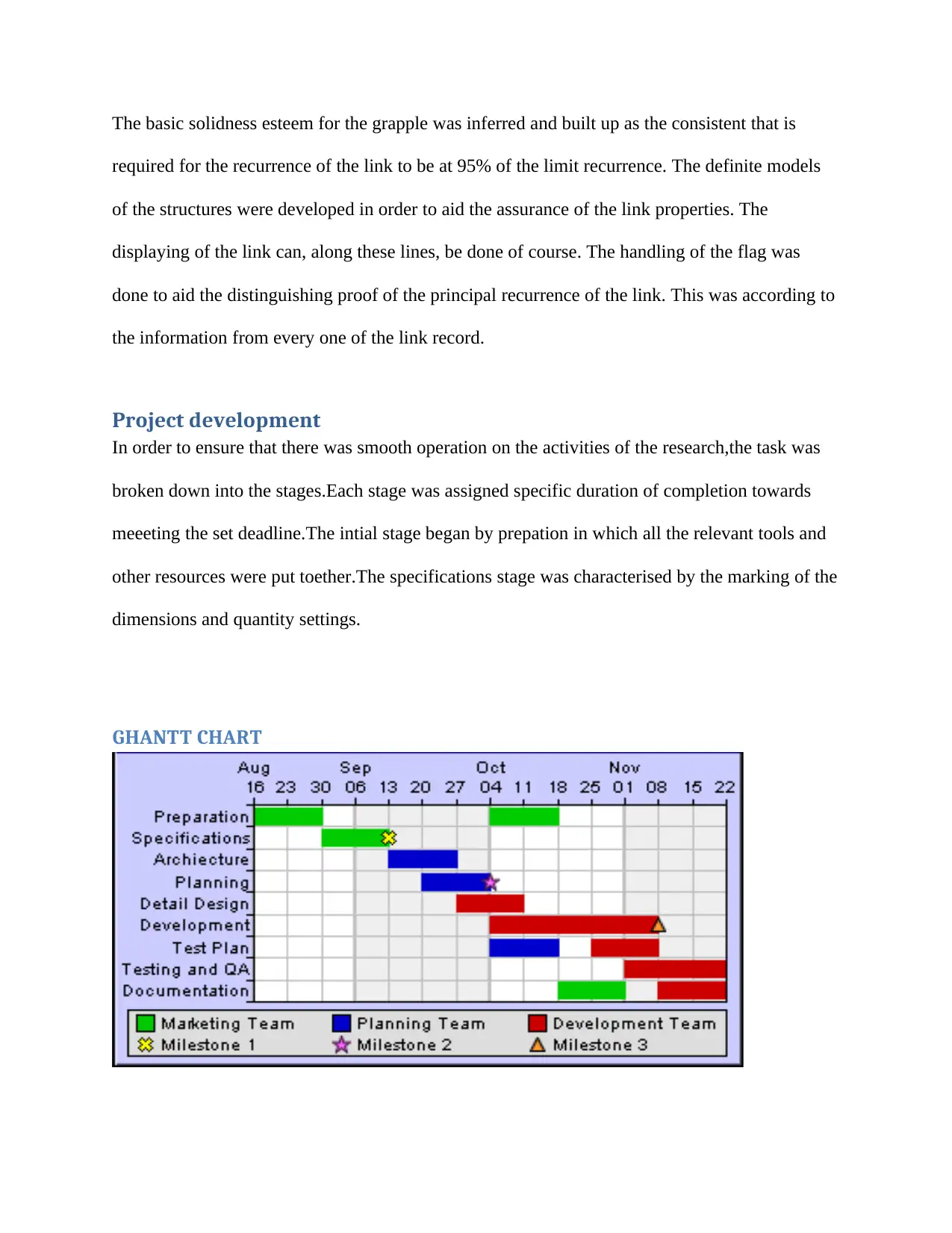
The basic solidness esteem for the grapple was inferred and built up as the consistent that is
required for the recurrence of the link to be at 95% of the limit recurrence. The definite models
of the structures were developed in order to aid the assurance of the link properties. The
displaying of the link can, along these lines, be done of course. The handling of the flag was
done to aid the distinguishing proof of the principal recurrence of the link. This was according to
the information from every one of the link record.
Project development
In order to ensure that there was smooth operation on the activities of the research,the task was
broken down into the stages.Each stage was assigned specific duration of completion towards
meeeting the set deadline.The intial stage began by prepation in which all the relevant tools and
other resources were put toether.The specifications stage was characterised by the marking of the
dimensions and quantity settings.
GHANTT CHART

REFERENCES
Cai, J.G., Xu, Y.X., Zhuang, L.P., Feng, J. and Zhang, J., 2012. Comparison of various
procedures for progressive collapse analysis of cable-stayed bridges. Journal of Zhejiang
University SCIENCE A, 13(5), pp.323-334.
Cao, D.Q., Song, M.T., Zhu, W.D., Tucker, R.W. and Wang, C.T., 2012. Modeling and analysis
of the in-plane vibration of a complex cable-stayed bridge. Journal of Sound and
Vibration, 331(26), pp.5685-5714.
CAO, S.S., LEI, J.Q., LI, Z.S., LIN, D.J. and WANG, R.G., 2012. Analysis of Rigidity of Multi-
Pylon Cable-Stayed Bridges [J]. World Bridges, 1, p.014.
Domaneschi, M. and Martinelli, L., 2012. Performance comparison of passive control schemes
for the numerically improved ASCE cable-stayed bridge model. Earthquakes and
Structures, 3(2), pp.181-201.
Hassan, M.M., 2013. Optimization of stay cables in cable-stayed bridges using finite element,
genetic algorithm, and B-spline combined technique. Engineering Structures, 49, pp.643-654.
Hassan, M.M., Nassef, A.O. and El Damatty, A.A., 2012. Determination of optimum post-
tensioning cable forces of cable-stayed bridges. Engineering Structures, 44, pp.248-259.
Ho, D.D., Lee, P.Y., Nguyen, K.D., Hong, D.S., Lee, S.Y., Kim, J.T., Shin, S.W., Yun, C.B. and
Shinozuka, M., 2012. Solar-powered multi-scale sensor node on Imote2 platform for hybrid
SHM in cable-stayed bridge. Smart Structures and Systems, 9(2), pp.145-164.
Paraphrase This Document
Need a fresh take? Get an instant paraphrase of this document with our AI Paraphraser

Kaloop, M.R. and Hu, J.W., 2015. Stayed-cable bridge damage detection and localization based
on accelerometer health monitoring measurements. Shock and Vibration, 2015.
Kim, S.W., Jeon, B.G., Kim, N.S. and Park, J.C., 2013. Vision-based monitoring system for
evaluating cable tensile forces on a cable-stayed bridge. Structural Health Monitoring, 12(5-6),
pp.440-456.
Larsen, A. and Larose, G.L., 2015. Dynamic wind effects on suspension and cable-stayed
bridges. Journal of Sound and Vibration, 334, pp.2-28.
Li, H., Li, S., Ou, J. and Li, H., 2012. Reliability assessment of cable-stayed bridges based on
structural health monitoring techniques. Structure and Infrastructure Engineering, 8(9), pp.829-
845.
Ni, Y.Q., Wang, Y.W. and Xia, Y.X., 2015. Investigation of mode identifiability of a cable-
stayed bridge: comparison from ambient vibration responses and from typhoon-induced dynamic
responses. Smart Structures and Systems, 15(2), pp.447-468.
Seo, J.W., Kim, H.K., Park, J., Kim, K.T. and Kim, G.N., 2013. Interference effect on vortex-
induced vibration in a parallel twin cable-stayed bridge. Journal of wind engineering and
industrial aerodynamics, 116, pp.7-20.
Shen, W. and Zhu, S., 2015. Harvesting energy via electromagnetic damper: Application to
bridge stay cables. Journal of intelligent material systems and structures, 26(1), pp.3-19.
Siringoringo, D.M., Fujino, Y. and Namikawa, K., 2013. Seismic response analyses of the
Yokohama Bay cable-stayed bridge in the 2011 Great East Japan Earthquake. Journal of Bridge
Engineering, 19(8), p.A4014006.
Soyluk, K. and Sicacik, E.A., 2012. Soil–structure interaction analysis of cable-stayed bridges
for spatially varying ground motion components. Soil Dynamics and Earthquake
Engineering, 35, pp.80-90.
Torra, V., Auguet, C., Isalgue, A., Carreras, G., Terriault, P. and Lovey, F.C., 2013. Built in
dampers for stayed cables in bridges via SMA. The SMARTeR-ESF project: a mesoscopic and
macroscopic experimental analysis with numerical simulations. Engineering Structures, 49,
pp.43-57.
Wang, X., Wu, Z., Wu, G., Zhu, H. and Zen, F., 2013. Enhancement of basalt FRP by
hybridization for long-span cable-stayed bridge. Composites Part B: Engineering, 44(1), pp.184-
192.
Xu, F., Wang, X. and Wu, H., 2012. Inspection method of cable-stayed bridge using magnetic
flux leakage detection: Principle, sensor design, and signal processing. Journal of mechanical
science and technology, 26(3), pp.661-669.
Xu, Y.L., 2013. Wind effects on cable-supported bridges. John Wiley & Sons.
Yan, B. and Dai, G.L., 2012. CWR longitudinal force of cable-stayed bridge of high-speed
railway. Journal of the China Railway Society, 34(3), pp.83-87.
Yi, T.H., Li, H.N. and Gu, M., 2013. Wavelet based multi-step filtering method for bridge health
monitoring using GPS and accelerometer. Smart Structures and Systems, 11(4), pp.331-348.
Yi, T.H., Li, H.N. and Sun, H.M., 2013. Multi-stage structural damage diagnosis method based
on. Smart Structures and Systems, 12(3_4), pp.345-361.

Yim, J., Wang, M.L., Shin, S.W., Yun, C.B., Jung, H.J., Kim, J.T. and Eem, S.H., 2013. Field
application of elasto-magnetic stress sensors for monitoring of cable tension force in cable-
stayed bridges. Smart Structures and Systems, 12(3_4), pp.465-482.
application of elasto-magnetic stress sensors for monitoring of cable tension force in cable-
stayed bridges. Smart Structures and Systems, 12(3_4), pp.465-482.
1 out of 118
Your All-in-One AI-Powered Toolkit for Academic Success.
+13062052269
info@desklib.com
Available 24*7 on WhatsApp / Email
![[object Object]](/_next/static/media/star-bottom.7253800d.svg)
Unlock your academic potential
© 2024 | Zucol Services PVT LTD | All rights reserved.