Unit Load Method for Obtaining Reactions in a Continuous Beam

Verified

Added on  2023/01/13

|9
|1006
|73
AI Summary
This solution explains the unit load method for obtaining reactions in a continuous beam. It provides step-by-step instructions and equations for calculating the reactions.

Contribute Materials

Your contribution can guide someone’s learning journey. Share your documents today.
Document Page
Part 1
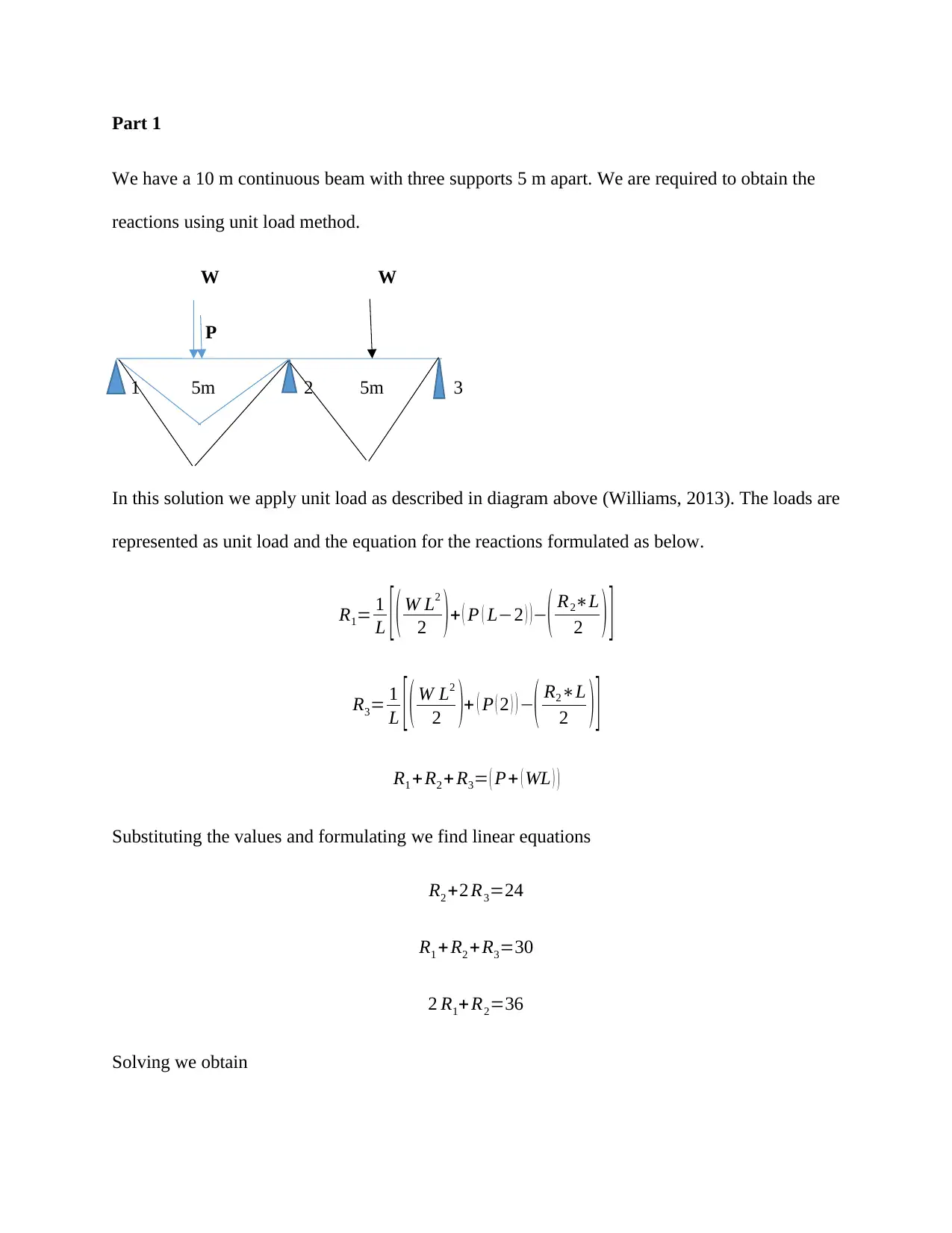
We have a 10 m continuous beam with three supports 5 m apart. We are required to obtain the
reactions using unit load method.
W W
P
1 1 5m 2 5m 3
In this solution we apply unit load as described in diagram above (Williams, 2013). The loads are
represented as unit load and the equation for the reactions formulated as below.
R1= 1
L [ ( W L2
2 )+ ( P ( L2 ) )( R2L
2 ) ]
R3= 1
L [ ( W L2
2 )+ ( P ( 2 ) ) ( R2L
2 ) ]
R1 +R2 + R3= ( P+ ( WL ) )
Substituting the values and formulating we find linear equations
R2 +2 R3=24
R1 +R2 + R3=30
2 R1+ R2=36
Solving we obtain

Secure Best Marks with AI Grader

Need help grading? Try our AI Grader for instant feedback on your assignments.
Document Page
R1=6 kN , R2=24 kN , R3 =0 kN
Part 2
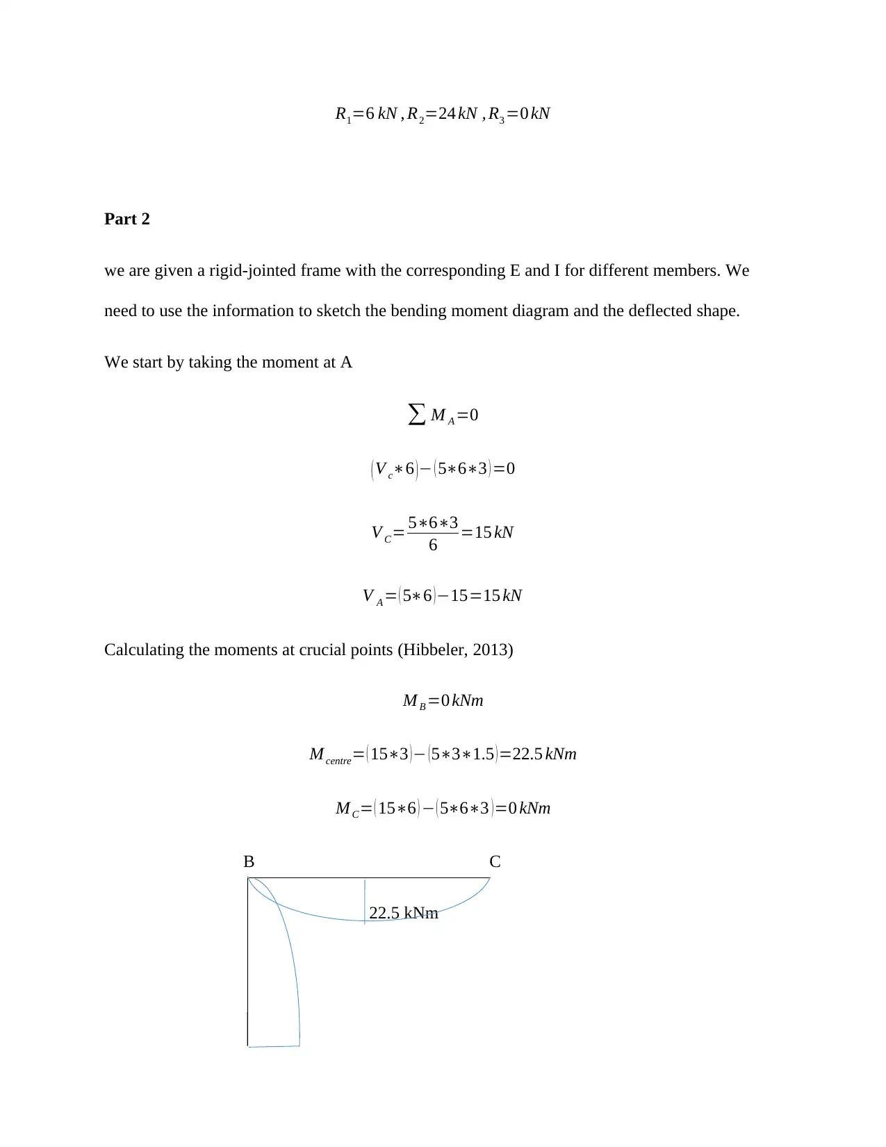
we are given a rigid-jointed frame with the corresponding E and I for different members. We
need to use the information to sketch the bending moment diagram and the deflected shape.
We start by taking the moment at A
M A =0
( V c6 ) ( 563 ) =0
V C= 563
6 =15 kN
V A = ( 56 )15=15 kN
Calculating the moments at crucial points (Hibbeler, 2013)
M B =0 kNm
M centre= ( 153 ) (531.5 )=22.5 kNm
M C= ( 156 ) ( 563 )=0 kNm
B C
22.5 kNm
Document Page
A MA
Deflection in members is found using the calculated moments and the given values of Young’s
modulus and I.
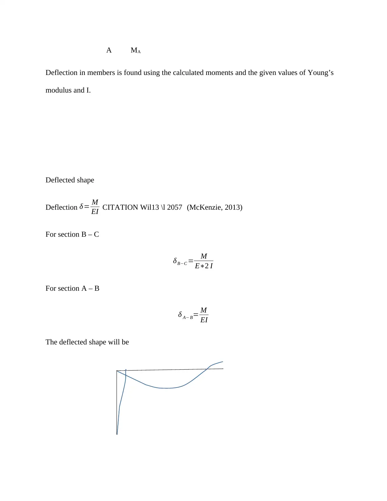
Deflected shape
Deflection δ= M
EI CITATION Wil13 \l 2057 (McKenzie, 2013)
For section B – C
δBC = M
E2 I
For section A – B
δ A B= M
EI
The deflected shape will be
Document Page
Part 3
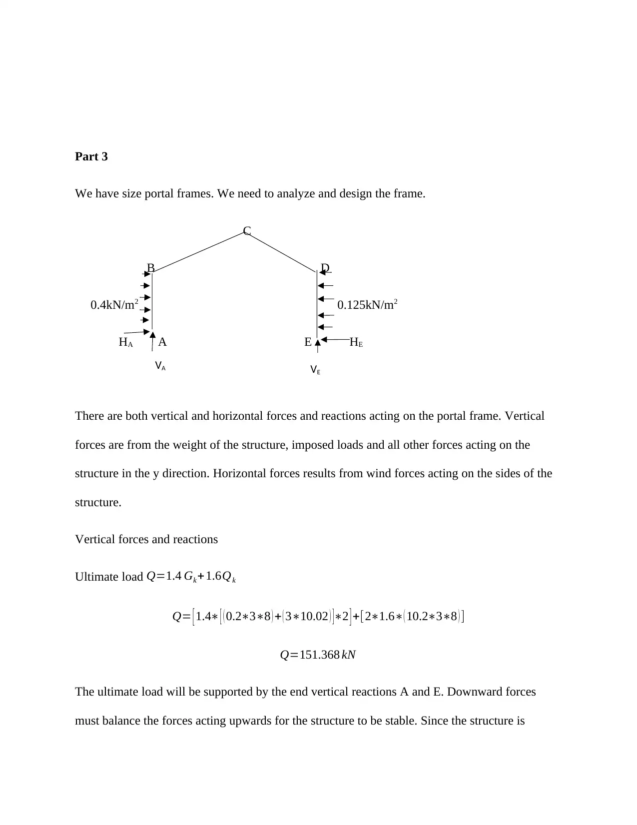
We have size portal frames. We need to analyze and design the frame.
C
B D
0.4kN/m2 0.125kN/m2
HA A E HE
There are both vertical and horizontal forces and reactions acting on the portal frame. Vertical
forces are from the weight of the structure, imposed loads and all other forces acting on the
structure in the y direction. Horizontal forces results from wind forces acting on the sides of the
structure.
Vertical forces and reactions
Ultimate load Q=1.4 Gk+1.6Qk
Q= [ 1.4 [ ( 0.238 ) + ( 310.02 ) ]2 ] +[21.6( 10.238 ) ]
Q=151.368 kN
The ultimate load will be supported by the end vertical reactions A and E. Downward forces
must balance the forces acting upwards for the structure to be stable. Since the structure is
VA VE

Secure Best Marks with AI Grader

Need help grading? Try our AI Grader for instant feedback on your assignments.
Document Page
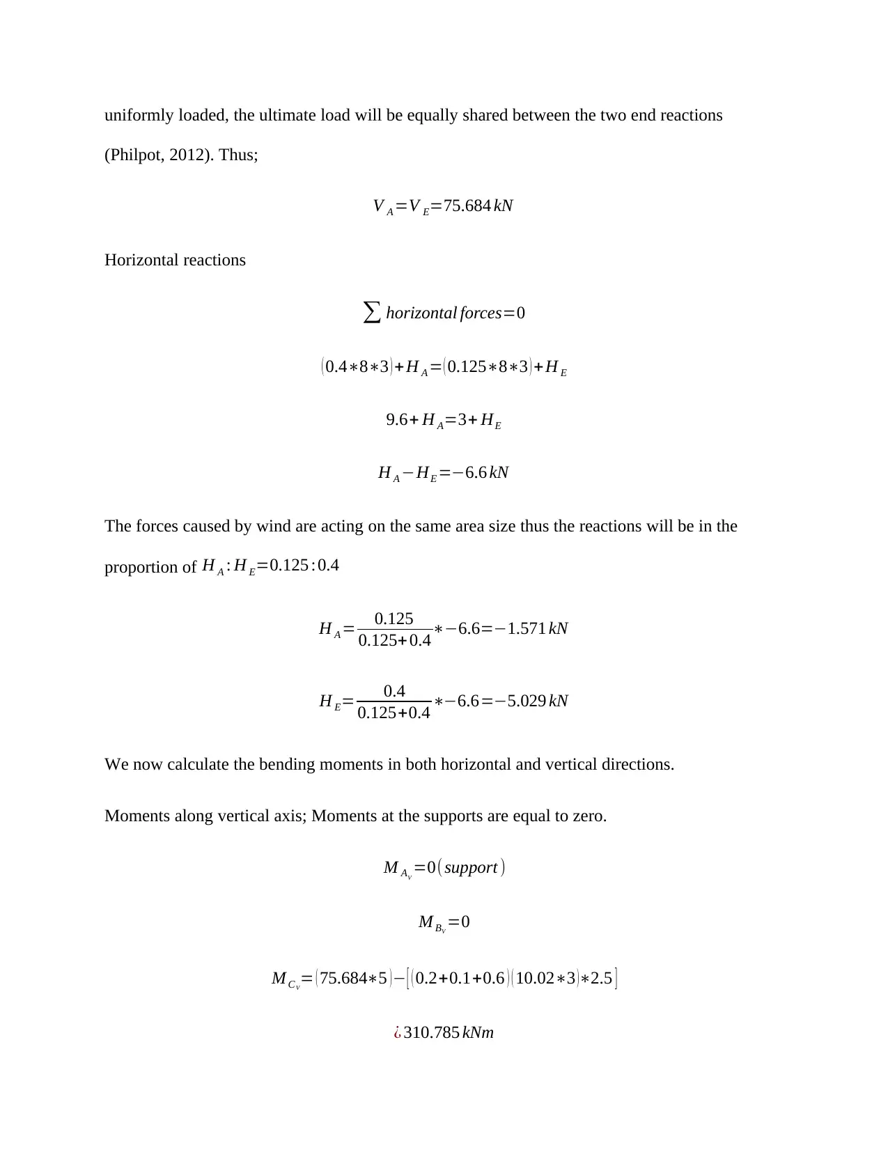
uniformly loaded, the ultimate load will be equally shared between the two end reactions
(Philpot, 2012). Thus;
V A =V E=75.684 kN
Horizontal reactions
horizontal forces=0
( 0.483 ) +H A = ( 0.12583 ) +H E
9.6+ H A=3+ HE
H A HE =6.6 kN
The forces caused by wind are acting on the same area size thus the reactions will be in the
proportion of H A : H E=0.125 :0.4
H A = 0.125
0.125+ 0.46.6=1.571 kN
H E= 0.4
0.125+0.4 6.6=5.029 kN
We now calculate the bending moments in both horizontal and vertical directions.
Moments along vertical axis; Moments at the supports are equal to zero.
M AV
=0(support )
M BV
=0
M CV
= ( 75.6845 ) [ ( 0.2+0.1+0.6 ) ( 10.023 )2.5 ]
¿ 310.785 kNm
Document Page
M D V
=0
M E V
=0
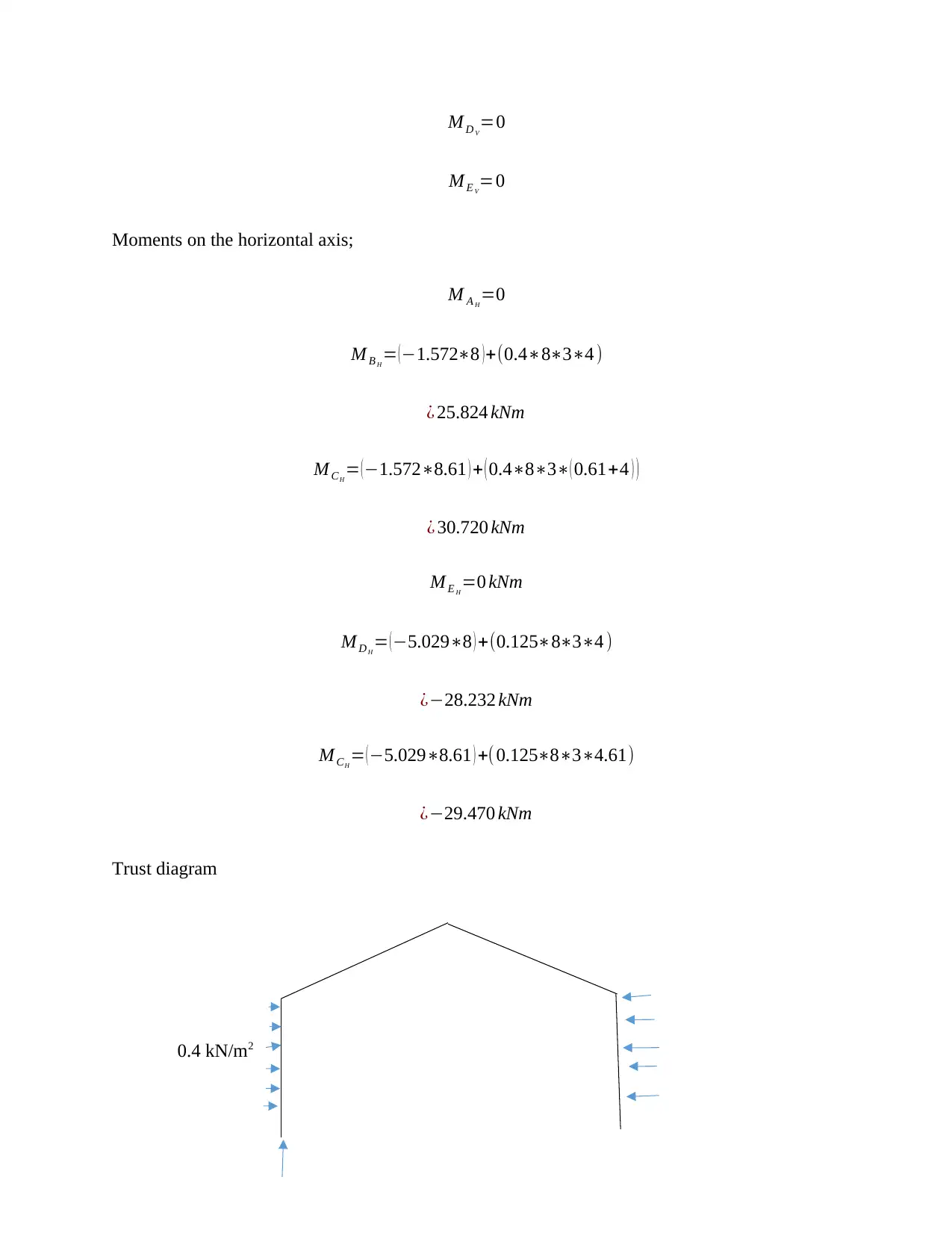
Moments on the horizontal axis;
M A H
=0
M B H
= ( 1.5728 ) +(0.4834 )
¿ 25.824 kNm
M CH
= (1.5728.61 ) + ( 0.483( 0.61+4 ) )
¿ 30.720 kNm
M E H
=0 kNm
M D H
= ( 5.0298 ) +(0.125834 )
¿28.232 kNm
M CH
= (5.0298.61 ) +(0.125834.61)
¿29.470 kNm
Trust diagram
0.4 kN/m2
Document Page
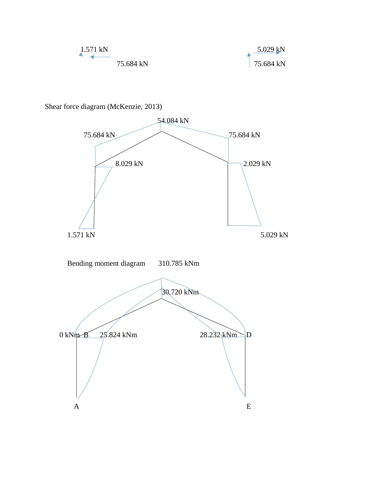
1.571 kN 5.029 kN
75.684 kN 75.684 kN
Shear force diagram (McKenzie, 2013)
54.084 kN
75.684 kN 75.684 kN
8.029 kN 2.029 kN
1.571 kN 5.029 kN
Bending moment diagram 310.785 kNm
30.720 kNm
0 kNm B 25.824 kNm 28.232 kNm D
A E

Paraphrase This Document

Need a fresh take? Get an instant paraphrase of this document with our AI Paraphraser
Document Page
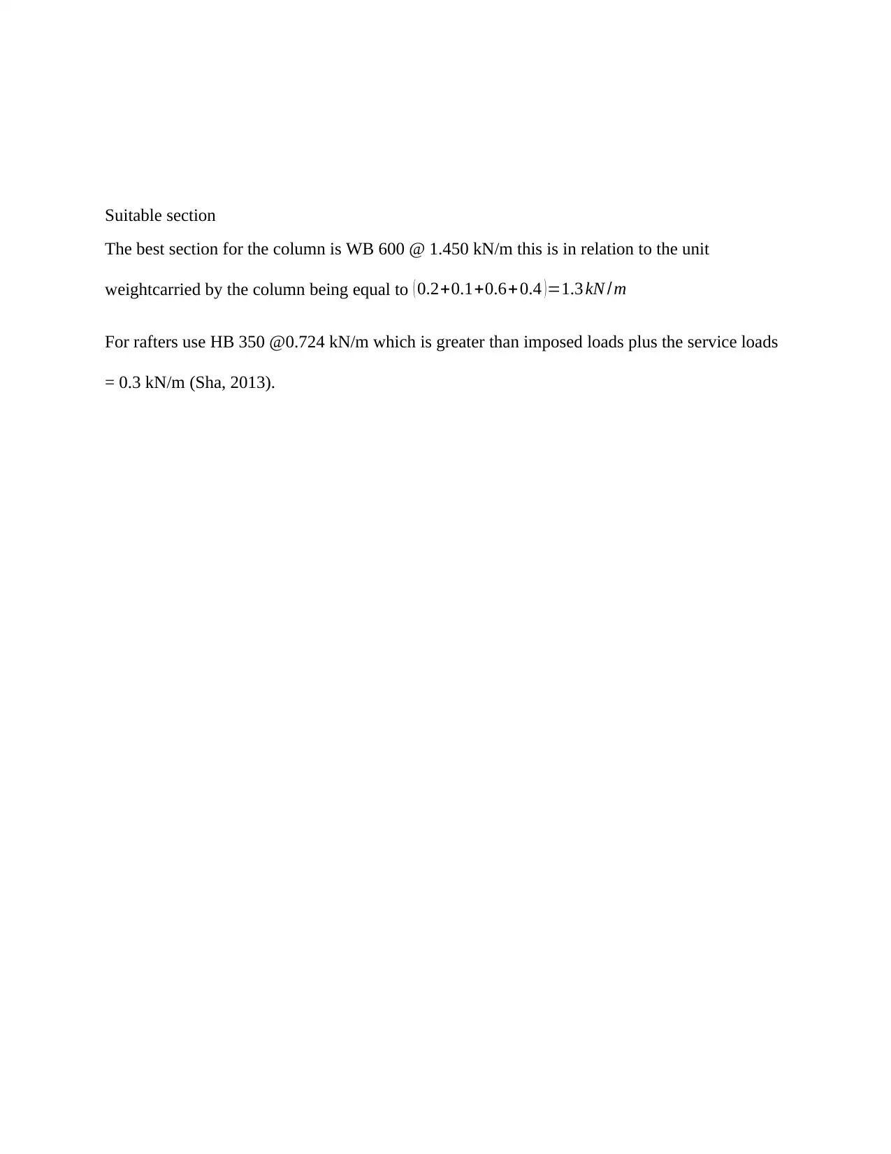
Suitable section
The best section for the column is WB 600 @ 1.450 kN/m this is in relation to the unit
weightcarried by the column being equal to ( 0.2+0.1+0.6+ 0.4 )=1.3 kN /m
For rafters use HB 350 @0.724 kN/m which is greater than imposed loads plus the service loads
= 0.3 kN/m (Sha, 2013).
Document Page
References
Hibbeler, R. C., 2013. Engineering Mechanics: Dynamics. In: Engineering mechanics. s.l.:Pearson, pp. 76-
109.
McKenzie, W., 2013. Design of Structural Elements. In: s.l.:Macmillan International Higher Education, pp.
46-65.
McKenzie, W. M., 2013. Examples in Structural Analysis, Second Edition. In: s.l.:CRC Press, pp. 453-463.
Philpot, T. A., 2012. Mechanics of Materials: An Integrated Learning System. In: s.l.:John Wiley & Sons,
pp. 234-310.
Sha, W., 2013. Steels: From Materials Science to Structural Engineering. In: s.l.:Springer Science &
Business Media, pp. 13-76.
Williams, C. D., 2013. Analysis of Statically Indeterminate Structures. In: s.l.:Literary Licensing, LLC, pp.
101-132.
1 out of 9
circle_padding
hide_on_mobile
zoom_out_icon
[object Object]

Your All-in-One AI-Powered Toolkit for Academic Success.

Available 24*7 on WhatsApp / Email

[object Object]