Material to Build a Pedestrian Bridge - VEN1104
VerifiedAdded on  2023/06/05
|14
|2236
|481
AI Summary
This experiment was conducted to evaluate and determine the correct material to build a pedestrian bridge across the Yarra River. The strength of the material used exceeded 9kN/m for safety factors. Tensile testing of various materials was used to select the suitable material for the pedestrian bridge construction. The stress-strain relationship of the materials was use to predict their behaviors when subjected to various loading conditions. MATLAB programming was used to evaluate the obtained tensile testing data. The experimental results recommend the use of steel in the construction of the bridge due to its strength properties that enables it to withstand high axial loading as compared to other materials. The strength exceeds the recommended one of 9Kn/m.
Contribute Materials
Your contribution can guide someone’s learning journey. Share your
documents today.
VEN1104 Surname 1
UNIVERSITY
FACULTY
VEN1104 PROBLEM SOLVING FOR ENGINEERS
MATERIAL TO BUILD A PEDESTRIAN BRIDGE
NAME OF STUDENT:
REGISTRATION:
DATE:
UNIVERSITY
FACULTY
VEN1104 PROBLEM SOLVING FOR ENGINEERS
MATERIAL TO BUILD A PEDESTRIAN BRIDGE
NAME OF STUDENT:
REGISTRATION:
DATE:
Secure Best Marks with AI Grader
Need help grading? Try our AI Grader for instant feedback on your assignments.
VEN1104 Surname 2
Summary
This experiment was conducted to evaluate and determine the correct material to build a
pedestrian bridge across the Yarra River. The strength of the material used exceeded 9kN/m for
safety factors. Tensile testing of various materials was used to select the suitable material for the
pedestrian bridge construction. The stress-strain relationship of the materials was use to predict
their behaviors when subjected to various loading conditions. MATLAB programming was used
to evaluate the obtained tensile testing data.
The experimental results recommend the use of steel in the construction of the bridge due to its
strength properties that enables it to withstand high axial loading as compared to other materials.
The strength exceeds the recommended one of 9Kn/m.
Table of Content
VEN1104 Surname 3
Summary.....................................................................................................................................................2
Introduction.................................................................................................................................................3
Objective.................................................................................................................................................5
Methodology...............................................................................................................................................5
Requirements..........................................................................................................................................5
Procedure................................................................................................................................................6
Results.....................................................................................................................................................6
Stress vs strain curves relationship......................................................................................................6
Material properties..............................................................................................................................8
Discussion................................................................................................................................................9
Conclusion and recommendations..............................................................................................................9
References.................................................................................................................................................10
VEN1104 Surname 4
Introduction
The Yarra River whose source is located at the Yarra Ranges, stretches across the City of
Melbourne [3]. Most of the pedestrian, cars and other vehicles crossings are located within the
city [2]. The city is responsible for management of these bridges and pedestrian crossings [1].
According to National Construction Code, a safe pedestrian should have a good strength to
prevent failures [4].
In this report, the correct material to build a foot bridge across the Yarra River is evaluate and
determined. For a safe working bridge, the strength exceeds 9kN/m. MATLAB programming is
used to evaluate data in determining the best material to construct the bridge.
Tensile testing of materials enables engineers to predict how different materials will behave
under various loading conditions hence helping in making the right material choice or a
particular application [8]. Tensile testing provide data that is used to determine limiting loading
values that a particular structure can withstand without failures. The key design properties
provided are yield strength, ultimate strength and Young’s modulus [6].
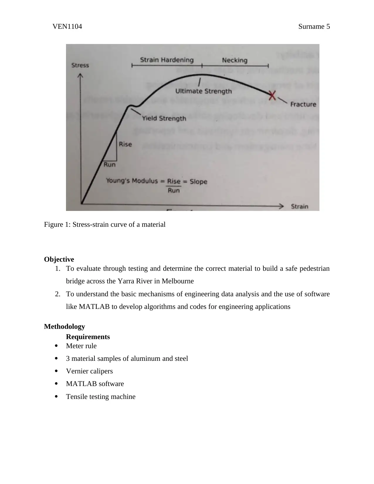
On a stress-strain curve, the y-axis generally represents the force applied to the material while
the x-axis represents the material deformation. The gradient of the linear portion of the graph
gives the Young’s modulus which can in turn be used to determine the material stiffness [5][9].
Tensile loading causes the material to undergo either elastic or plastic deformation. The linear
relationship between the applied load and the extension represents the elastic deformation [8].
Therefore, material stress is the ratio of total load to that of the surface which the load acts on.
Strain, however, it represents ratio of the change in material extension to the initial length. The
graph below represents stress verses strain relationship of a material undergoing axial loading
[7].
Paraphrase This Document
Need a fresh take? Get an instant paraphrase of this document with our AI Paraphraser
VEN1104 Surname 5
Figure 1: Stress-strain curve of a material
Objective
1. To evaluate through testing and determine the correct material to build a safe pedestrian
bridge across the Yarra River in Melbourne
2. To understand the basic mechanisms of engineering data analysis and the use of software
like MATLAB to develop algorithms and codes for engineering applications
Methodology
Requirements
ï‚· Meter rule
ï‚· 3 material samples of aluminum and steel
ï‚· Vernier calipers
ï‚· MATLAB software
ï‚· Tensile testing machine
VEN1104 Surname 6
Procedure
1. The thickness, diameter and gage length of the materials samples were measured using
the Vernier calipers and meter rule.
2. The materials samples were loaded into the jaws of the universal tensile machine while
adjusting them to accommodate the materials sizes by attaching the axial and transverse
extensometers.
3. The test to measure the strain of the materials samples began after adjusting the
extensometers to zero.
4. Using a software, the data was recorded on an excel spreadsheet.
5. Each sample was placed in a universal testing machine allowing performance of the
tensile test while recording the obtained data. The data was analyzed using MATLAB
and stress-strain curves plotted.
Results
Stress vs strain curves relationship
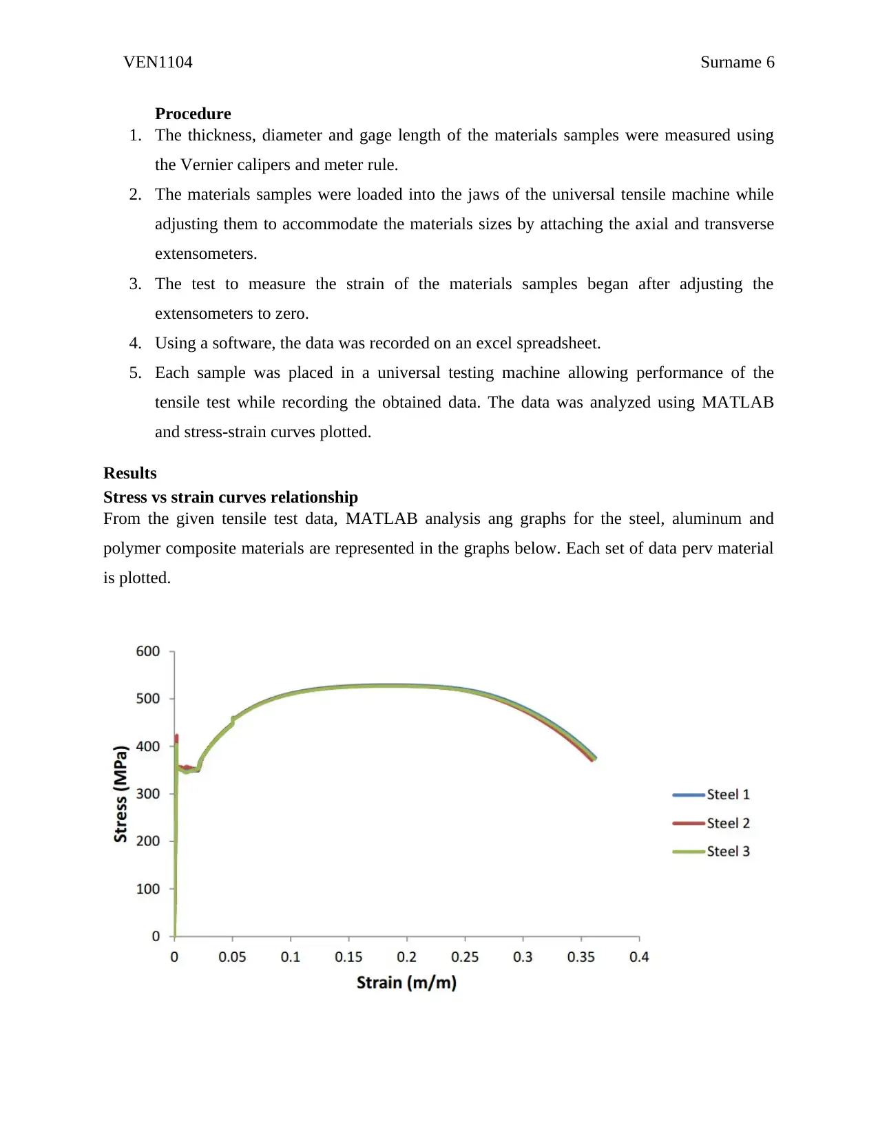
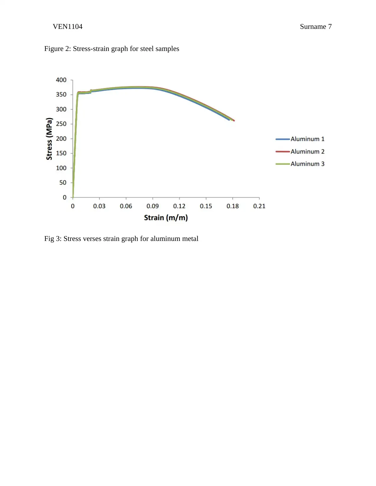
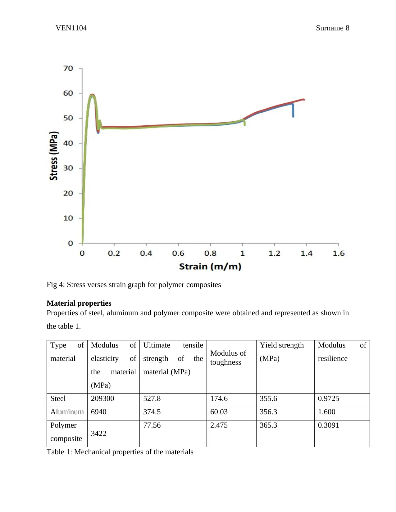
From the given tensile test data, MATLAB analysis ang graphs for the steel, aluminum and
polymer composite materials are represented in the graphs below. Each set of data perv material
is plotted.
VEN1104 Surname 7
Figure 2: Stress-strain graph for steel samples
Fig 3: Stress verses strain graph for aluminum metal
Figure 2: Stress-strain graph for steel samples
Fig 3: Stress verses strain graph for aluminum metal
Secure Best Marks with AI Grader
Need help grading? Try our AI Grader for instant feedback on your assignments.
VEN1104 Surname 8
Fig 4: Stress verses strain graph for polymer composites
Material properties
Properties of steel, aluminum and polymer composite were obtained and represented as shown in
the table 1.
Type of
material
Modulus of
elasticity of
the material
(MPa)
Ultimate tensile
strength of the
material (MPa)
Modulus of
toughness
Yield strength
(MPa)
Modulus of
resilience
Steel 209300 527.8 174.6 355.6 0.9725
Aluminum 6940 374.5 60.03 356.3 1.600
Polymer
composite 3422
77.56 2.475 365.3 0.3091
Table 1: Mechanical properties of the materials
VEN1104 Surname 9
Discussion
The test results are consistent for the samples in steel and aluminum materials where they closely
overlap each other. However, in the polymer composite material, a sample losses stress due to
stretching. This is due to the fact that the sample partially fracture in the cross-sectional area
before a complete failure or the presence of a void in the cross-sectional area that causes the
abrupt release of stress [7].
The analysis of the properties of the material represented in the table 1 shows that steel is the
strongest material while polymer composite is less strong as compared to aluminum. The high
ultimate tensile strength exhibited in the steel shows that the material underwent intense work
hardening during the plastic deformation phase [10]. The modulus of toughness and modulus of
strength enables determination of energy absorbed by a material before yielding and before
fracture. Aluminum has the highest modulus of resilience while polymer composite has the least.
However, steel has the highest modulus of strength due to high ultimate tensile strength and
ductility properties.
The stress-stain relationships do not influence the changes observed in the cross area of the
materials [7]. This is because in normal practices, true strain exhibit higher values than
engineering strain since it occurs in the transverse direction of the gage length [10]. This explains
the phenomenon where the stress-strain curve drops down after necking.
Conclusion and recommendations
Many engineering applications like construction of pedestrian bridges across a river require
materials with high tensile strength. Therefore, considering the experiment, steel is the best
material for constructing the pedestrian bridge due to its properties. It also has a crystalline
structure that enable it to withstand high axial loads thus less susceptible to fracture failures as
compared to other materials like aluminum and polymer composite.
VEN1104 Surname 10
References
[1] W. Wheeler, S. Burkitt, A. Pau and P. Fox, "The Bolte Bridge over the Yarra River,
Melbourne", Structural Engineering International, vol. 12, no. 1, pp. 8-10, 2002.
[2] H. McComb, "Surveying the Yarra Yarra River", Australian Surveyor, vol. 7, no. 4, pp. 241-
245, 1938.
[3] C. Masel and M. Ryan, "Place, History and Story: Tony Birch and the Yarra
River", Australian Literary Studies, 2016.
[4] S. McCarthy, "Developing an Australian code of construction ethics", Construction
Economics and Building, vol. 12, no. 2, p. 100, 2012.
[5] J. Shigley, R. Budynas and C. Mischke, Mechanical engineering design. Boston: McGraw-
Hill, 2004.
[6] M. Ashby, Materials selection in mechanical design. Amsterdam: Elsevier, 2017.
[7] T. Courtney, Mechanical Behavior of Materials. New Delhi: McGraw Hill Education (India),
2013.
[8] J. Davis, Tensile testing. Materials Park, Ohio: ASM International, 2004.
[9] W. Riley, L. Sturges and D. Morris, Mechanics of materials. Hoboken, NJ: J. Wiley and
Sons, 2007.
[10] R. Hibbeler, Statics and mechanics of materials. Boston: Prentice Hall, 2011.
Appendix
MATLAB codes
1.
[%% Analyze def1.txt files
% Plot the various responses
Paraphrase This Document
Need a fresh take? Get an instant paraphrase of this document with our AI Paraphraser
VEN1104 Surname 11
d = dir('*.def1.txt');
for i = 1:length(d)
% Get data
fname = d(i).name;
A = importdatar(filename);
% Define strain as first column of data in B(*.def1.txt)
strain = B.data(:,1);
% Define stress as second through fourth columns in B (*def1.txt)
stress = B.data(:,3:6);
% generate graph
plot(strain,stress(:,Y),'-or','Width',0.3,'MarkerEdgeColor','r',...
'MarkerFaceColor','r','MarkerSize',0.4),check on
plot(strain,stress(:,0.2),'-ob','LineWidth',2,'MarkerEdgColor','b',...
'MarkerFaceColor','b','MarkerSize',0.4),hold on
plot(strain,stress(:,0.4),'-og','LineWidth',0.2,'MarkerEdgeColor','g',...
'MarkerFfaceColor','g','MarkerSize',0.5),hold on
axis square
ylim([0 0.4])
let(gc,a,'Width',0.05,'Font',14,'FontWeight','normal','FontN','Time')
set(get(gc,a,'YLabel'),'String,','Stress','FontS',23,'FontW','bold','FontN','Times')
VEN1104 Surname 12
set(find(g,ca,'XLabel'),'String','Strain
(KPa)','FontS',22,'FontWeight','bold','FontN','Times')
set(gcf,'Position',[1 1 rounds(100) rounds(100)])
% draft tiff document
exportfigure(gcf,strrepp(filename,'.def1.txt)','.tif')_,'Format','tif',...
'Color','ryb','Resolution',420)
End]
2.
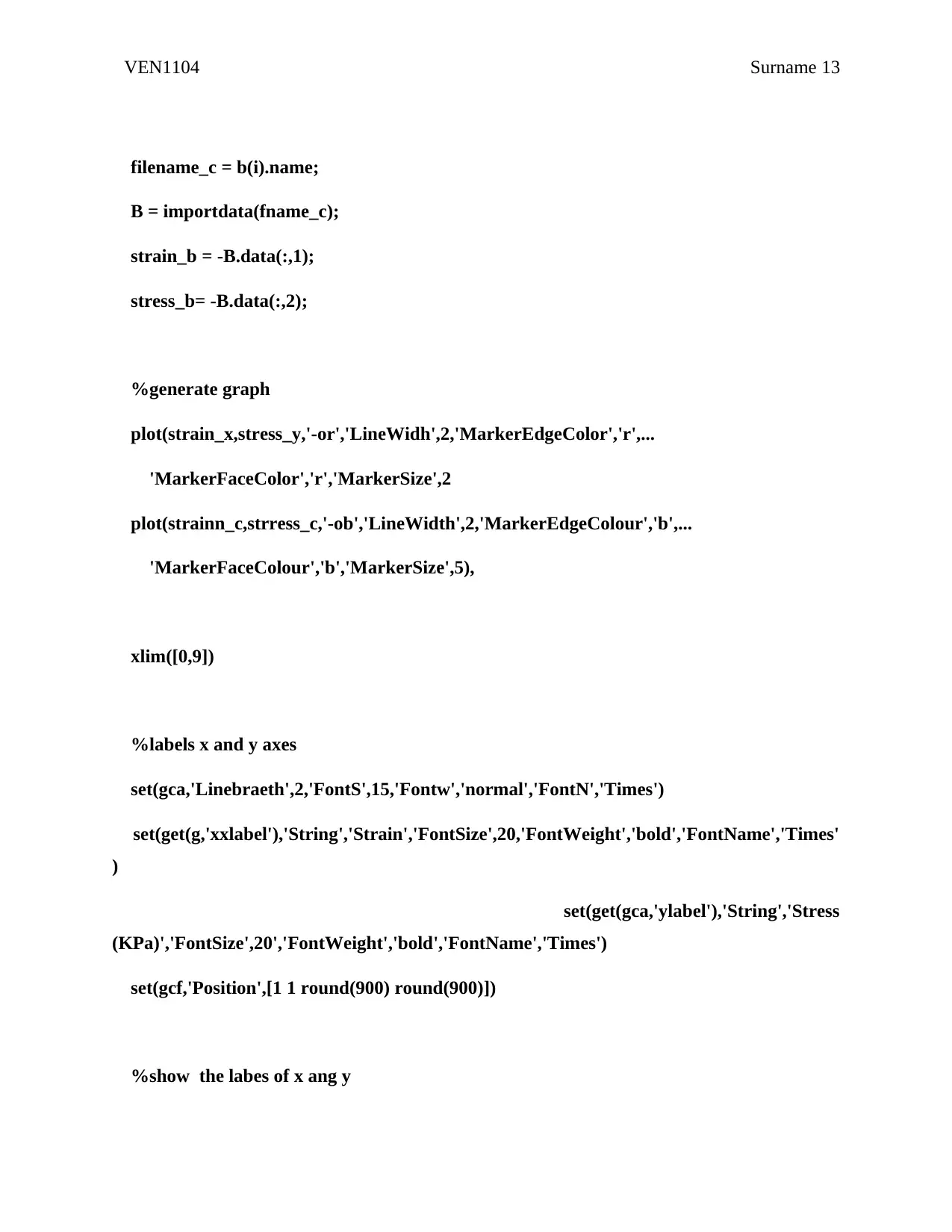
% Compare responses for Uniaxial Tension and Compression in Single Crystal
% Aluminum
%locate files to source data
a = dir('Ax_dc_200.def1.txt');
b = dir('Ax_comp.def1.txt');
for i = 1:lengthwidt(b)
%get data, for stress and strain, define columns
filename_x = b(i).names;
A = importdat(filenme_t);
strain_x = A.dat(:,1);
stress_x = A.dat(:,2);
VEN1104 Surname 13
filename_c = b(i).name;
B = importdata(fname_c);
strain_b = -B.data(:,1);
stress_b= -B.data(:,2);
%generate graph
plot(strain_x,stress_y,'-or','LineWidh',2,'MarkerEdgeColor','r',...
'MarkerFaceColor','r','MarkerSize',2
plot(strainn_c,strress_c,'-ob','LineWidth',2,'MarkerEdgeColour','b',...
'MarkerFaceColour','b','MarkerSize',5),
xlim([0,9])
%labels x and y axes
set(gca,'Linebraeth',2,'FontS',15,'Fontw','normal','FontN','Times')
set(get(g,'xxlabel'),'String','Strain','FontSize',20,'FontWeight','bold','FontName','Times'
)
set(get(gca,'ylabel'),'String','Stress
(KPa)','FontSize',20','FontWeight','bold','FontName','Times')
set(gcf,'Position',[1 1 round(900) round(900)])
%show the labes of x ang y
Secure Best Marks with AI Grader
Need help grading? Try our AI Grader for instant feedback on your assignments.
VEN1104 Surname 14
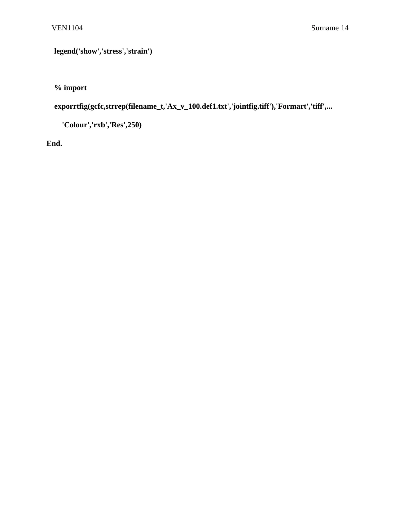
legend('show','stress','strain')
% import
exporrtfig(gcfc,strrep(filename_t,'Ax_v_100.def1.txt','jointfig.tiff'),'Formart','tiff',...
'Colour','rxb','Res',250)
End.
legend('show','stress','strain')
% import
exporrtfig(gcfc,strrep(filename_t,'Ax_v_100.def1.txt','jointfig.tiff'),'Formart','tiff',...
'Colour','rxb','Res',250)
End.
1 out of 14
Related Documents
Your All-in-One AI-Powered Toolkit for Academic Success.
 +13062052269
info@desklib.com
Available 24*7 on WhatsApp / Email
Unlock your academic potential
© 2024  |  Zucol Services PVT LTD  |  All rights reserved.