Phase Transformations: Methods for Determining Phase Diagrams and Predicting Solidification Sequences
Added on 2023-05-28
13 Pages1699 Words500 Views
Phase Transformations
First Name Last Name
Instructor
Course
8 December 2018
Research question: How long might such annealing treatments take?
A minimum duration of 4-8 hours is commonly adopted in short cycle annealing.
However, full annealing treatments has been noted to vary from metal to metal during
which the respective material austenite. A complete annealing treatment ordinarily
results in the second most flexible express a metal can expect for metal amalgam. Its
incentive is to start an unchanging and stable microstructure that nearly looks like the
metal's stage outline balance microstructure, along these lines giving the metal a
chance to accomplish moderately low dimensions of stiffness, yield class in addition
to great quality with extraordinary versatility and durability. To play out a full
toughen on a steel for instance, steel is warmed to marginally over the austenitic
temperature and held for adequate time to enable the material to completely frame
austenite or austenite-cementite grain structure. The material is then permitted to cool
gradually with the goal that the coherence microstructure is gotten. Much of the time
this implies the material is permitted to heater cool now and again its air cooled. The
cooling rate of the steel must be adequately ease back in order to not give the
austenite possibility to change into bainite or martensite, however in its place have it
totally change to pearlite and ferrite or cementite. This implies steels that are entirely
hardenable (i.e. will in general frame martensite under tolerably low cooling rates)
must be heater cooled.
Research question: Find three other methods which can be employed for determining
phase diagrams. For what are they applicable?
a. Cooling curves
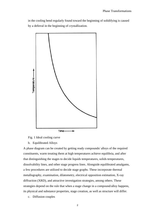
The temperature of a sample is observed while permitted to cool normally from a
raised temperature in the fluid field. The state of the subsequent curves of
temperature versus time are then investigated for deviations from the smooth bend
found for materials experiencing no stage changes (Fig. 1). Be that as it may, the
genuine solidifying/liquefying temperature is hard to decide from a cooling bend
due to the non- equilibrium conditions inborn in such a dynamic test. The plunge
1
First Name Last Name
Instructor
Course
8 December 2018
Research question: How long might such annealing treatments take?
A minimum duration of 4-8 hours is commonly adopted in short cycle annealing.
However, full annealing treatments has been noted to vary from metal to metal during
which the respective material austenite. A complete annealing treatment ordinarily
results in the second most flexible express a metal can expect for metal amalgam. Its
incentive is to start an unchanging and stable microstructure that nearly looks like the
metal's stage outline balance microstructure, along these lines giving the metal a
chance to accomplish moderately low dimensions of stiffness, yield class in addition
to great quality with extraordinary versatility and durability. To play out a full
toughen on a steel for instance, steel is warmed to marginally over the austenitic
temperature and held for adequate time to enable the material to completely frame
austenite or austenite-cementite grain structure. The material is then permitted to cool
gradually with the goal that the coherence microstructure is gotten. Much of the time
this implies the material is permitted to heater cool now and again its air cooled. The
cooling rate of the steel must be adequately ease back in order to not give the
austenite possibility to change into bainite or martensite, however in its place have it
totally change to pearlite and ferrite or cementite. This implies steels that are entirely
hardenable (i.e. will in general frame martensite under tolerably low cooling rates)
must be heater cooled.
Research question: Find three other methods which can be employed for determining
phase diagrams. For what are they applicable?
a. Cooling curves
The temperature of a sample is observed while permitted to cool normally from a
raised temperature in the fluid field. The state of the subsequent curves of
temperature versus time are then investigated for deviations from the smooth bend
found for materials experiencing no stage changes (Fig. 1). Be that as it may, the
genuine solidifying/liquefying temperature is hard to decide from a cooling bend
due to the non- equilibrium conditions inborn in such a dynamic test. The plunge
1
Phase Transformations
in the cooling bend regularly found toward the beginning of solidifying is caused
by a deferral in the beginning of crystallization.
Fig. 1 Ideal cooling curve
b. Equilibrated Alloys
A phase diagram can be created by getting ready compounds/ alloys of the required
constituents, warm treating them at high temperatures achieve equilibria, and after
that distinguishing the stages to decide liquids temperatures, solids temperatures,
dissolvability lines, and other stage progress lines. Alongside equilibrated amalgams,
a few procedures are utilized to decide stage graphs. These incorporate thermal
metallography, examination, dilatometry, electrical opposition estimation, X-ray
diffraction (XRD), and attractive investigation strategies, among others. These
strategies depend on the rule that when a stage change in a compound/alloy happens,
its physical and substance properties, stage creation, as well as structure will differ.
c. Diffusion couples
2
Phase Transformations
The utilization of diffusion couples in stage graph contemplates depends on the
presumption of neighborhood equilibria at the stage interfaces in the dispersion
zone. The last infers that an imperceptibly thick layer nearby the interface in such
a dissemination zone is successfully in thermodynamic balance with its
neighboring layer on the opposite side of the interface.
Unary Diagrams
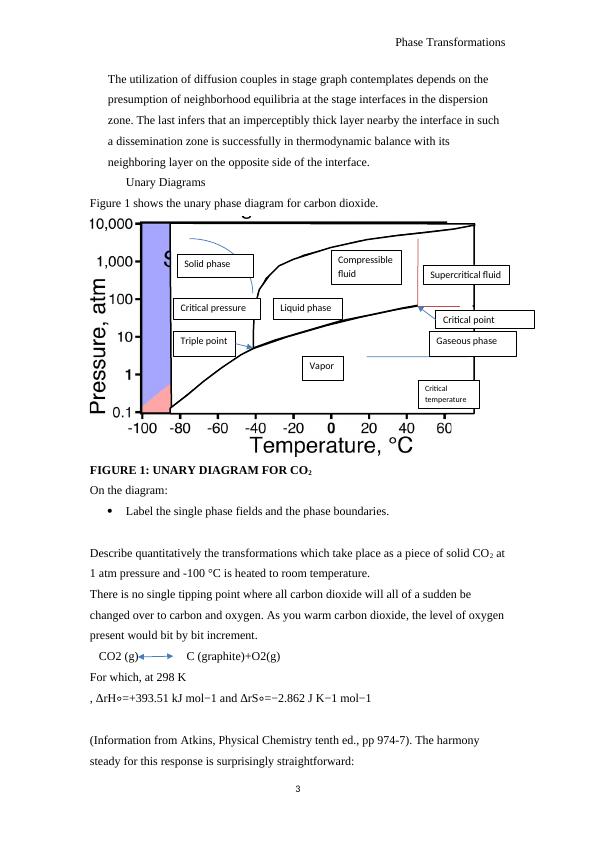
Figure 1 shows the unary phase diagram for carbon dioxide.
FIGURE 1: UNARY DIAGRAM FOR CO2
On the diagram:
Label the single phase fields and the phase boundaries.
Describe quantitatively the transformations which take place as a piece of solid CO2 at
1 atm pressure and -100 °C is heated to room temperature.
There is no single tipping point where all carbon dioxide will all of a sudden be
changed over to carbon and oxygen. As you warm carbon dioxide, the level of oxygen
present would bit by bit increment.
CO2 (g) C (graphite)+O2(g)
For which, at 298 K
, ΔrH∘=+393.51 kJ mol−1 and ΔrS∘=−2.862 J K−1 mol−1
(Information from Atkins, Physical Chemistry tenth ed., pp 974-7). The harmony
steady for this response is surprisingly straightforward:
3
Supercritical fluid
Critical
temperature
Gaseous phase
Vapor
Liquid phase
Compressible
fluid
Solid phase
Triple point
Critical pressure
Critical point
The utilization of diffusion couples in stage graph contemplates depends on the
presumption of neighborhood equilibria at the stage interfaces in the dispersion
zone. The last infers that an imperceptibly thick layer nearby the interface in such
a dissemination zone is successfully in thermodynamic balance with its
neighboring layer on the opposite side of the interface.
Unary Diagrams
Figure 1 shows the unary phase diagram for carbon dioxide.
FIGURE 1: UNARY DIAGRAM FOR CO2
On the diagram:
Label the single phase fields and the phase boundaries.
Describe quantitatively the transformations which take place as a piece of solid CO2 at
1 atm pressure and -100 °C is heated to room temperature.
There is no single tipping point where all carbon dioxide will all of a sudden be
changed over to carbon and oxygen. As you warm carbon dioxide, the level of oxygen
present would bit by bit increment.
CO2 (g) C (graphite)+O2(g)
For which, at 298 K
, ΔrH∘=+393.51 kJ mol−1 and ΔrS∘=−2.862 J K−1 mol−1
(Information from Atkins, Physical Chemistry tenth ed., pp 974-7). The harmony
steady for this response is surprisingly straightforward:
3
Supercritical fluid
Critical
temperature
Gaseous phase
Vapor
Liquid phase
Compressible
fluid
Solid phase
Triple point
Critical pressure
Critical point
Phase Transformations
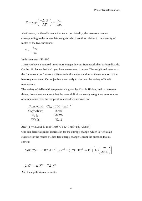
what's more, on the off chance that we expect ideality, the two exercises are
corresponding to the incomplete weights, which are thus relative to the quantity of
moles of the two substances:
In this manner if K=100
, then you have a hundred times more oxygen in your framework than carbon dioxide.
On the off chance that K=1, you have measure up to sums. The weight and volume of
the framework don't make a difference in this understanding of the estimation of the
harmony consistent. Our objective is currently to discover the variety of K with
temperature.
The variety of ΔrH∘ with temperature is given by Kirchhoff's law, and to rearrange
things, how about we accept that the warmth limits at steady weight are autonomous
of temperature over the temperature extend we are keen on:
ΔrH∘(T)=+393.51 kJ mol−1+(0.77 J K−1 mol−1)(T−298 K)
One can derive a similar expression for the entropy change, which is "left as an
exercise for the reader": Gibbs free energy change G from the question that as
shown:-
And the equilibrium constant:-
4
End of preview
Want to access all the pages? Upload your documents or become a member.
Related Documents
Different Phases in Fe-Fe3C Phase Diagramlg...
|12
|602
|224