Performance of Piles in Sand Under Different Conditions
Added on 2022-08-27
35 Pages4563 Words24 Views
Piles 1
Piles in sand
Student’s Name
Institutional Affiliation
Date
Piles in sand
Student’s Name
Institutional Affiliation
Date

Piles 2
Abstract
The main purpose of carrying out this experimental exercise was to analyze the behavior of
piles driven in sand. Specifically, the experiment involved the determination of parameters
including the pullout resistance of the piles, the head displacement (settlement), penetration
resistance and the performance of the pile under incremental load conditions. The failure load
was determined practically as well as theoretically for comparison. The results showed that
generally, the penetration depth increased with the number of blows for the 9 piles tested.
Initially, the penetration depth increases slowly with increasing blows but the rate increases
thereafter. The failure load determined experimentally was about 0.034 kN, which was higher
than that from theoretical computations(0.01778 kN ). The pullout force obtained was in the
range of 600 to 1500 g. generally, the piles requiring a greater number of driving blows into
the sand required greater force for pulling out.
Aims and objectives
This laboratory exercise was carried out with the main aim of investigating the performance
of piles in sand under different conditions. Additionally, the results from the performance of
piles in clay were processed and presented. The specific objectives for the laboratory
exercises include:
i) To investigate the head displacement of different piles in sand due to vertical
loading
ii) To determine the pile failure load
iii) To determine the force required to pull out the piles from sand after loading
iv) To determine the different properties of sand such as dry density and friction
angle. These properties are required in the subsequent sections for pile design.
Piles 3
Introduction
A pile is a long relatively thin member used in foundation construction for the
primary function of load transmission from a material of lower bearing capacity to one of
higher capacity. Other functions of a pile include soil bearing capacity improvement, the
resistance of lateral loads and the absorption of shock and wear (Viggiani, Mandolini, &
Russo, 2014). The choice of a pile for use in a particular application depends on a variety of
factors such as the stability under horizontal and vertical loading, length of the pile necessary
to develop enough frictional resistance and enough point bearing, and the long term
settlement. In addition, piles can be constructed from different types of materials including
steel, concrete, and timber (Guo, 2012).
Apparatus
The apparatus used in this laboratory exercise include,
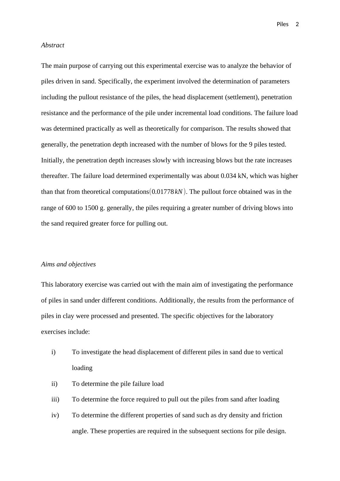
i) A large sand tank shown in figure () below. The tank consists of a steel template
supported by a frame above the surface of the sand. The steel template, in turn,
consists of 13 holes placed in a symmetric pattern which are used as channels for
driving the 9 steel piles into the sand.
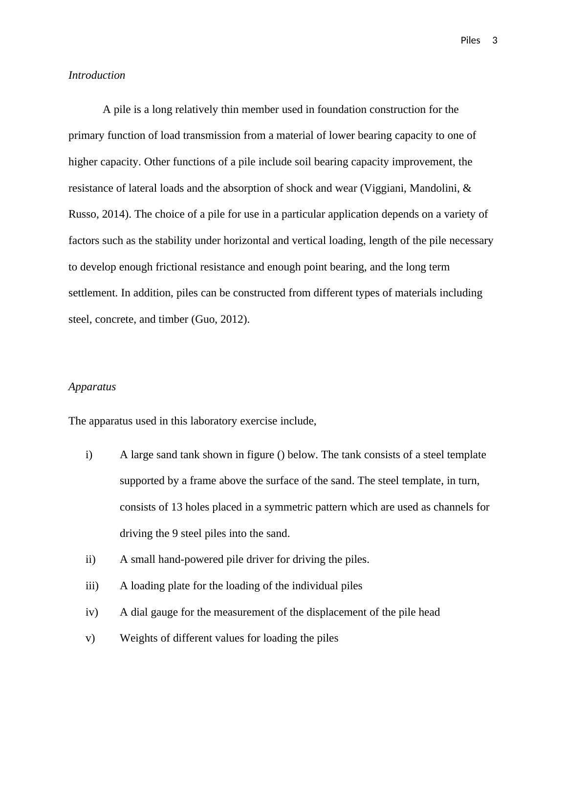
ii) A small hand-powered pile driver for driving the piles.
iii) A loading plate for the loading of the individual piles
iv) A dial gauge for the measurement of the displacement of the pile head
v) Weights of different values for loading the piles
Introduction
A pile is a long relatively thin member used in foundation construction for the
primary function of load transmission from a material of lower bearing capacity to one of
higher capacity. Other functions of a pile include soil bearing capacity improvement, the
resistance of lateral loads and the absorption of shock and wear (Viggiani, Mandolini, &
Russo, 2014). The choice of a pile for use in a particular application depends on a variety of
factors such as the stability under horizontal and vertical loading, length of the pile necessary
to develop enough frictional resistance and enough point bearing, and the long term
settlement. In addition, piles can be constructed from different types of materials including
steel, concrete, and timber (Guo, 2012).
Apparatus
The apparatus used in this laboratory exercise include,
i) A large sand tank shown in figure () below. The tank consists of a steel template
supported by a frame above the surface of the sand. The steel template, in turn,
consists of 13 holes placed in a symmetric pattern which are used as channels for
driving the 9 steel piles into the sand.
ii) A small hand-powered pile driver for driving the piles.
iii) A loading plate for the loading of the individual piles
iv) A dial gauge for the measurement of the displacement of the pile head
v) Weights of different values for loading the piles
Piles 4
Figure 1: The steel tank with the holding frame and the steel piles to the right.
Figure 2: The steel piles (left) and the loading weights (right)
Procedure
The steps outlined below constitute the procedure followed to perform the experiment
Figure 1: The steel tank with the holding frame and the steel piles to the right.
Figure 2: The steel piles (left) and the loading weights (right)
Procedure
The steps outlined below constitute the procedure followed to perform the experiment
Piles 5
i) The sand in the steel tank was loosened to a depth of 450 mm then compacted to a
uniform density
ii) The pile guide plate was then placed in the frame of the tank and the pattern and
order in which the piles were to be driven determined.
iii) Using the dynamic driving system, each of the nine piles was driven to the set
length and the blow count recorded for every 25 mm of penetration.
iv) After the blow count was recorded two piles were chosen and load tested as
follows:
The load plate was attached on each of the piles individually and the dial
gauge set up.
A load was applied in steps to the pile, up to failure conditions (the point
where the settlement was excessive compared with increasing load)
v) The pile head displacement was recorded for each load increment
vi) Using the pullout system, each of the nine piles was pulled out after the load test
completion. The maximum pullout force for each of the piles was then recorded.
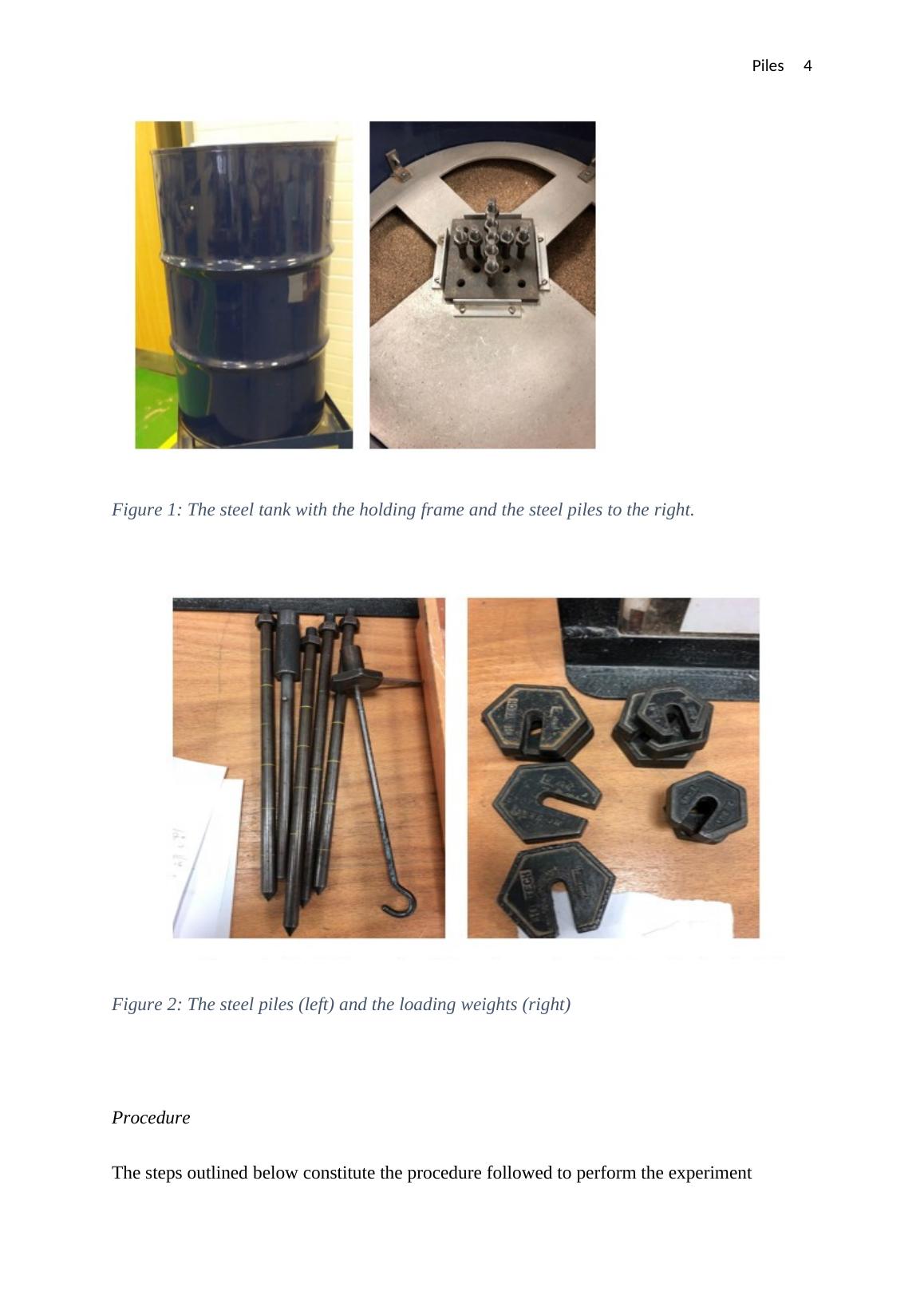
Results and Analysis
Table 1: The recorded number of blows per 50mm of penetration of the steel piles.
Depth (mm) Pile number
1 2 3 4 5 6 7 8 9
0 0 0 0 0 0 0 0 0 0
50 0 0 0 0 0 0 0 0 0
100 0 0 0 0 0 0 0 0 0
150 0 0 0 0 14 0 0 0 0
200 7 26 22 29 32 46 39 83 51
250 10 29 33 40 44 58 66 112 61
300 17 36 34 45 46 61 100 136 63
Total 34 91 89 114 136 165 205 331 175
Table 2: The head displacement of Pile 8 for different load settings.
i) The sand in the steel tank was loosened to a depth of 450 mm then compacted to a
uniform density
ii) The pile guide plate was then placed in the frame of the tank and the pattern and
order in which the piles were to be driven determined.
iii) Using the dynamic driving system, each of the nine piles was driven to the set
length and the blow count recorded for every 25 mm of penetration.
iv) After the blow count was recorded two piles were chosen and load tested as
follows:
The load plate was attached on each of the piles individually and the dial
gauge set up.
A load was applied in steps to the pile, up to failure conditions (the point
where the settlement was excessive compared with increasing load)
v) The pile head displacement was recorded for each load increment
vi) Using the pullout system, each of the nine piles was pulled out after the load test
completion. The maximum pullout force for each of the piles was then recorded.
Results and Analysis
Table 1: The recorded number of blows per 50mm of penetration of the steel piles.
Depth (mm) Pile number
1 2 3 4 5 6 7 8 9
0 0 0 0 0 0 0 0 0 0
50 0 0 0 0 0 0 0 0 0
100 0 0 0 0 0 0 0 0 0
150 0 0 0 0 14 0 0 0 0
200 7 26 22 29 32 46 39 83 51
250 10 29 33 40 44 58 66 112 61
300 17 36 34 45 46 61 100 136 63
Total 34 91 89 114 136 165 205 331 175
Table 2: The head displacement of Pile 8 for different load settings.
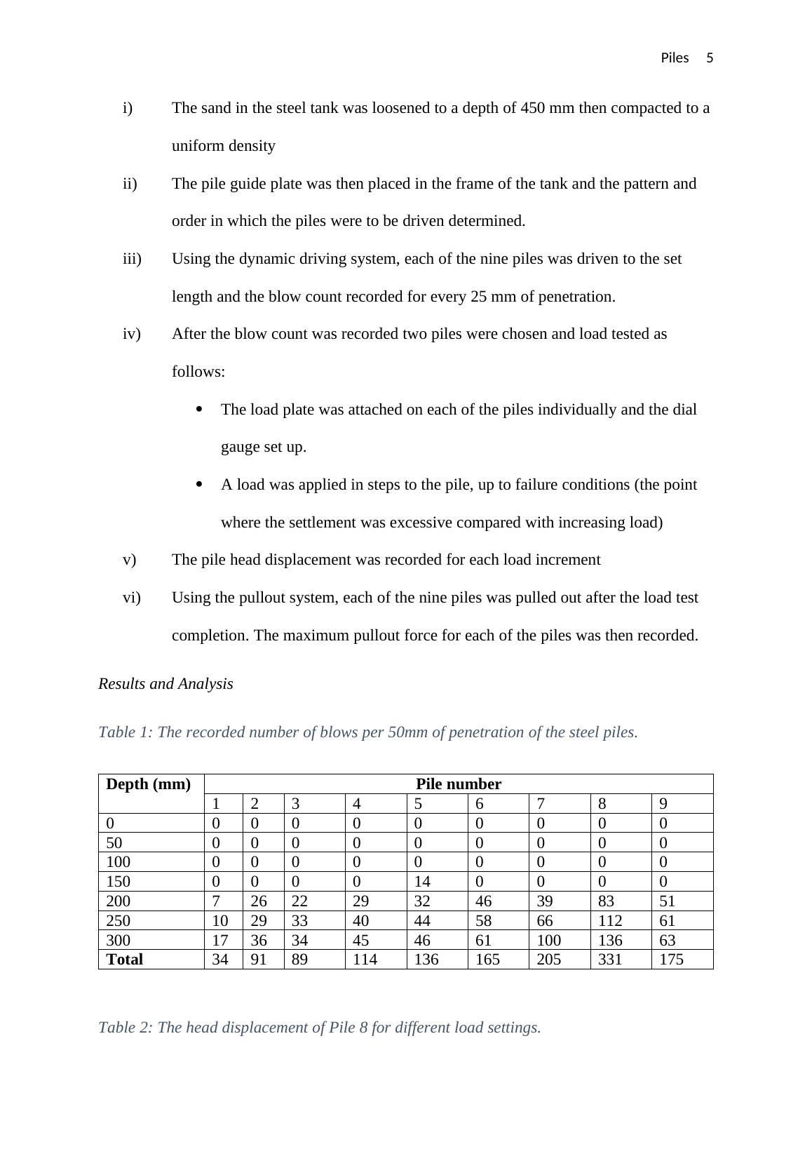
Piles 6
Pile 8
Load (g) Settlement (mm)
0 1
250 0.01
1500 0
1750 0.005
2000 0.04
2250 0.085
2500 0.145
2750 0.25
3000 0.328
3250 0.485
3500 0.79
3750 1.25
4000 1.58
4250 3.30
4500 4.04
4750 4.59
5000 10.61
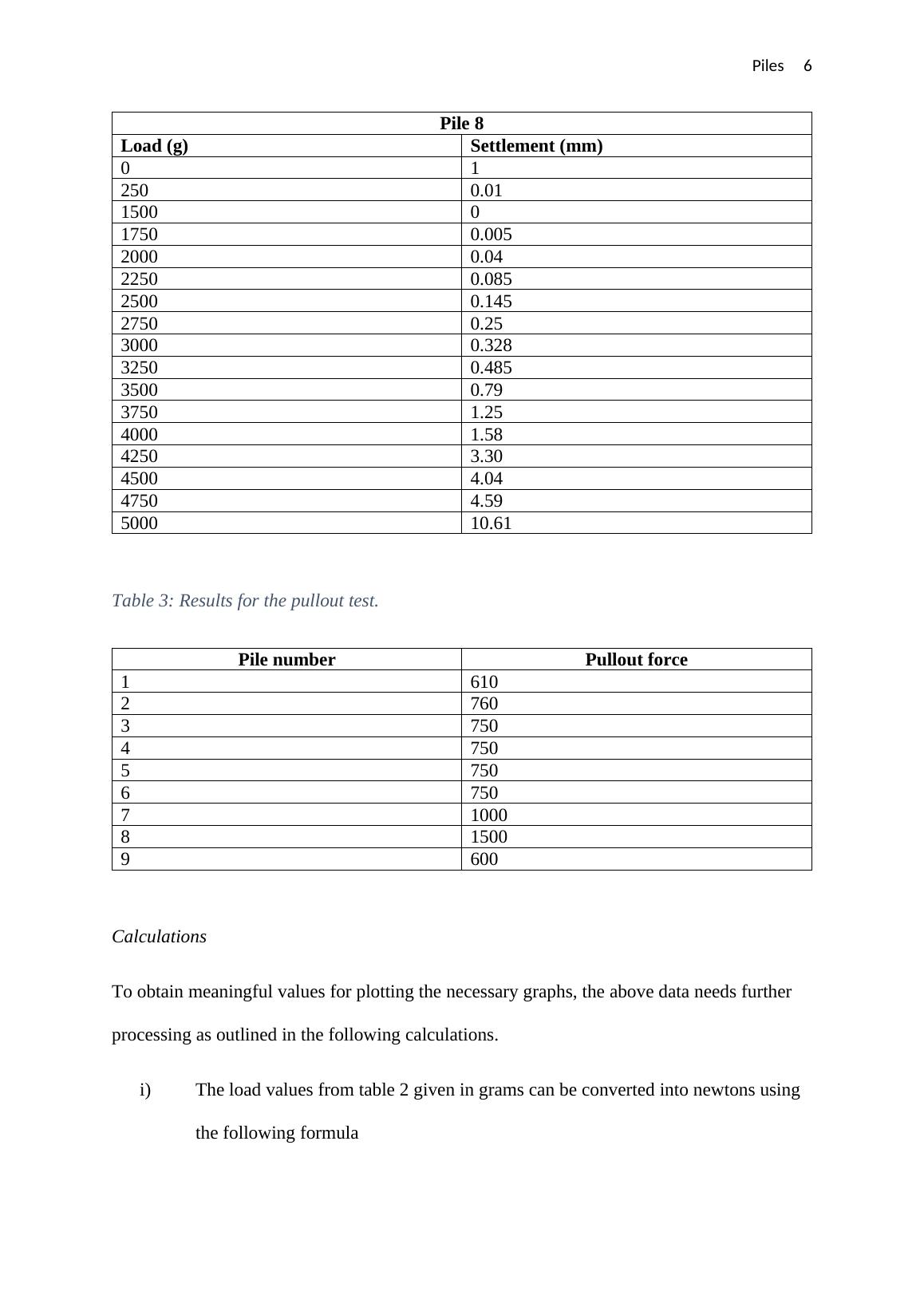
Table 3: Results for the pullout test.
Pile number Pullout force
1 610
2 760
3 750
4 750
5 750
6 750
7 1000
8 1500
9 600
Calculations
To obtain meaningful values for plotting the necessary graphs, the above data needs further
processing as outlined in the following calculations.
i) The load values from table 2 given in grams can be converted into newtons using
the following formula
Pile 8
Load (g) Settlement (mm)
0 1
250 0.01
1500 0
1750 0.005
2000 0.04
2250 0.085
2500 0.145
2750 0.25
3000 0.328
3250 0.485
3500 0.79
3750 1.25
4000 1.58
4250 3.30
4500 4.04
4750 4.59
5000 10.61
Table 3: Results for the pullout test.
Pile number Pullout force
1 610
2 760
3 750
4 750
5 750
6 750
7 1000
8 1500
9 600
Calculations
To obtain meaningful values for plotting the necessary graphs, the above data needs further
processing as outlined in the following calculations.
i) The load values from table 2 given in grams can be converted into newtons using
the following formula
Piles 7
w=mg
Where g=9.81 N /kg and m is the mass in kg. For example, considering the load of 2000 g,
the weight in N is given by,
w=
9.81 N
kg × 2000
1000 =19.62 N
Similarly, the weights of the rest of the loads were calculated and the results summarized in
table 4 below.
The effective settlement head is obtained using the following formula,
Effective settlement=settlement on load application-previous gauge reading
For instance, the effective settlement considering the 2000 g load is,
¿ 0.04−0.005=0.035 mm
A similar procedure was applied to calculate the rest of the effective settlements. The results
are presented in Table 4 below.
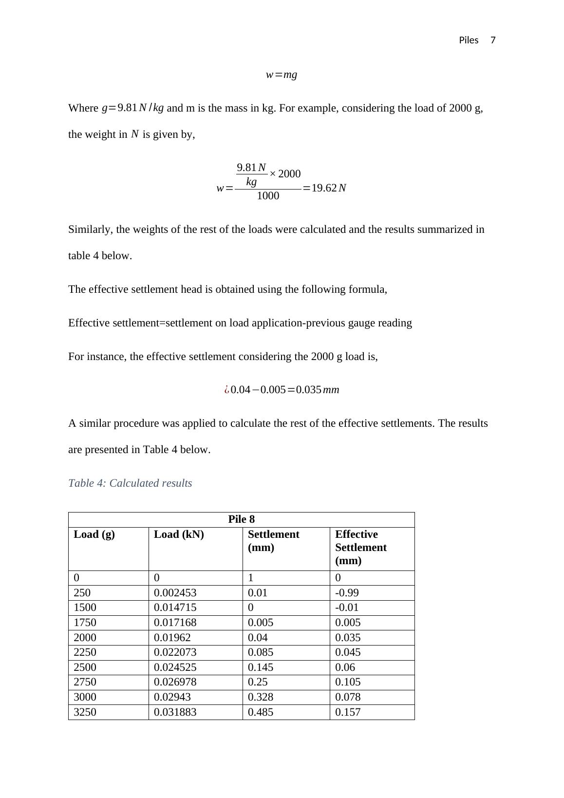
Table 4: Calculated results
Pile 8
Load (g) Load (kN) Settlement
(mm)
Effective
Settlement
(mm)
0 0 1 0
250 0.002453 0.01 -0.99
1500 0.014715 0 -0.01
1750 0.017168 0.005 0.005
2000 0.01962 0.04 0.035
2250 0.022073 0.085 0.045
2500 0.024525 0.145 0.06
2750 0.026978 0.25 0.105
3000 0.02943 0.328 0.078
3250 0.031883 0.485 0.157
w=mg
Where g=9.81 N /kg and m is the mass in kg. For example, considering the load of 2000 g,
the weight in N is given by,
w=
9.81 N
kg × 2000
1000 =19.62 N
Similarly, the weights of the rest of the loads were calculated and the results summarized in
table 4 below.
The effective settlement head is obtained using the following formula,
Effective settlement=settlement on load application-previous gauge reading
For instance, the effective settlement considering the 2000 g load is,
¿ 0.04−0.005=0.035 mm
A similar procedure was applied to calculate the rest of the effective settlements. The results
are presented in Table 4 below.
Table 4: Calculated results
Pile 8
Load (g) Load (kN) Settlement
(mm)
Effective
Settlement
(mm)
0 0 1 0
250 0.002453 0.01 -0.99
1500 0.014715 0 -0.01
1750 0.017168 0.005 0.005
2000 0.01962 0.04 0.035
2250 0.022073 0.085 0.045
2500 0.024525 0.145 0.06
2750 0.026978 0.25 0.105
3000 0.02943 0.328 0.078
3250 0.031883 0.485 0.157
Piles 8
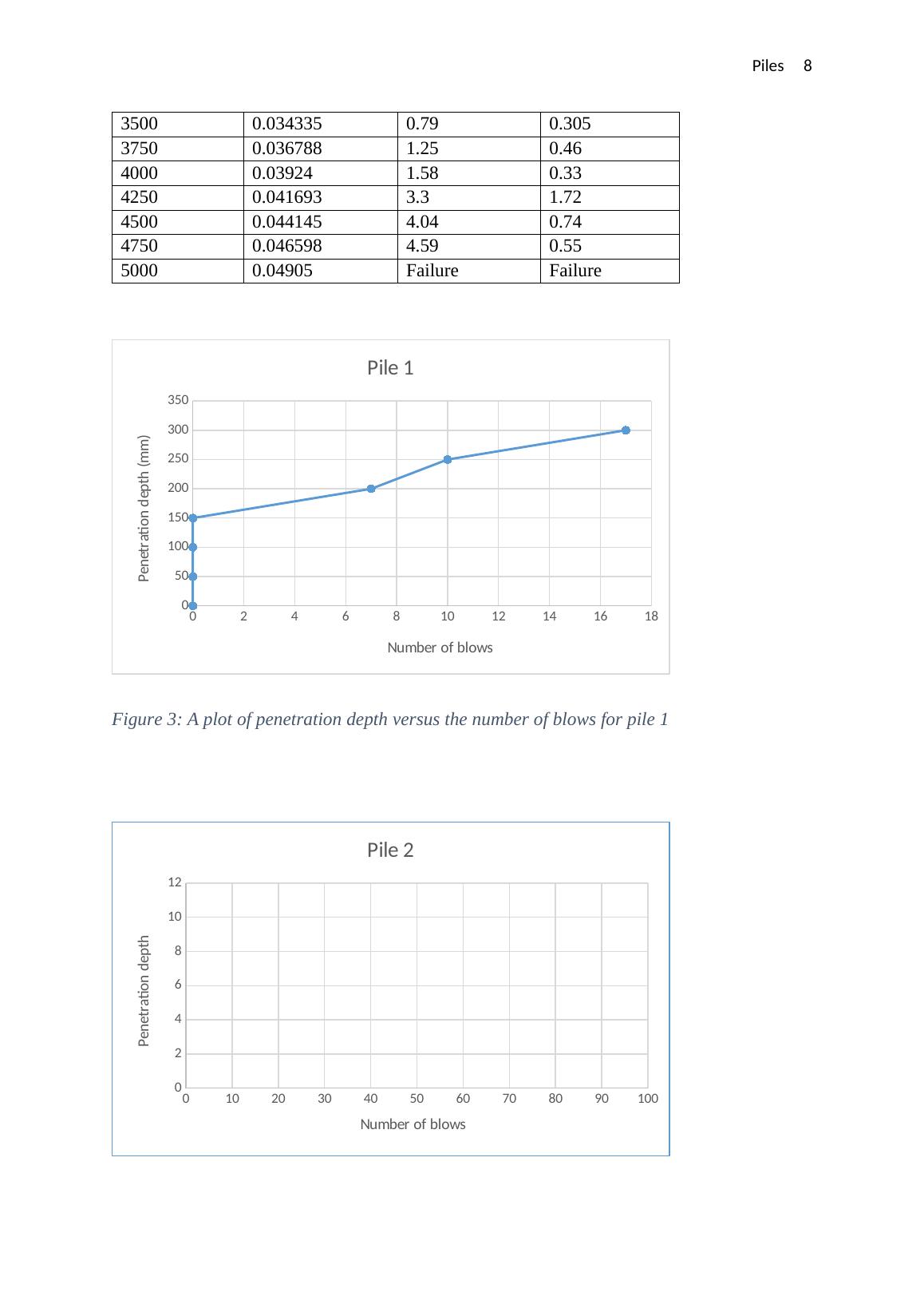
3500 0.034335 0.79 0.305
3750 0.036788 1.25 0.46
4000 0.03924 1.58 0.33
4250 0.041693 3.3 1.72
4500 0.044145 4.04 0.74
4750 0.046598 4.59 0.55
5000 0.04905 Failure Failure
0 2 4 6 8 10 12 14 16 18
0
50
100
150
200
250
300
350
Pile 1
Number of blows
Penetration depth (mm)
Figure 3: A plot of penetration depth versus the number of blows for pile 1
0 10 20 30 40 50 60 70 80 90 100
0
2
4
6
8
10
12
Pile 2
Number of blows
Penetration depth
End of preview
Want to access all the pages? Upload your documents or become a member.