Advanced Structural Analysis and Design: Plastic Analysis & WPG Design
VerifiedAdded on 2023/06/08
|13
|2140
|274
Project
AI Summary
This document presents a comprehensive solution to a Civil Engineering project, focusing on two primary areas: plastic analysis of statically indeterminate frames and the design of a welded plate girder (WPG). Part A of the project involves analyzing collapse mechanisms in frames, determining the critical collapse mechanism, and calculating the associated plastic moment. The solution demonstrates the application of plastic analysis methods. Part B addresses the open-ended design and detailed steelwork design of a WPG. This includes calculating loads, bending moments, and shear forces, followed by the selection of appropriate girder dimensions, flange areas, and web thicknesses. The design process incorporates considerations for bending and shear stresses, and the provision of stiffeners. The document also provides a discussion on design considerations including plate girder construction, stresses and loads application, permissible stresses, and bending and shear stresses. The solution references relevant codes of practice and industry standards, providing a practical application of structural engineering principles.
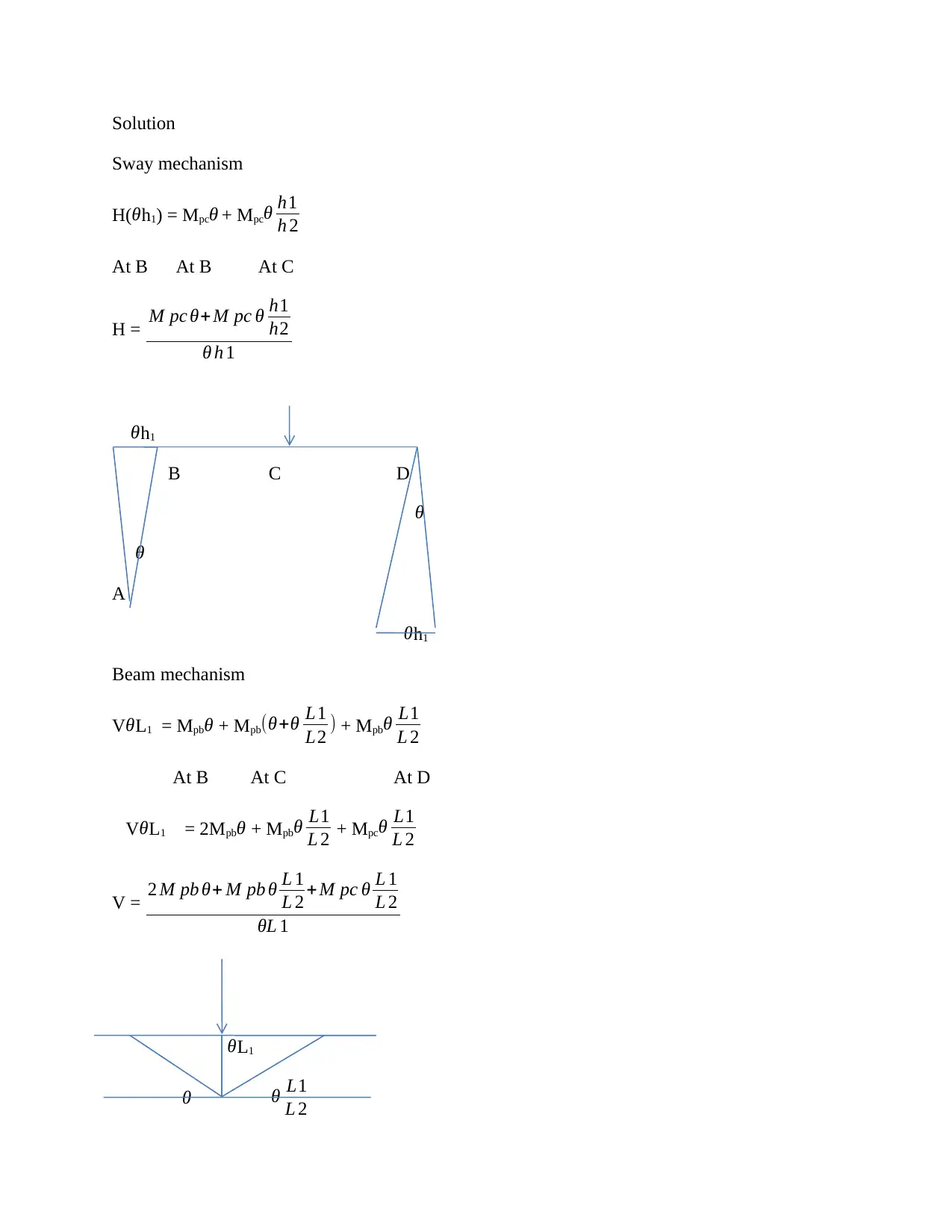
Solution
Sway mechanism
H(θh1) = Mpcθ + Mpcθ h1
h 2
At B At B At C
H = M pc θ+ M pc θ h1
h2
θ h 1
θh1
B C D
θ
θ
A
θh1
Beam mechanism
VθL1 = Mpbθ + Mpb(θ+θ L1
L2 ) + Mpbθ L1
L 2
At B At C At D
VθL1 = 2Mpbθ + Mpbθ L1
L 2 + Mpcθ L1
L 2
V = 2 M pb θ+ M pb θ L 1
L 2 +M pc θ L 1
L 2
θL 1
θL1
θ θ L1
L 2
Sway mechanism
H(θh1) = Mpcθ + Mpcθ h1
h 2
At B At B At C
H = M pc θ+ M pc θ h1
h2
θ h 1
θh1
B C D
θ
θ
A
θh1
Beam mechanism
VθL1 = Mpbθ + Mpb(θ+θ L1
L2 ) + Mpbθ L1
L 2
At B At C At D
VθL1 = 2Mpbθ + Mpbθ L1
L 2 + Mpcθ L1
L 2
V = 2 M pb θ+ M pb θ L 1
L 2 +M pc θ L 1
L 2
θL 1
θL1
θ θ L1
L 2
Paraphrase This Document
Need a fresh take? Get an instant paraphrase of this document with our AI Paraphraser
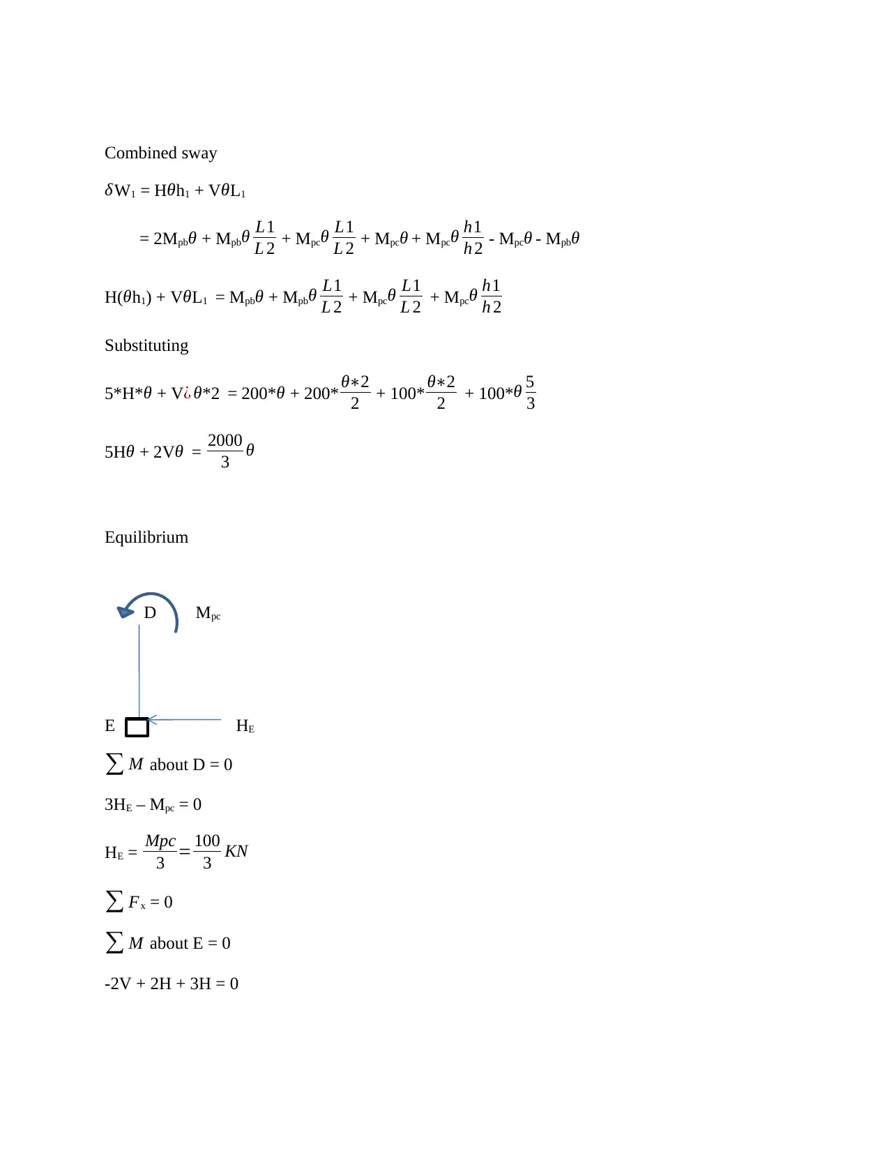
Combined sway
δW1 = Hθh1 + VθL1
= 2Mpbθ + Mpbθ L1
L 2 + Mpcθ L1
L 2 + Mpcθ + Mpcθ h1
h 2 - Mpcθ - Mpbθ
H(θh1) + VθL1 = Mpbθ + Mpbθ L1
L 2 + Mpcθ L1
L 2 + Mpcθ h1
h 2
Substituting
5*H*θ + V¿ θ*2 = 200*θ + 200* θ∗2
2 + 100* θ∗2
2 + 100*θ 5
3
5H θ + 2Vθ = 2000
3 θ
Equilibrium
D Mpc
E HE
∑ M about D = 0
3HE – Mpc = 0
HE = Mpc
3 = 100
3 KN
∑ Fx = 0
∑ M about E = 0
-2V + 2H + 3H = 0
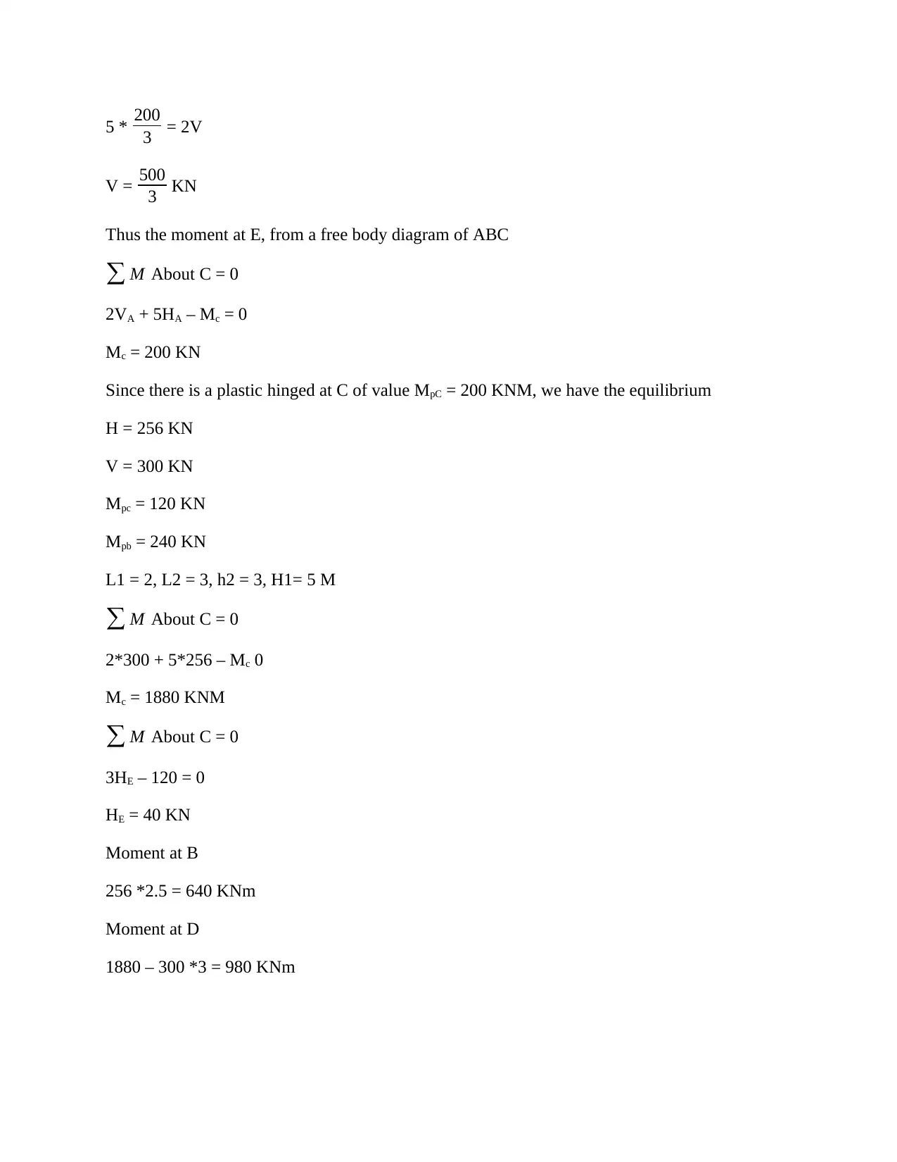
5 * 200
3 = 2V
V = 500
3 KN
Thus the moment at E, from a free body diagram of ABC
∑ M About C = 0
2VA + 5HA – Mc = 0
Mc = 200 KN
Since there is a plastic hinged at C of value MpC = 200 KNM, we have the equilibrium
H = 256 KN
V = 300 KN
Mpc = 120 KN
Mpb = 240 KN
L1 = 2, L2 = 3, h2 = 3, H1= 5 M
∑ M About C = 0
2*300 + 5*256 – Mc 0
Mc = 1880 KNM
∑ M About C = 0
3HE – 120 = 0
HE = 40 KN
Moment at B
256 *2.5 = 640 KNm
Moment at D
1880 – 300 *3 = 980 KNm
⊘ This is a preview!⊘
Do you want full access?
Subscribe today to unlock all pages.

Trusted by 1+ million students worldwide
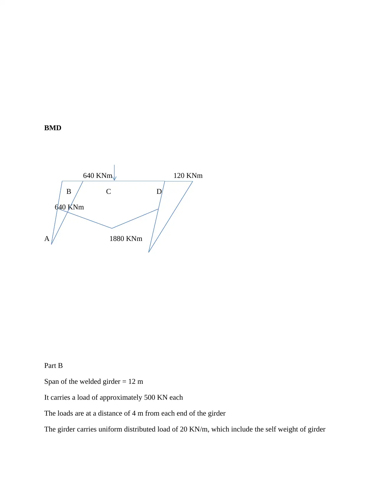
BMD
640 KNm 120 KNm
B C D
640 KNm
A 1880 KNm
Part B
Span of the welded girder = 12 m
It carries a load of approximately 500 KN each
The loads are at a distance of 4 m from each end of the girder
The girder carries uniform distributed load of 20 KN/m, which include the self weight of girder
640 KNm 120 KNm
B C D
640 KNm
A 1880 KNm
Part B
Span of the welded girder = 12 m
It carries a load of approximately 500 KN each
The loads are at a distance of 4 m from each end of the girder
The girder carries uniform distributed load of 20 KN/m, which include the self weight of girder
Paraphrase This Document
Need a fresh take? Get an instant paraphrase of this document with our AI Paraphraser
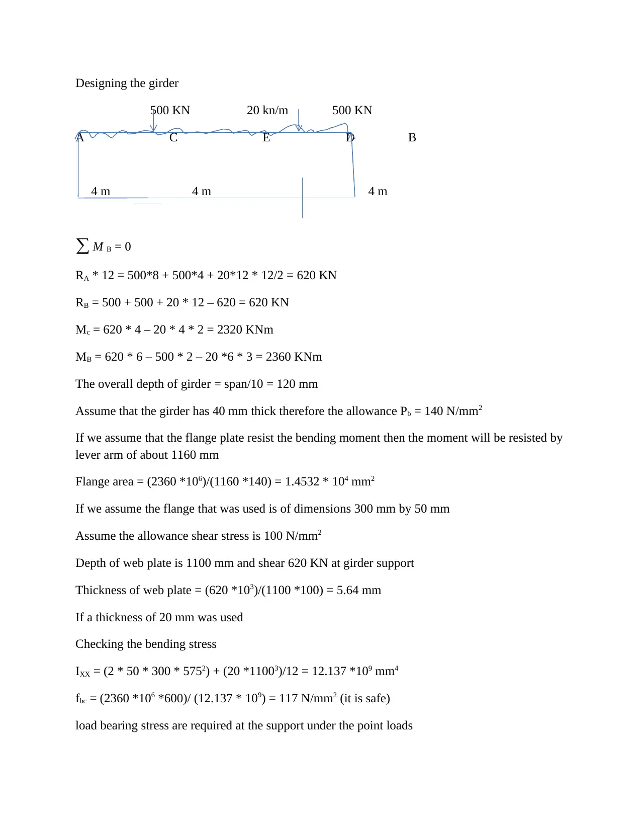
Designing the girder
500 KN 20 kn/m 500 KN
A C E D B
4 m 4 m 4 m
∑ M B = 0
RA * 12 = 500*8 + 500*4 + 20*12 * 12/2 = 620 KN
RB = 500 + 500 + 20 * 12 – 620 = 620 KN
Mc = 620 * 4 – 20 * 4 * 2 = 2320 KNm
MB = 620 * 6 – 500 * 2 – 20 *6 * 3 = 2360 KNm
The overall depth of girder = span/10 = 120 mm
Assume that the girder has 40 mm thick therefore the allowance Pb = 140 N/mm2
If we assume that the flange plate resist the bending moment then the moment will be resisted by
lever arm of about 1160 mm
Flange area = (2360 *106)/(1160 *140) = 1.4532 * 104 mm2
If we assume the flange that was used is of dimensions 300 mm by 50 mm
Assume the allowance shear stress is 100 N/mm2
Depth of web plate is 1100 mm and shear 620 KN at girder support
Thickness of web plate = (620 *103)/(1100 *100) = 5.64 mm
If a thickness of 20 mm was used
Checking the bending stress
IXX = (2 * 50 * 300 * 5752) + (20 *11003)/12 = 12.137 *109 mm4
fbc = (2360 *106 *600)/ (12.137 * 109) = 117 N/mm2 (it is safe)
load bearing stress are required at the support under the point loads
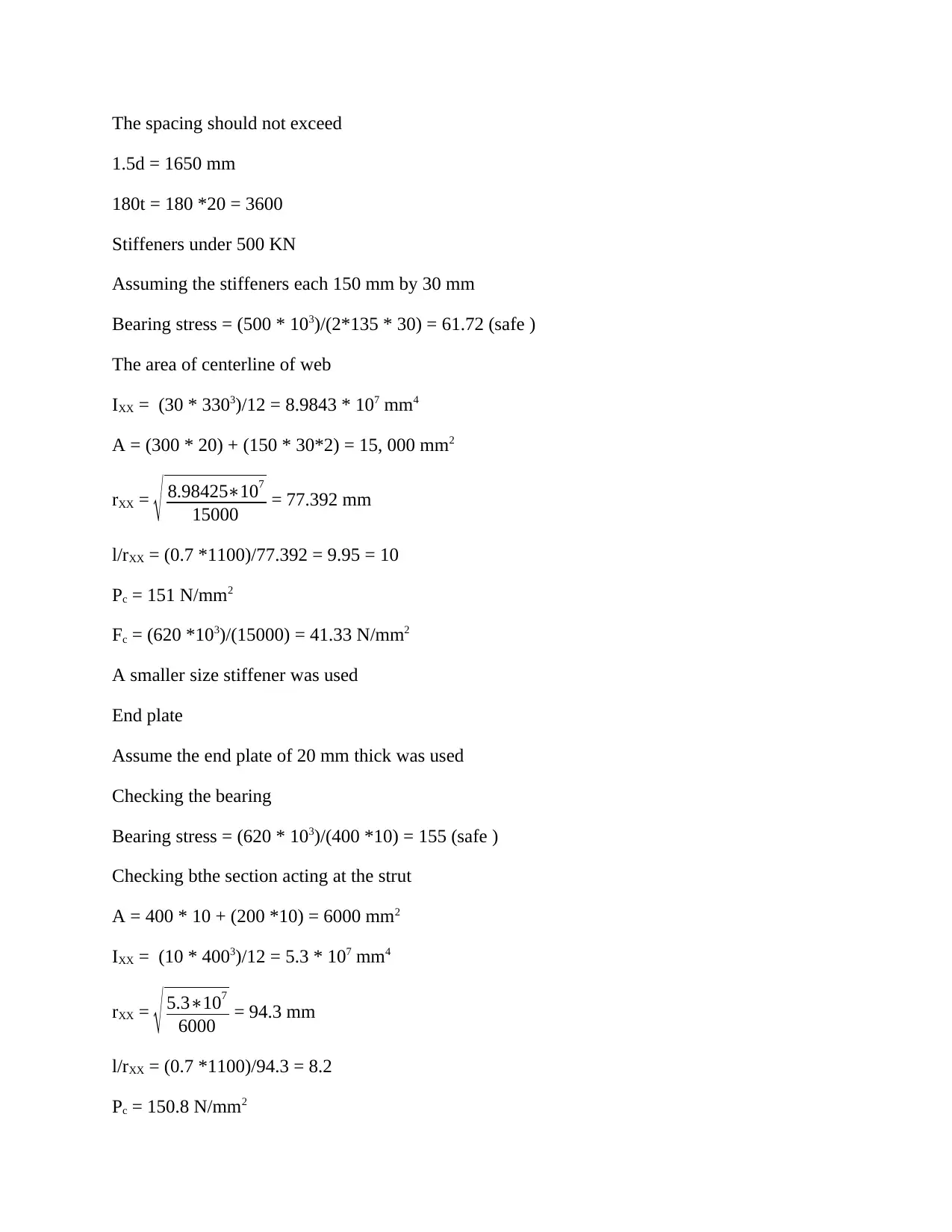
The spacing should not exceed
1.5d = 1650 mm
180t = 180 *20 = 3600
Stiffeners under 500 KN
Assuming the stiffeners each 150 mm by 30 mm
Bearing stress = (500 * 103)/(2*135 * 30) = 61.72 (safe )
The area of centerline of web
IXX = (30 * 3303)/12 = 8.9843 * 107 mm4
A = (300 * 20) + (150 * 30*2) = 15, 000 mm2
rXX = √ 8.98425∗107
15000 = 77.392 mm
l/rXX = (0.7 *1100)/77.392 = 9.95 = 10
Pc = 151 N/mm2
Fc = (620 *103)/(15000) = 41.33 N/mm2
A smaller size stiffener was used
End plate
Assume the end plate of 20 mm thick was used
Checking the bearing
Bearing stress = (620 * 103)/(400 *10) = 155 (safe )
Checking bthe section acting at the strut
A = 400 * 10 + (200 *10) = 6000 mm2
IXX = (10 * 4003)/12 = 5.3 * 107 mm4
rXX = √ 5.3∗107
6000 = 94.3 mm
l/rXX = (0.7 *1100)/94.3 = 8.2
Pc = 150.8 N/mm2
⊘ This is a preview!⊘
Do you want full access?
Subscribe today to unlock all pages.

Trusted by 1+ million students worldwide
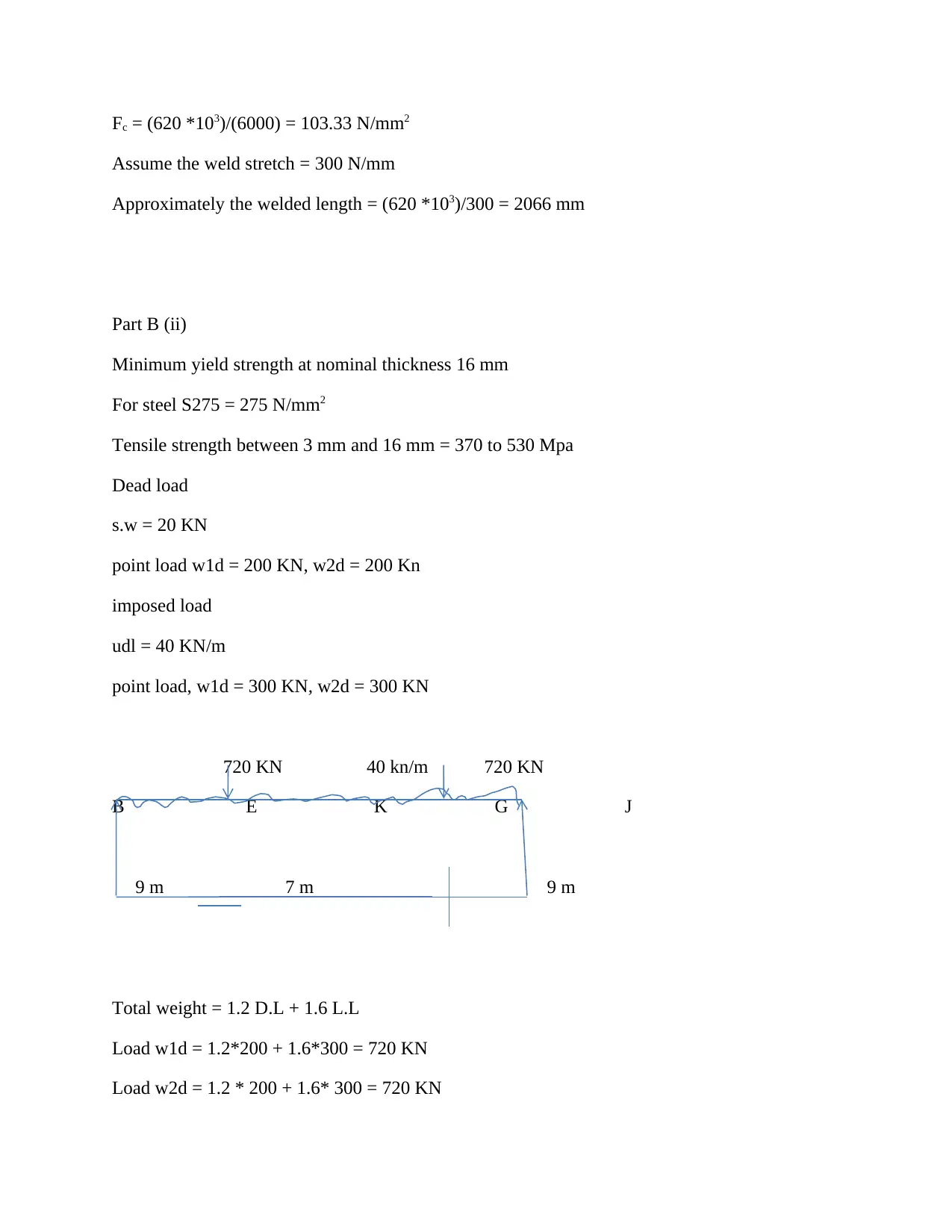
Fc = (620 *103)/(6000) = 103.33 N/mm2
Assume the weld stretch = 300 N/mm
Approximately the welded length = (620 *103)/300 = 2066 mm
Part B (ii)
Minimum yield strength at nominal thickness 16 mm
For steel S275 = 275 N/mm2
Tensile strength between 3 mm and 16 mm = 370 to 530 Mpa
Dead load
s.w = 20 KN
point load w1d = 200 KN, w2d = 200 Kn
imposed load
udl = 40 KN/m
point load, w1d = 300 KN, w2d = 300 KN
720 KN 40 kn/m 720 KN
B E K G J
9 m 7 m 9 m
Total weight = 1.2 D.L + 1.6 L.L
Load w1d = 1.2*200 + 1.6*300 = 720 KN
Load w2d = 1.2 * 200 + 1.6* 300 = 720 KN
Paraphrase This Document
Need a fresh take? Get an instant paraphrase of this document with our AI Paraphraser
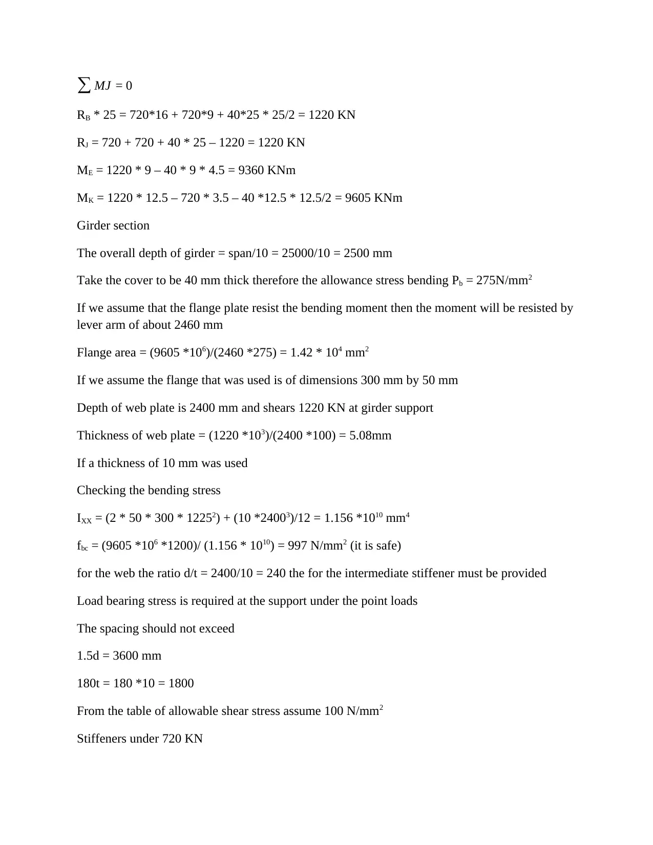
∑ MJ = 0
RB * 25 = 720*16 + 720*9 + 40*25 * 25/2 = 1220 KN
RJ = 720 + 720 + 40 * 25 – 1220 = 1220 KN
ME = 1220 * 9 – 40 * 9 * 4.5 = 9360 KNm
MK = 1220 * 12.5 – 720 * 3.5 – 40 *12.5 * 12.5/2 = 9605 KNm
Girder section
The overall depth of girder = span/10 = 25000/10 = 2500 mm
Take the cover to be 40 mm thick therefore the allowance stress bending Pb = 275N/mm2
If we assume that the flange plate resist the bending moment then the moment will be resisted by
lever arm of about 2460 mm
Flange area = (9605 *106)/(2460 *275) = 1.42 * 104 mm2
If we assume the flange that was used is of dimensions 300 mm by 50 mm
Depth of web plate is 2400 mm and shears 1220 KN at girder support
Thickness of web plate = (1220 *103)/(2400 *100) = 5.08mm
If a thickness of 10 mm was used
Checking the bending stress
IXX = (2 * 50 * 300 * 12252) + (10 *24003)/12 = 1.156 *1010 mm4
fbc = (9605 *106 *1200)/ (1.156 * 1010) = 997 N/mm2 (it is safe)
for the web the ratio d/t = 2400/10 = 240 the for the intermediate stiffener must be provided
Load bearing stress is required at the support under the point loads
The spacing should not exceed
1.5d = 3600 mm
180t = 180 *10 = 1800
From the table of allowable shear stress assume 100 N/mm2
Stiffeners under 720 KN
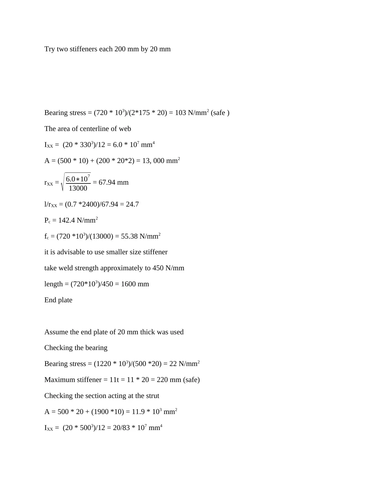
Try two stiffeners each 200 mm by 20 mm
Bearing stress = (720 * 103)/(2*175 * 20) = 103 N/mm2 (safe )
The area of centerline of web
IXX = (20 * 3303)/12 = 6.0 * 107 mm4
A = (500 * 10) + (200 * 20*2) = 13, 000 mm2
rXX = √ 6.0∗107
13000 = 67.94 mm
l/rXX = (0.7 *2400)/67.94 = 24.7
Pc = 142.4 N/mm2
fc = (720 *103)/(13000) = 55.38 N/mm2
it is advisable to use smaller size stiffener
take weld strength approximately to 450 N/mm
length = (720*103)/450 = 1600 mm
End plate
Assume the end plate of 20 mm thick was used
Checking the bearing
Bearing stress = (1220 * 103)/(500 *20) = 22 N/mm2
Maximum stiffener = 11t = 11 * 20 = 220 mm (safe)
Checking the section acting at the strut
A = 500 * 20 + (1900 *10) = 11.9 * 103 mm2
IXX = (20 * 5003)/12 = 20/83 * 107 mm4
⊘ This is a preview!⊘
Do you want full access?
Subscribe today to unlock all pages.

Trusted by 1+ million students worldwide
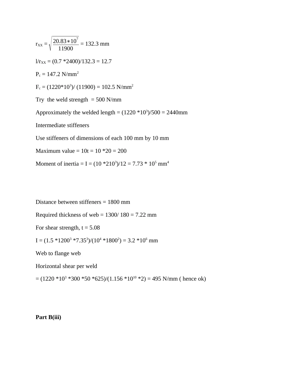
rXX = √ 20.83∗107
11900 = 132.3 mm
l/rXX = (0.7 *2400)/132.3 = 12.7
Pc = 147.2 N/mm2
Fc = (1220*103)/ (11900) = 102.5 N/mm2
Try the weld strength = 500 N/mm
Approximately the welded length = (1220 *103)/500 = 2440mm
Intermediate stiffeners
Use stiffeners of dimensions of each 100 mm by 10 mm
Maximum value = 10t = 10 *20 = 200
Moment of inertia = I = (10 *2103)/12 = 7.73 * 105 mm4
Distance between stiffeners = 1800 mm
Required thickness of web = 1300/ 180 = 7.22 mm
For shear strength, t = 5.08
I = (1.5 *12003 *7.353)/(104 *18002) = 3.2 *106 mm
Web to flange web
Horizontal shear per weld
= (1220 *103 *300 *50 *625)/(1.156 *1010 *2) = 495 N/mm ( hence ok)
Part B(iii)
Paraphrase This Document
Need a fresh take? Get an instant paraphrase of this document with our AI Paraphraser
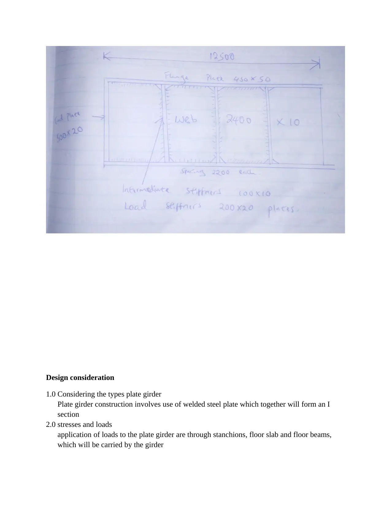
Design consideration
1.0 Considering the types plate girder
Plate girder construction involves use of welded steel plate which together will form an I
section
2.0 stresses and loads
application of loads to the plate girder are through stanchions, floor slab and floor beams,
which will be carried by the girder
1.0 Considering the types plate girder
Plate girder construction involves use of welded steel plate which together will form an I
section
2.0 stresses and loads
application of loads to the plate girder are through stanchions, floor slab and floor beams,
which will be carried by the girder
the flange of the plate will carry the bending moments while the web will have a resistance to
the shear force.
To avoid plate from failing and working effectively the rules from BS449 will be used to
govern the with or thickness ratios of the plates to ensure no buckling takes place, the rules
also will govern the positions of both the intermediate and stiffeners.
3.0 plate girder depth
the depth should always be about 1/10 of the span for average loading.
The lightly loaded girders the depth will be between 1/15 to 1/20
The flange depth is always about 1/3 of the depth
Web buckling are prevented by provision of stiffeners
4.0 plate girders deflections
Clause 15 of BS449 will be used determining the deflection requirement
5.0 permissible stresses
If the plate thickness will exceed 40 mm a lower stress must be used
The permissible bending stress to be used are provided in BS 449
6.0 bending stresses
Clause 17, 27 and 32 of BS 449 sets section area for the girders
Properties for plate girders that includes moment of inertia, area, modulus of section and radii
of gyration are calculated from the first principle.
Maximum outstand for flange plate are always provided in BS 449, like for example
Compression flange = 16t
Tension flange = 20t
t is the thickness
7.0 shear stress of the web
will be determined by the formula
fq = shear
depthof web plate∗thickness of the web
Allowable shear stress will depenf on the value of d/t and stiffeners spacing
If the ratio of d/t exceed 85 vertical stiffeners will be required at a distance which will not
exceed 1.5d
The thickness should be more than 1/180
⊘ This is a preview!⊘
Do you want full access?
Subscribe today to unlock all pages.

Trusted by 1+ million students worldwide
1 out of 13
Your All-in-One AI-Powered Toolkit for Academic Success.
+13062052269
info@desklib.com
Available 24*7 on WhatsApp / Email
![[object Object]](/_next/static/media/star-bottom.7253800d.svg)
Unlock your academic potential
Copyright © 2020–2026 A2Z Services. All Rights Reserved. Developed and managed by ZUCOL.


