Structural Design of RC Slab

Verified

Added on  2020/12/29

|70
|10525
|538
Project
AI Summary
This project focuses on the structural design and analysis of a reinforced concrete slab with a central opening. It utilizes various methods like Wood-Armer, yield line analysis, and the strip method to determine the best reinforcement layouts. The project compares different design approaches, analyzes bending moments, and assesses the slab's ultimate load capacity.

Contribute Materials

Your contribution can guide someone’s learning journey. Share your documents today.
Document Page
Politecnico Di Milano
Advanced Structural Design
Prof. Fabio Biondini
Structural Design of RC Slab
Authors:
Gupta Shashank
Patil Swaraj
Enrolment Number:
918858
915621
November 16, 2018

Secure Best Marks with AI Grader

Need help grading? Try our AI Grader for instant feedback on your assignments.
Document Page
Structural Design of RC Slab
Contents
1 Overview of Slab 2
2 Comparison of Slab and Beam model 6
3 Steel Reinforcement Design by Wood-Armer
Method 12
4 Principal Bending Moments 33
5 Yield Line Analysis 42
6 Strip Method Design of Slab reinforcement 54
1
Document Page
Structural Design of RC Slab
1 Overview of Slab
The objective of this assignment is to design and analyse the reinforcement of con-
crete slab with an central opening.
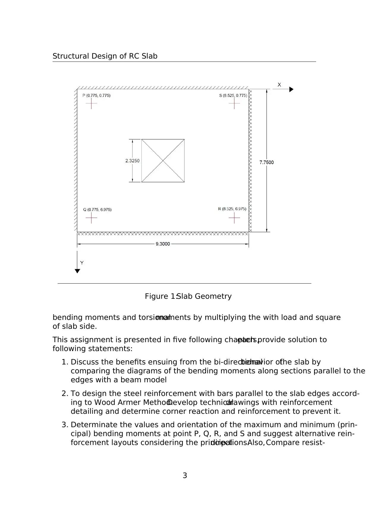
The reinforced slab is clamped on two adjacent edges and simply supported on the
others, as shown in Figure 1.The slab is to be designed at the ultimate limit state
under uniformly distributed loading.In this study, the concrete class used is C25/30
and the reinforcing steel type is B450C.
The geometrical parameters and design load are given as follows:
Slab Side, a = 6 + 1.75 = 7.75 m
Slab Depth, h ≥ a/30 ⇒ h ≥ 258.3 mm.Hence, h = 260 mm
Self Weight, gok = γ ∗ h = 6.5kN/m2
Weight of non-structural Components, g1k = 1kN/m2
Permanent Load, gk = gok + g1k = 7.5kN/m2
Live load, qk = 4kN/m2 [Recommended for D1 category of use, Table 6.2, EC1]
Safety Factors, γg = 1.35 and γk = 1.5
Design Load, pu = γg gk + γk qk = 16.125kN/m2
Exposure Class = XC3
Concrete Class C25/30 and reinforcing steel type B450C are used in this study.
f ck = 25 MPa
f cd = 14.1667 MPa
f ctk = 3.3 MPa
f ctd = 1.76 MPa
cu = 0.0035
f yk = 450 MPa
f yd = 391.304 MPa
yd = 0.00196
Es = 200000 MPa
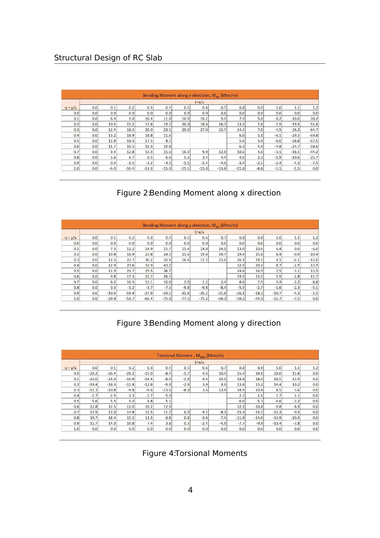
The bending moments Mxu, Myu and the torsional moment Mxyu, computed under
uniform load pu, are given in dimensionless form.Figure 2-4 shows the calculated
2
Document Page
Structural Design of RC Slab
Figure 1:Slab Geometry
bending moments and torsionalmoments by multiplying the with load and square
of slab side.
This assignment is presented in five following chapters,each provide solution to
following statements:
1. Discuss the benefits ensuing from the bi-directionalbehavior ofthe slab by
comparing the diagrams of the bending moments along sections parallel to the
edges with a beam model
2. To design the steel reinforcement with bars parallel to the slab edges accord-
ing to Wood Armer Method.Develop technicaldrawings with reinforcement
detailing and determine corner reaction and reinforcement to prevent it.
3. Determinate the values and orientation of the maximum and minimum (prin-
cipal) bending moments at point P, Q, R, and S and suggest alternative rein-
forcement layouts considering the principaldirections.Also, Compare resist-
3

Secure Best Marks with AI Grader

Need help grading? Try our AI Grader for instant feedback on your assignments.
Document Page
Structural Design of RC Slab
Figure 2:Bending Moment along x direction
Figure 3:Bending Moment along y direction
Figure 4:Torsional Moments
4
Document Page
Structural Design of RC Slab
ing and acting bending moments at these points versus the orientation of the
bending plane and comment on the effectiveness of the reinforcement layouts
considered.
4. Assess the collapse load of the slab reinforced with steelbars parallelto the
edges by using the yield line theory and comment on the the difference with
respect to the ultimate design load.
5. Identify possible improvements of the reinforcement design by using the strip
method and discuss the distinctive features of limit analysis applied to rein-
forced concrete slabs.
5
Document Page
Structural Design of RC Slab
2 Comparison of Slab and Beam model
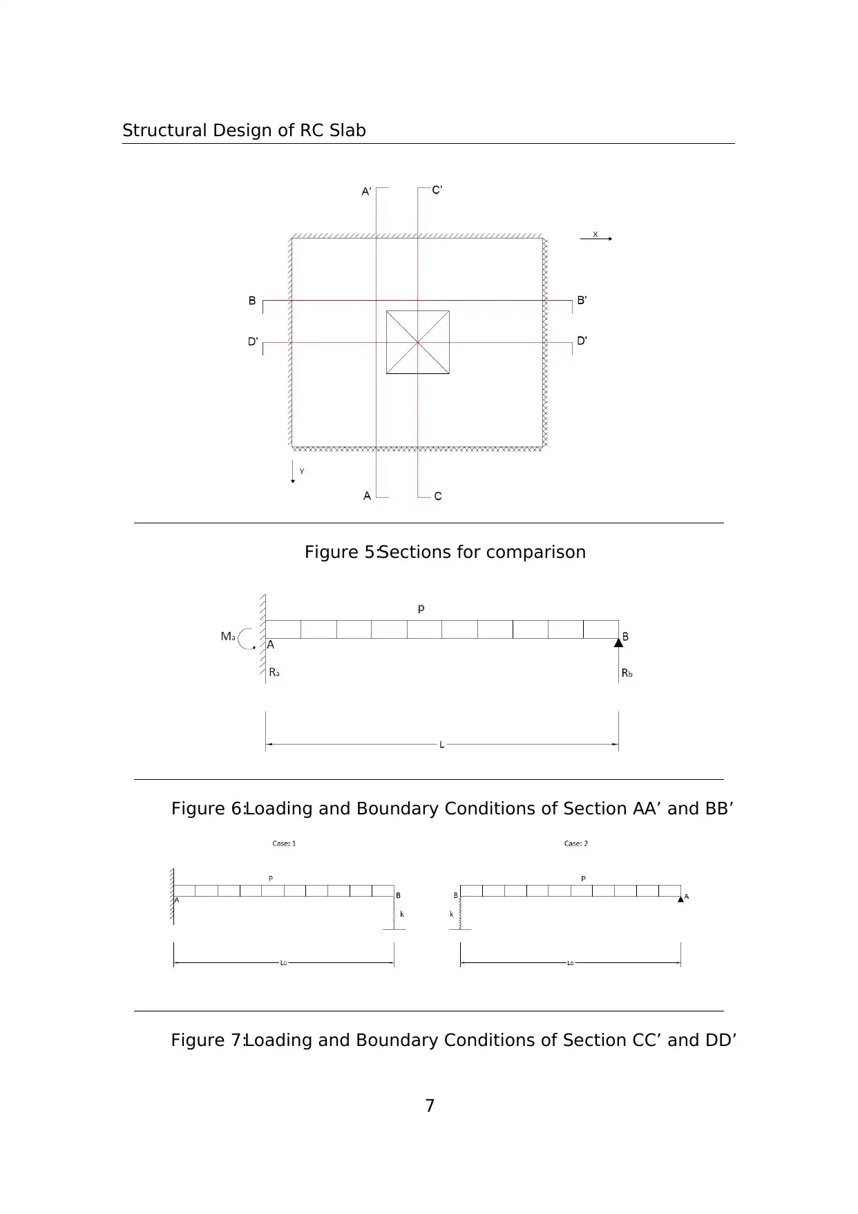
In this chapter,the bending moments along the section parallelto the edges are
compared to beam model.Four sections are chosen for comparison.These sections
are shown in Figure 5.Section AA’ (ξ = 0.4) and Section BB’(η = 0.3) are sections
of highest Myu and Mxu, respectively.The comparison of the beam with these two
sections will produce an appropriate depiction.Other two sections CC’ and DD’ are
along y- and x-direction, respectively, and passes through the center of the plate.
Section AA’ and BB’ are fixed at one end and simply supported at another end.The
bending moment for similar beam can be calculated by the methods of superposition
Figure 6 shows the loading and boundary conditions of Section AA’ and BB’.
Let’s select Rb as redundant then
Ra = pL − Rb and Ma = pL2/2–RbL
From force displacement relations for a cantilever beam, deflection at point B.
δb1 = pL4/8EI and δb2 = RbL 3/3EI
From compatibility conditions
δb1 = δb2
So, Rb = 3pL/8, Ra = 5pL/8 and Ma = pL2/8
From the reactions, Bending moment, M = p/8(5Lx − L2 4x2) is obtained.This
Moment is used for Section AA’ and BB’.
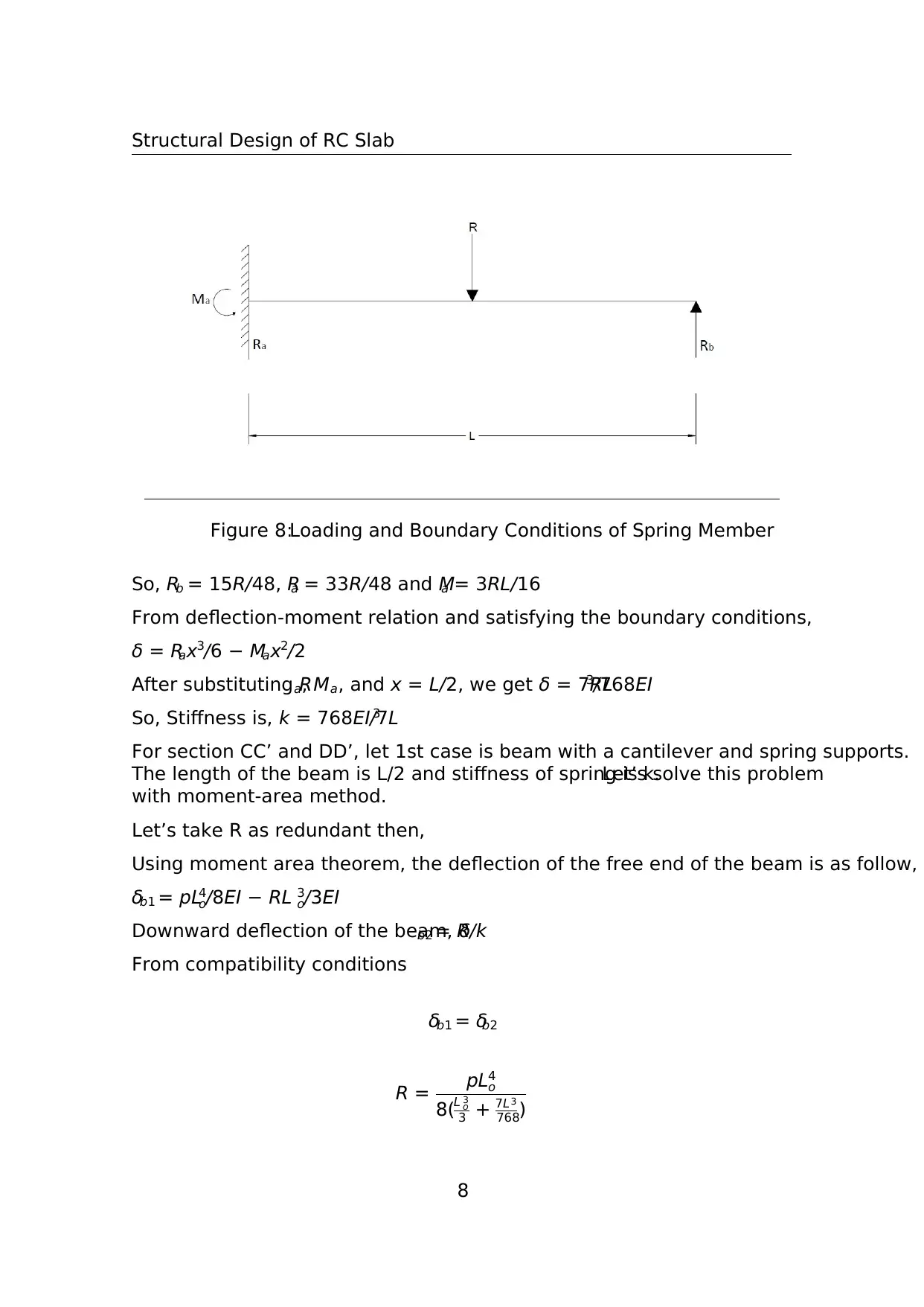
For section CC’ and DD’, we have to consider two cases as shown in Figure 7.The
first step is to calculate the stiffness of the spring.The stiffness of spring is same
as that of the center of the beam along edges of hole extended to fixed and simply
supported edges.The loading and boundary conditions of the beam are shown in
Figure 8.
Let’s use the method of superposition to calculate the deflection at the center of this
beam.
Let’s select Rb as redundant then
Ra = R − Rb and Ma = RL/2–RbL
From force displacement relations for a cantilever beam, deflection at point B.
δb1 = 5RL3/48EI and δb2 = RbL 3/3EI
From compatibility conditions
δb1 = δb2
6

Paraphrase This Document

Need a fresh take? Get an instant paraphrase of this document with our AI Paraphraser
Document Page
Structural Design of RC Slab
Figure 5:Sections for comparison
Figure 6:Loading and Boundary Conditions of Section AA’ and BB’
Figure 7:Loading and Boundary Conditions of Section CC’ and DD’
7
Document Page
Structural Design of RC Slab
Figure 8:Loading and Boundary Conditions of Spring Member
So, Rb = 15R/48, Ra = 33R/48 and Ma = 3RL/16
From deflection-moment relation and satisfying the boundary conditions,
δ = Rax3/6 − Max2/2
After substituting Ra, Ma, and x = L/2, we get δ = 7RL3/768EI
So, Stiffness is, k = 768EI/7L3
For section CC’ and DD’, let 1st case is beam with a cantilever and spring supports.
The length of the beam is L/2 and stiffness of spring is k.Let’s solve this problem
with moment-area method.
Let’s take R as redundant then,
Using moment area theorem, the deflection of the free end of the beam is as follow,
δb1 = pL4
o/8EI − RL 3
o/3EI
Downward deflection of the beam, δb2 = R/k
From compatibility conditions
δb1 = δb2
R = pL4
o
8(L 3
o
3 + 7L3
768)
8
Document Page
Structural Design of RC Slab
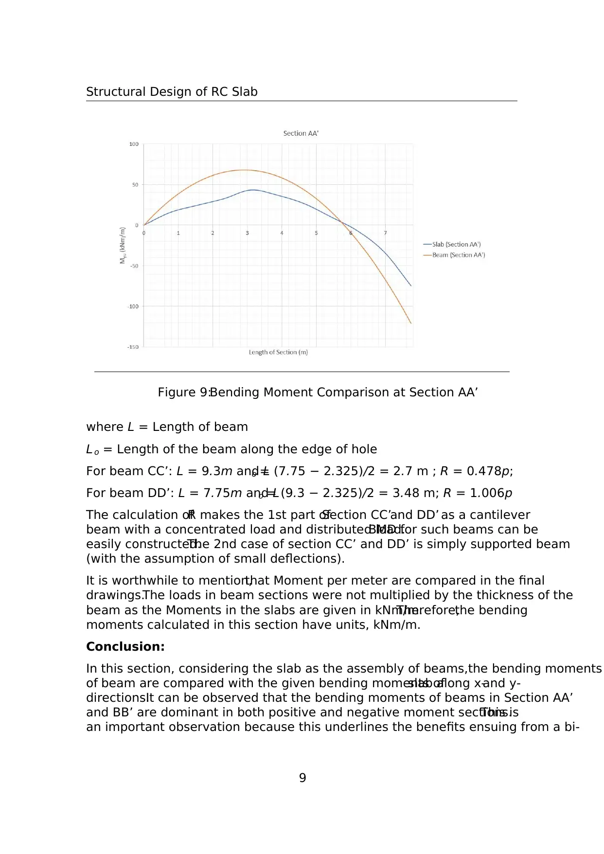
Figure 9:Bending Moment Comparison at Section AA’
where L = Length of beam
L o = Length of the beam along the edge of hole
For beam CC’: L = 9.3m and Lo = (7.75 2.325)/2 = 2.7 m ; R = 0.478p;
For beam DD’: L = 7.75m and Lo = (9.3 2.325)/2 = 3.48 m; R = 1.006p
The calculation ofR makes the 1st part ofSection CC’and DD’ as a cantilever
beam with a concentrated load and distributed load.BMD for such beams can be
easily constructed.The 2nd case of section CC’ and DD’ is simply supported beam
(with the assumption of small deflections).
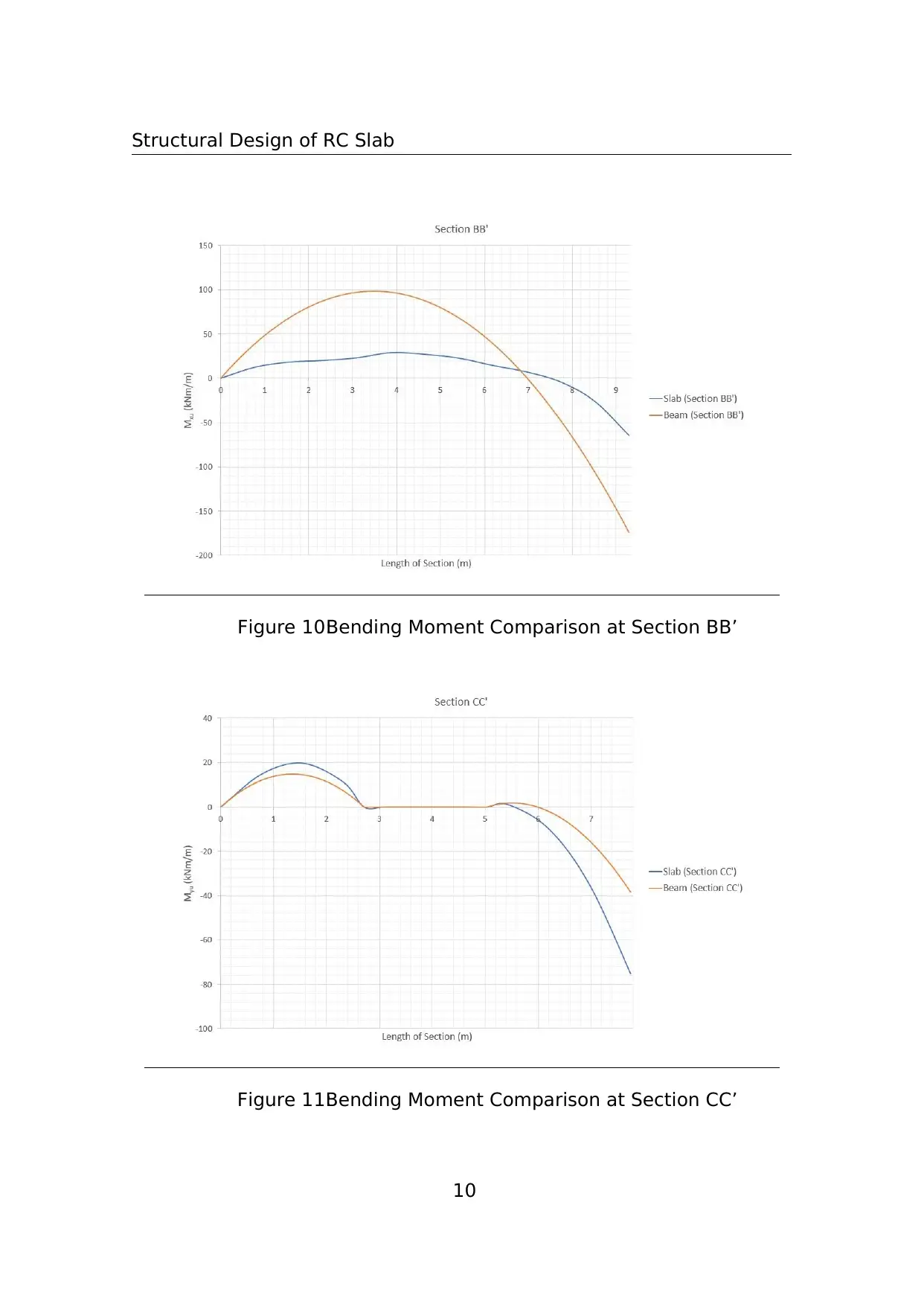
It is worthwhile to mention,that Moment per meter are compared in the final
drawings.The loads in beam sections were not multiplied by the thickness of the
beam as the Moments in the slabs are given in kNm/m.Therefore,the bending
moments calculated in this section have units, kNm/m.
Conclusion:
In this section, considering the slab as the assembly of beams,the bending moments
of beam are compared with the given bending moments ofslab along x-and y-
directions.It can be observed that the bending moments of beams in Section AA’
and BB’ are dominant in both positive and negative moment sections.This is
an important observation because this underlines the benefits ensuing from a bi-
9

Secure Best Marks with AI Grader

Need help grading? Try our AI Grader for instant feedback on your assignments.
Document Page
Structural Design of RC Slab
Figure 10:Bending Moment Comparison at Section BB’
Figure 11:Bending Moment Comparison at Section CC’
10
Document Page
Structural Design of RC Slab
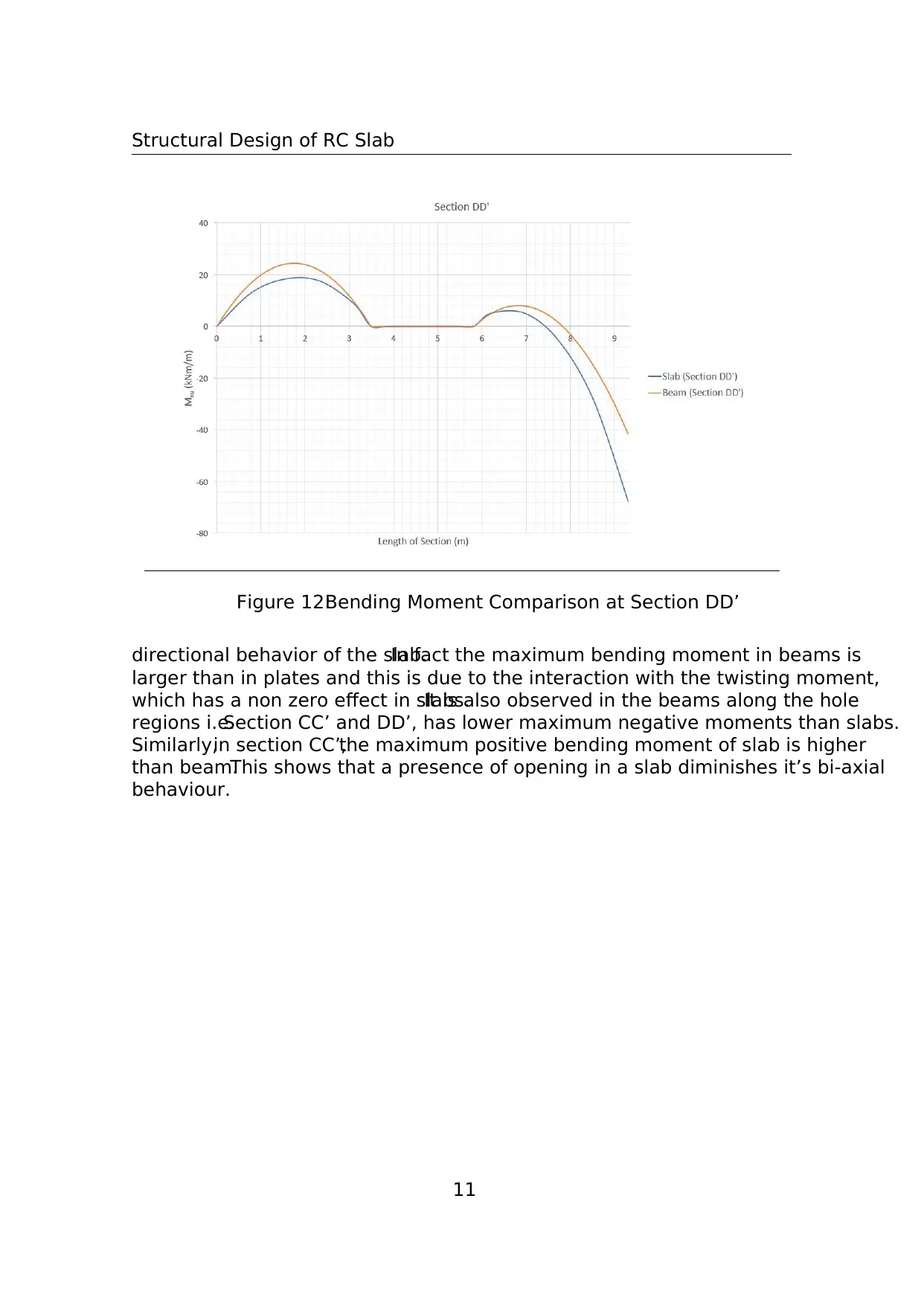
Figure 12:Bending Moment Comparison at Section DD’
directional behavior of the slab.In fact the maximum bending moment in beams is
larger than in plates and this is due to the interaction with the twisting moment,
which has a non zero effect in slabs.It is also observed in the beams along the hole
regions i.e.Section CC’ and DD’, has lower maximum negative moments than slabs.
Similarly,in section CC’,the maximum positive bending moment of slab is higher
than beam.This shows that a presence of opening in a slab diminishes it’s bi-axial
behaviour.
11
Document Page
Structural Design of RC Slab
3 Steel Reinforcement Design by Wood-Armer
Method
The design ofsteelreinforcement ofthe given slab with a centralopening is cal-
culated in this section by Wood Armer Method.The anchorage lengths and rein-
forcement for preventing corner uplift at simply supported edges are also calculated.
At the end of the section, the resisting moments are calculated and then compared
with the calculated Wood Armer Moments to discuss the validity ofthe designed
reinforcement.
Wood-Armer method is a generallower bound approach which incorporates the
torsionalmoments in the bending moments along x and y-direction.The theory
behind the Wood-Armer method is not going to discuss deeply in this assignment.
Essentially it identifies the most critical orientation of the acting bending moment,
which is used as a reference for the design ofthe reinforcement and imposing the
equality between the most critical bending moment M and the Wood-Armer resisting
moment m.The great advantage ofthis method is due to the fact that even the
twisting moment is taken into account.
The final Wood-Armer design equations are represented below and are different
according to the position of the steel bars (top or bottom)
Bottom Reinforcement:
m+
ux = Mux + Muxy
m+
uy = Muy + Muxy
If either of m+
ux or m+
uy is found to be negative, then the negative moment is changed
into zero and another moment is given as follow,
m+
ux = Mux+ | M2
uxy/M uy |
with m+
uy = 0
m+
uy = Muy+ | M2
uxy/M ux |
with m+
ux = 0
If both of m+
ux or m+
uy are found to be negative, no reinforcement is required.
Top Reinforcement:
12

Paraphrase This Document

Need a fresh take? Get an instant paraphrase of this document with our AI Paraphraser
Document Page
Structural Design of RC Slab
Figure 13:Wood Armer Moment for Bottom reinforcement along X- direction
m
ux = Mux Muxy
m
uy = Muy Muxy
If either of m
ux or m
uy is found to be positive, then the positive moment is changed
into zero and another moment is given as follow,
m
ux = Mux | M2
uxy/M uy |
with m
uy = 0
m
uy = Muy | M2
uxy/M ux |
with m
ux = 0
If both of m
ux or m
uy are found to be positive, no top reinforcement is required.
After imposing above conditions on the given bending moments and torsionalmo-
ment,m+
ux, m+
uy, m
ux, and m
uy are calculated.Figure 13-16 shows the values of
Wood Armer Moments obtained.The moments are also designed moments for the
reinforcement design of slab.
For these moments,reinforcement areas are calculated with the rectangular stress
block approximation.The following relation is used to calculate the reinforcement
area,
m+
ux = 0.9a+
x f ydd+
x
13
Document Page
Structural Design of RC Slab
Figure 14:Wood Armer Moment for Bottom reinforcement along Y- direction
Figure 15:Wood Armer Moment for Top reinforcement along X- direction
Figure 16:Wood Armer Moment for Top reinforcement along Y- direction
14
Document Page
Structural Design of RC Slab
Figure 17:Bottom reinforcement along X- direction
Figure 18:Bottom reinforcement along Y- direction
Figure 19:Top reinforcement along X- direction
15

Secure Best Marks with AI Grader

Need help grading? Try our AI Grader for instant feedback on your assignments.
Document Page
Structural Design of RC Slab
Figure 20:Top reinforcement along Y- direction
a+
x = m+
ux/(0.9fydd+
x )
The similar formula is used to calculate the a+
uy, a
ux, and a
uy.
It is assumed that the bars of diameter 14 mm are used along x- and y-direction, in
both bottom as well as top reinforcement.
The clear cover is calculated in accord to Chapter:4,Euro code:2.The structural
class S4 was chosen initially,as it is recommended in Section 4.4.1.2.However,
the class was then reduced to S3 as in accord to Table 4.3N (Member with slab
geometry).From Table 4.4N,for S3 structuralclass and XC3 exposure condition,
the clear cover of 20 mm has been chosen.
So, Clear cover, C = 20 mm
The diameter of bars, φ = 14 mm
Height of slab, h = 260 mm
Effective depth of bottom reinforcement along x- direction, d+
x = h − C − φ − φ/2 =
219 mm
Effective depth of bottom reinforcement along y- direction, d+
y = h − C − φ/2 = 233
mm
Effective depth of top reinforcement along x- direction, d
x = h−C −φ/2 = 233 mm
Effective depth of top reinforcement along y- direction, d
y = h − C − φ − φ/2 = 219
mm
Design Yield Strength of Steel fyd = 391.3 MPa
16
Document Page
Structural Design of RC Slab
So, by using the above parameters and area equations,area required for allthe
Wood Armer Moments are shown in Figure 17-20.
The minimum and maximum reinforcement areas are calculated in accord to Section
9.2.1.1, EC2.
Minimum Rebar Area
Amin = 0.26bdfctm/f yk 0.0013bd
Where , the tensile strength of concrete, fctm = 2.6 MPa [Table 3.1, EC 2]
And , width b = 1000 mm and Yield strength of steel, fyk = 450 MPa.
d = Effective depth of reinforcement
Hence,
Minimum Area of bottom rebar along x- direction, A+
xmin = 328.98mm2
Minimum Area of bottom rebar along y- direction, A+
ymin = 350.07mm2
Minimum Area of top rebar along x- direction, A
xmin = 350.7mm2
Minimum Area of top rebar along x- direction, A
ymin = 328.98mm2
Maximum Rebar Area
Amax = 0.04bh = 10400mm2
Maximum Spacing
The maximum spacings between reinforcement is calculated according to Section
9.3.1.1, EC2.
In the General Section,
For Primary Rebars, smax = min[3h, 400mm] = min[780mm, 400mm] = 400 mm
For Secondary Rebars,smax = min[3.5h, 450mm]= min[910mm, 450mm]= 450
mm
In the area of concentration loads at maximum bending,
For Primary Rebars, smax = min[h, 250mm] = min[260mm, 250mm] = 250 mm
For Secondary Rebars,smax = min[2.5h, 400mm]= min[650mm, 400mm]= 400
mm
17
Document Page
Structural Design of RC Slab
Figure 21:Sections of Bottom reinforcement along X- direction
Figure 22:Stresses and Strain in Slab section
In Figure 17-20,all the points with more than minimum requirement are marked
in red and the rest are marked in green.On the basis of the economy and practi-
cality,the sections are chosen.Figure 21,23,24,and 25 shows different regions of
reinforcements along with the provided area and required area.
Ultimate Limit State Check
To check the adequacy of provided reinforcement, the ultimate resisting moment is
calculated at severalpoints. Points P,Q, R, S, and T are chosen such that they
cover all the intersecting region of the different bottom and top reinforcement, along
x and y-direction.
In the following paragraphs,the theory of the ultimate limit state is discussed for
doubly reinforced sections (As allthe sections are doubly reinforced in the given
solution).Figure 22 can be referred for this:
18

Paraphrase This Document

Need a fresh take? Get an instant paraphrase of this document with our AI Paraphraser
Document Page
Structural Design of RC Slab
Figure 23:Sections of Bottom reinforcement along Y- direction
Figure 24:Sections of Top reinforcement along X- direction
19
Document Page
Structural Design of RC Slab
Figure 25:Sections of Top reinforcement along Y- direction
Equilibrium Equation of stress Resultants:
Cs + Cc + T = 0
Where Cc = −βξdfcd
Cs = a
0
sf ydλ0
T = asf ydλ
λ = s/ yd
λ0
= 0
s/ yd = 0
cu/ yd(1 − δ
0
)
Also, αo = 0
cu/ yd
Here we are making some assumptions:
1. Steel in Tension is yielded and hences > yd. Therefore λ = 1
2. Steel in compression is not yielded initially.Hence λ
0
< 1
So, the equilibrium equation can be written as
βξdfcd αo(1 − δ
0
)a0
sf yd + fydas = 0
Now, let’s introduce ωs, ω
0
s, and δ
0
such that
20
Document Page
Structural Design of RC Slab
ωs = asf yd/f cdd
ω0
s = a
0
sf yd/f cdd
δ0
= d
0
/d After incorporating ωs, ω
0
s, and δ
0
= d
0
/d in the equilibrium equation, and
rearranging it, we get a quadratic equation in ξ2
βξ2(ωs αoω0
s)ξ − αoδ0
ω0
s = 0
Solution of this equation is as follow
ξ = (ωs αoω0
s) +p (ωs αoω0
s)2 + 4βαoδ0ω0
s
2β
After calculating ξ,the two assumptions are checked.If they hold true,then the
next step is proceeded.In this question, both the assumptions hold true for all the
points considered for analysis (Shown in Figure 26-29).
Additionally, ductility check has been done in accord to Section 5.6.2(2), EC2, which
states that if ξ < 0.25,the section can be assumed ductile.For all the points,this
condition also holds true.
In the following paragraph, equilibrium of the moment w.r.t point of application of
Cc is written.We get the equation of resisting moment as follow,
m = T (d − 0.4ξd)–Cc(kξd − δ
0
d)
Where, k = β/2
From the above equation, resisting moments are calculated.In the Figure 26-29 all
the values of resisting moments (along x- and y- directions) and other parameters
are provided.For the design of longitudinal reinforcement, in the region cracked in
flexure,the Wood Armer moment line should be shifted over a distance ‘d’in the
unfavourable direction where ‘d’ is the effective depth of the slab.The Figure 36-43
shows the comparison of resisting and wood armer moments.
Anchorage length:
Section 8.4.3 and 8.4.4, EC2 lays down the rule of basic and design anchorage length
Basic Required Anchorage length:
lb,req = (φ/4)(fyd/f bd)
Where, Diameter of Rebar, φ = 14mm,;
21

Secure Best Marks with AI Grader

Need help grading? Try our AI Grader for instant feedback on your assignments.
Document Page
Structural Design of RC Slab
Figure 26:Positive resisting moment along X- direction
Figure 27:Positive resisting moment along Y- direction
22
Document Page
Structural Design of RC Slab
Figure 28:Negative resisting moment along X- direction
Figure 29:Negative resisting moment along Y- direction
23
Document Page
Structural Design of RC Slab
Figure 30:Bottom Reinforcement
Figure 31:Top Reinforcement
24

Paraphrase This Document

Need a fresh take? Get an instant paraphrase of this document with our AI Paraphraser
Document Page
Structural Design of RC Slab
Figure 32:Section View of reinforcement
Figure 33:Additional Reinforcement at Free end
Figure 34:Reinforcement bend at edges
25
Document Page
Structural Design of RC Slab
Figure 35:Sections for comparison of resisting and Wood Armer moments
Figure 36:Positive Mx along 1-1’
26
Document Page
Structural Design of RC Slab
Figure 37:Positive Mx along 2-2’
Figure 38:Positive My along 1-1’
27

Secure Best Marks with AI Grader

Need help grading? Try our AI Grader for instant feedback on your assignments.
Document Page
Structural Design of RC Slab
Figure 39:Positive My along 2-2’
Figure 40:Negative Mx along 1-1’
28
Document Page
Structural Design of RC Slab
Figure 41:Negative Mx along 2-2’
Figure 42:Negative My along 1-1’
29
Document Page
Structural Design of RC Slab
Figure 43:Negative My along 2-2’
Design Yield Strength of Steel fyd = 391.3 MPa
Design value of ultimate bond stress, fbd = 2.25η1η2f ctd
Here, η1 is a coefficient related to the quality of the bond condition and the position
of the bar during concreting.
It is assumed that ’good’ conditions are obtained and, hence η1 = 1.0
η2 is related to the bar diameter and here η2 = 1.0
f ctd is the design value of concrete tensile strength according to 3.1.6 (2)P, EC2.
f ctd = αctf ctk,0.05c
where αct = 1 ;
f ctk,0.05= 1.8 MPa; [Table 3.1 EC2]
And for Persistent and Transient situations, γc = 1.5 , [Section 2.4.2.4, EC2]
Therefore, fctd = 1 1.8/1.5 = 1.2 MPa
And, fbd = 2.25 1 1 1.2 = 2.7 MPa
Hence, lb,req = (14/4)(391.3/2.7) = 507.25 mm
Design Anchorage length:
30

Paraphrase This Document

Need a fresh take? Get an instant paraphrase of this document with our AI Paraphraser
Document Page
Structural Design of RC Slab
lbd = α1α2α3α4α5lb,req lb,min
Where, α1 is for the effect of the shape of Bar;
α2 is for the effect of the Concrete cover;
α3 is for the effect of the Shear Reinforcement;
α4 is for the effect of the welded transverse reinforcement;
α5 is for the effect of transverse pressure;
For Tension reinforcement:
α1 = 1 ;α2 = 1 0.15(c − φ) = 1 0.15(20 14)/14 = 0.936;α3 = 1 ; α4 = 1;
α5 = 1
lT
bd = 1 0.936 1 1 1 507.25 = 474.64mm ≥ 152.174mm
Let’s roundoff the value and take lT
bd = 500 mm
For Compression reinforcement:
α1 = 1 ; α2 = 1; α3 = 1 ; α4 = 1; α5 = 1
lC
bd = 1 1 1 1 1 507.25 = 507.25mm ≥ 152.174mm
Let’s roundoff the value and take lC
bd = 525 mm
The reinforcement detailings are shown in Figure 30-34.
Design for preventing Corner uplift:The presence ofthe twisting moment
along the edges is a relevant aspect to be considered.In fact it provides a significant
contribution.The effective support reaction on an edge is the sum of the real shear
force and of the derivate of the twisting moment in the direction of the edge.This
is due to the conversion of the twisting moment into couples of concentrated forces,
which,on the basis ofthe Saint-Venant principle,changes the stress distribution
only for a width equal to the thickness, and so it does not influence the stress field
in the interior ofthe plate.The same physicalmodelindicates the existence,at
the corners ofthe slab,of concentrated reactions,given by the sum ofthe forces
Mxy and Myx acting in the proximity of the corner.The support corner reaction is
positive if pointing upward, for assumption.The equation to be considered is
R = 2 ∗ |Mxy|
In this part,only corner P willhave uplift reaction as they are simply supported
along both the edges.
31
Document Page
Structural Design of RC Slab
Figure 44:Reinforcement at simply supported corner
R = 2 29.25 = 58.5
kNm/m
Areq = R/f yd = 149.50mm2
So, 2 bars of diameter 12 mm are used at corner to prevent corner uplift as shown
in Figure 44.
32
Document Page
Structural Design of RC Slab
4 Principal Bending Moments
We follow a Mohr’s circle formulation in order to calculate the principalbending
moments at points P, Q, R and S. This method includes transformation of a plane
stress problem into a graphical form which is useful because it enables us to visualize
the relationship between the torsionaland normalmoments at a point in a body.
Using this method, the principal bending moment values can be determined.
The following formulas are used to calculate the required principal moments,
The orientation of the principal moments is given by θ
tan(2θ) = 2Mxy
Mx My
The normal and tangential bending moments , Mn and Mnt, respectively are given
by
Mn = Mc + Mdcos(2θ) + Mxysin(2θ)
Mnt = Mdsin(2θ) − Mxycos(2θ)
where
Mc = Mx + My
2
Md = Mx My
2
The radius of the Mohr’s circle,R, is given as follow;
R =
q
M 2
d + M2
xy
The principal bending moments at a point are represented by M1 and M2 as
M1 = Mc + R
M2 = Mc R
The results for the points P (0.10, 0.10), Q (0.10, 0.90), R (1.10, 0.90) and S (1.10,
0.10) are summarized in the Figures 45.The values of 2θ are in radians while the
values of θm in the last row are converted to degrees.
The Mohr’s circles for the given points are shown in Figure 46-49.
33

Secure Best Marks with AI Grader

Need help grading? Try our AI Grader for instant feedback on your assignments.
Document Page
Structural Design of RC Slab
Figure 45:Principal Moments
Figure 46:Mohr Circle for Point P
34
Document Page
Structural Design of RC Slab
Figure 47:Mohr Circle for Point Q
Figure 48:Mohr Circle for Point R
35
Document Page
Structural Design of RC Slab
Figure 49:Mohr Circle for Point S
Figure 50:Suggested Orientation of Reinforcements
36

Paraphrase This Document

Need a fresh take? Get an instant paraphrase of this document with our AI Paraphraser
Document Page
Structural Design of RC Slab
Figure 51:Comparison of orthogonal and skew moments at point P
Figure 52:Graphical comparison of orthogonal and skew moments at point P
37
Document Page
Structural Design of RC Slab
Figure 53:Comparison of orthogonal and skew moments at point Q
Figure 54:Graphical Comparison of orthogonal and skew moments at point Q
38
Document Page
Structural Design of RC Slab
Figure 55:Comparison of orthogonal and skew moments at point R
Figure 56:Graphical Comparison of orthogonal and skew moments at point R
39

Secure Best Marks with AI Grader

Need help grading? Try our AI Grader for instant feedback on your assignments.
Document Page
Structural Design of RC Slab
Figure 57:Comparison of orthogonal and skew moments at point S
Figure 58:Graphical Comparison of orthogonal and skew moments at point S
40
Document Page
Structural Design of RC Slab
Cracks are usually formed along the maximum moments i.e.approximately along
the diagonals ofthe slab. To counteract these cracks,steelreinforcement can be
given perpendicular to the cracks.
Torsionalmoments are usually negative along the diagonaland positive along the
perpendicular direction to the diagonal.Hence top reinforcement in the corners is
given along the diagonaland bottom reinforcement in the corners is given perpen-
dicular to the diagonals.
The Figure 50 illustrates this phenomenon.As this process can be really cumbersome
practically, we stick to horizontal and vertical reinforcement in the corners for both,
top and bottom reinforcement.
We now analyze the gradation of the acting,resisting and the skew reinforcement
moments with the different angles of orientations
Acting bending Moment, Mn;
Mn = Mxcos2(θ) + Mysin2(θ) + 2Mxycos(θ)sin(θ)
Resisting Moments, m+
n and m
n are given below;
m+
n = m+
x cos2
θ + m+
y sin2
θ
m
n = m
x cos2
θ + m
y sin2
θ
For skew reinforcements, m+
ns and m
ns are given below;
m+
n = m+
n cos2
θ+θm
m
n = m
n cos2
θ+θm
Conclusion
It is observed that the acting bending moment is always lower than the positive
resisting moment and higher than the negative resisting moment.At the points
where the difference between the acting and the resisting bending moments is small
the individual resisting moments in the x and y direction at that point are used for
the design of reinforcement at that point.Looking at the graphs of the skew rein-
forcements, it can be concluded that it is an effective way of placing reinforcements,
except at point R due to the abnormalbehaviour.However this layout technique
cannot be feasible practically.
41
Document Page
Structural Design of RC Slab
5 Yield Line Analysis
The plastic hinge was introduced as a location along a member in a continuous
beam or frame at which, upon overloading, there would be a large inelastic rotation
at essentially a constant resisting moment.For slabs, the corresponding mechanism
is the Yield Line. For the overloaded slab,the resisting moment per unit length
measured along a yield line is constant as inelastic rotation occurs;the yield line
serves as an axis of rotation for the slab segment.
The Yield Line theory is derived from the generaltheory ofstructuralplasticity,
which states that the collapse load of a structure lies between two limits, an upper
bound and a lower bound of the true collapse load.These limits can be found by
the established methods.
Upper Bound Theorem:If, for a smallincrease ofdisplacement,the internal
work done by the slab, assuming that the moment at every plastic hinge is equal to
the yield moment and that boundary conditions are satisfied, is equal to the external
work done by the given load for the same small increment of displacement, then that
load is an upper bound of the true carrying capacity.
Rules for Yield Lines:
1. Yield lines are straight lines because they represent the intersection oftwo
planes.
2. Yield lines represent axes of rotation.
3. The supported edges ofthe slab willalso establish axes ofrotation. If the
edge is fixed, a negative yield line may form, providing constant resistance to
rotation.If the edge is simply supported,the axis ofrotation provides zero
resistance.
4. An axis of rotation will pass over any column support.Its orientation depends
upon other considerations.
5. Yield lines form under concentrated loads,radiating outward from the point
of application.
6. A yield line between two slab segments must pass through the point of inter-
section of the axes of rotation of the adjacent slab segments.
Once the general pattern of yielding and rotation has been established by applying
the guidelines just stated, the specific location and orientation of the axes of rotation
and the failure load for the slab can be established by either of two methods.We use
the method of virtual work.This method is based on equating the internal work
42

Paraphrase This Document

Need a fresh take? Get an instant paraphrase of this document with our AI Paraphraser
Document Page
Structural Design of RC Slab
Figure 59:Global Yield Line Pattern 1
done at the plastic hinges with an external work done by the loads as the predefined
failure mechanism is given a small virtual displacement.
Choice of a yield line pattern:
Pattern 1:
The given support, loading and geometric conditions of the slab indicate the possible
yield line patterns are chosen.
Internal work done:
The internalwork done during the assigned virtualdisplacement is found by sum-
ming the products ofthe yield moment m per unit length ofthe hinge times the
plastic rotation at the respective yield lines, consistent with the virtual displacement.
For the case of orthogonal reinforcement, the contributions from both directions are
dealt with separately as shown in the following general formula:
munθulo = X
i
(mxθxyo + myθyxo)i
Due to the virtual displacement at the intersection of the yield lines, the correspond-
ing rotations are evaluated as follows:
43
Document Page
Structural Design of RC Slab
θx = δ
0.45a
θy = δ
0.35a
The Contribution of the positive moment due to mx:
[50.966(0.35a)+42.467(0.35a)+42.112(0.233a)+50.638(0.1166a)+50.966(0.233a)]
δ
0.45a
The Contribution of the positive moment due to my:
[76.404(0.45a) + 43.503(0.45a) + 43.503(0.45a) + 66.854(0.45a)]
δ
0.35a
The Contribution of the negative moment due to mx:
[66.55(a)]δ
0.45a
The Contribution of the negative moment due to my:
[63.55(1.2a)]
δ
0.35a
Summing up the equations above and substituting a = 7.75 m, we get Wi = 806.997δ
External work done:
We = Pu
Z
w(x, y)dA
This integral can be re-written as We = Arigid (Displacement of centroid).
Thus, We = Pu Arp δG
A1 = 0.2625a2
A1 = 0.2925a2
δG1 = 2δ/5
δG2 = 16δ/39
The summation gives us the results, We = 27.028 ∗ Pu δ
44
Document Page
Structural Design of RC Slab
Figure 60:Global Yield Line Pattern 2
Energy Balance
We = Wi
We arrive at Pu = (806.997/27.028)= 29.85 kN/m2 which is greater than the
applied load Po i.e. 16.125 kN/m2
Pattern 2:
We note that the positive yield lines arising from the corners of the slab meet at a
point that is at a distance β ∗ b0 from the verticaledge where b’is the horizontal
distance from the longer edge of the slab to the edge of the hole i.e.0.45(a).
We take the graphical approach for this Yield line problem because the slab is divided
into numerous sub divisions with different resisting moments in each of them and
accounting for all these changes with varying β could be time consuming.
We first fix the value of β to 0.33
Following the same procedure as we did in the first global yield line mechanism, we
calculate
Internal work done:
Due to the virtual displacement at the intersection of the yield lines, the correspond-
ing rotations are evaluated as follows:
45

Secure Best Marks with AI Grader

Need help grading? Try our AI Grader for instant feedback on your assignments.
Document Page
Structural Design of RC Slab
θx = δ
1.1625
θy = δ
3.875
The Contribution of the positive moment due to mx:
[50.966(2.7125) + 42.46(1.1625) + 42.46(3.875) + 50.63(2.7125)+
+42.112(1.1625) + 42.112(3.875)] (δ/1.1625)
The Contribution of the positive moment due to my:
[53.4(1.1625) + 43.50(0.8138) + 53.4(0.3488) + 43.5(0.8138)+
+66.85(0.3488) + 66.85(1.1625) + 53.50(2)(2.325) + 66.85(2)(2.325)] (δ/3.875)
The Contribution of the negative moment:
66.557(7.75)(δ/1.1625) + 63.55(9.3) (δ/3.875)
By summing these equations, we get,
Wi = 1409.24δ
External work done:
V1 = V2 = Volume of half pyramids
V3 = Volume of prism
V4 = Volume of hole
Thus, V = V1 + V2 + V3V4
V1 = (1/3) (a) (0.45 ∗ a ∗ β) (δ) = 3δ
V3 = [(1/2) (a) (δ)] [b–2 (0.45 ∗ a ∗ β)] = 27.02δ
V4 = [(0.3 7.75)2] ∗ δ = 5.40δ
We = V ∗ Pu = 27.62 ∗ δ ∗ Pu
Energy Balance:
46
Document Page
Structural Design of RC Slab
Wi = We
Pu = 1409.24 ∗ δ
27.62 ∗ δ
= 51.02kN/m2
Thus, at β = 0.33, Pu = 51.02kN/m2 which is greater than the applied load Po i.e.
16.125kN/m2
We now fix the value of β to 0.5
Internal work done:
Due to the virtual displacement at the intersection of the yield lines, the correspond-
ing rotations are evaluated as follows:
θx = δ
1.74
θy = δ
3.875
The Contribution of the positive moment due to mx:
[50.966(2.7125) + 42.46(1.1625) + 42.46(3.875) + 42.112(2.5833)+
+42.46(1.2917) + 42.46(1.1625) + 50.966(0.1292) + 50.63(2.5833)] (δ/1.74)
The Contribution of the positive moment due to my:
[53.40(1.7438) + 53.4(0.5231) + 43.5(1.2206) + 43.5(1.2206)+
+66.85(0.5231) + 66.85(1.7438) + 66.85(2)(1.7438) + 50.966(2)(1.7438)] (δ/3.87
The Contribution of the negative moment:
66.557(7.75)(δ/1.74) + 63.55(9.3) (δ/3.875)
By summing these equations, we get,
Wi = 1056.29δ
External work done:
47
Document Page
Structural Design of RC Slab
V1 = V2 = Volume of half pyramids
V3 = Volume of prism
V4 = Volume of hole
Thus, V = V1 + V2 + V3V4
V1 = (1/3) (a) (0.45 ∗ a ∗ β) (δ) = 4.5δ
V3 = [(1/2) (a) (δ)] [b–2 (0.45 ∗ a ∗ β)] = 22.52δ
V4 = [(0.3 7.75)2] ∗ δ = 5.40δ
We = V ∗ Pu = 26.128 ∗ δ ∗ Pu
Energy Balance:
Wi = We
Pu = 1056.29 ∗ δ
26.128 ∗ δ
= 40.43kN/m2
Thus,at β = 0.5,Pu = 40.43kN/m2 which is greater than the applied load Po i.e.
16.125kN/m2
We now fix the value of β to 1
Internal work done:
Due to the virtual displacement at the intersection of the yield lines, the correspond-
ing rotations are evaluated as follows:
θx = δ
3.4875
θy = δ
3.875
The Contribution of the positive moment due to mx:
[50.966(2.7125) + 42.46(1.1625) + 42.46(3.875) + 42.112(1.2917)+
+42.46(2.5833) + 42.46(1.1625) + 50.966(1.4208) + 50.63(1.2917)] (δ/3.4875)
48

Paraphrase This Document

Need a fresh take? Get an instant paraphrase of this document with our AI Paraphraser
Document Page
Structural Design of RC Slab
The Contribution of the positive moment due to my:
[53.40(3.4875) + 53.4(1.0463) + 43.5(2.4413) + 43.5(2.4413)+
+66.85(1.0463) + 66.85(3.4875) + 66.85(2)(1.7438) + 50.966(2)(1.7438)] (δ/3.87
The Contribution of the negative moment:
66.557(7.75)(δ/3.4875) + 63.55(9.3) (δ/3.875)
By summing these equations, we get,
Wi = 697.66δ
External work done:
V1 = V2 = Volume of half pyramids
V3 = Volume of prism
V4 = Volume of hole
Thus, V = V1 + V2 + V3V4
V1 = (1/3) (a) (0.45 ∗ a ∗ β) (δ) = 9δ
V3 = [(1/2) (a) (δ)] [b–2 (0.45 ∗ a ∗ β)] = 9δ
V4 = [(0.3 7.75)2] ∗ δ = 5.40δ
We = V ∗ Pu = 12.6 ∗ δ ∗ Pu
Energy Balance:
Wi = We
Pu = 697.6 ∗ δ
12.6 ∗ δ
= 55.3kN/m2
Thus, at β = 1, Pu = 55.3kN/m2 which is greater than the applied load Po i.e.
16.125kN/m2.
From these 3 values of Pu for the corresponding 3 values of β, we plot a graph of β
vs Pu and set the minima of the graph as our optimal solution of β and hence Pu.
As the Yield line approach is an upper bound approach, we consider the minima of
the function as that will take us closest to the real solution.
49
Document Page
Structural Design of RC Slab
Figure 61:Variation of Pu with Beta
Figure 61 shows that the minimum accurs at β = 0.642, and the corresponsing value
of Pu = 37.67kN/m2 which is greater than Po
Local Yield Line pattern:
Localyield line failure occurs due to curtailment of reinforcement bars in the top.
The considered slap part will cause its own yield failure pattern and may cause local
failure of structures.The following procedure is followed.
Local failure pattern 1:
Note that the YL pattern is similar to that of the Global case 2.
θx = δ
0.45a
θy = δ
0.15a
Internal Work:
Wi = [42.467(0.15a) + 42.467(0.15a)]
δ
0.45
+
50
Document Page
Structural Design of RC Slab
Figure 62:Local Yield Line Pattern 1
+[53.402(0.45) + 53.402(0.45) + 2(53.402(0.45a − 0.45))]
δ
0.15
Wi = (320.412 + 28.311)δ
External Work:
We = Pu δ ∗ 0.135a2(−β/6 + 1/2)
Energy Balance:
Wi = We
Pu = 320.412 + 28.311
8.1(1/2 − β/6)
For maximum Pu, we equate dPu/dβ = 0, and we get β = 0.434 for which Pu =
111.32 kN/m2. This value is greater than the applied load i.e.16.125 kN/m2.
Local failure pattern 2:
Note that the YL pattern is similar to that of the previous case
51

Secure Best Marks with AI Grader

Need help grading? Try our AI Grader for instant feedback on your assignments.
Document Page
Structural Design of RC Slab
Figure 63:Local Yield Line Pattern 2
θx = δ
0.45a
θy = δ
0.15a
Internal Work:
Wi = [42.112(0.15a) + 42.467(0.15a)]
δ
0.45
+
+[53.402(0.45) + 53.402(0.45) + 2(53.402(0.45a − 0.45))]
δ
0.15
Wi = (401.124 + 72.691)δ
External Work:
We = Pu δ ∗ 0.135a2(−β/6 + 1/2)
Energy Balance:
52
Document Page
Structural Design of RC Slab
Wi = We
Pu = 401.124 + 72.691
8.1(1/2 − β/6)
For maximum Pu, we equate dPu/dβ = 0, and we get β = 0.57 for which Pu = 161.15
kN/m2. This value is greater than the applied load i.e.16.125 kN/m2.
Conclusion:
From the above yield line analysis, it can be seen that the designed slab has higher
load capacity than the expected design load.The design is safe for both local
and globalyield failure mechanisms.Clearly,the elastic assumptions made during
analysis stage resulted in higher reserved capacity of the reinforced concrete slabs.
Even though this is not a design method,it gives a true load carrying capacity of
the reinforced concrete slab.
53
Document Page
Structural Design of RC Slab
6 Strip Method Design of Slab reinforcement
In the last chapter, the upper bound theorem, i.e.theory of yield lines is presented
for the analysis ofreinforced concrete slab.However,it is evident that an upper
bound approach predicts equal or more than the actual bearing capacity of the slab.
Moreover, in the case of error, the analysis will be on the unsafe side.Additionally,
the method requires the initially assumed distribution of reinforcements, and hence,
resisting moments to calculate the bearing capacity of the reinforced slab.There-
fore, this method requires iteratively analysis to design the optimum reinforcements
distribution.
Hillerborg (1956) suggested a lower bound approach for the design ofreinforced
concrete slabs.He stated that an applied externalload represents a lower limit of
bearing capacity ofthe plate if,for that externalload,a distribution ofmoments
can satisfy the equilibrium as wellas boundary conditions and the slab can carry
these moments at each and every point.This method,contrary to the yield line
approach, predicts the distribution of moments, shear, and support reactions on the
safe side, hence provide designer ways to minimize reinforcements.
All the lower bound limit solutions satisfy the equilibrium equation (6.1) which
contains moments along x and y directions,torsionalmoment,and the distributed
load.
M x
x2 + M y
y2 + 2
M xy
x∂y = −p
In normal cases, the stress distribution is complicated and with a Johansen-type slab,
it is hard to eliminate torsionalmoment except for a few specialcases.However,
Hillerborg (1960),in his further work,presented a method which eliminated the
consideration oftorsionalmoments for calculating the reinforcement areas.This
method leads to a lower bound design approach,known as Strip Method.This
method attempts to coincide the stress field with the resistance moment field and
hence, design a slab with variable reinforcements.
Following the Hillerborg’s study, several researchers have used strip method in their
research works.In the further studies,the concept ofstrong bands,a strip of
the slab with considerable reinforcements and hence strength,were introduced to
dealwith the design ofslabs with openings,beamless slabs,and L-Shaped slabs
(Wood and Armer, 1968).The strip method provides designer freedom to choose the
distribution of moments between the sections in the two directions and between the
positive and negative moment sections.The designers mostly choose moments that
commensurate with one calculated by elastic theory.The similar design approach
has been adopted in this solution.
54

Paraphrase This Document

Need a fresh take? Get an instant paraphrase of this document with our AI Paraphraser
Document Page
Structural Design of RC Slab
Figure 64:Strip Distribution of Slab (Plan View)
For the given question,the distribution ofthe slab is presented in Figure.64. It
is divided into 9 strips and 4 strong bands.The two adjacent edges ofslabs are
simply supported and other two edges are fixed.The distribution of strips,loads,
and thickness of strong bands are done on the basis of slab boundary conditions and
geometry.In the strip near the corners, the load is distributed along both x and y
directions.The strips in between the adjacent fixed support as well as the adjacent
simply supported are squares and the load is equally distributed.
In the rest two corners, the 60% of load is distributed normal to cantilever edge and
40% of load is normal to the simply supported edge.This distribution is kept with
the assumption that cantilever edge can carry higher loads as compared to simply
supported edge.Due to the same assumption,the side ofcorner strip normalto
cantilever support is kept twice as that of the side normal to simply supported edge.
In the center strips, the load is assumed to be distributed along the Y-direction.
55
Document Page
Structural Design of RC Slab
Figure 65:Section A-A’
The hole is completely covered by the strong bands along allthe four edges.The
two long strong edges along y-direction (Vertical) are of thickness 60 cm.The two
short strong bands along x-direction (Horizontal) are supported by the two vertical
strong bands.The thickness ofstrong bands 3-3’and 4-4’are 50 cm and 40 cm,
respectively.The thickness of 3-3’is kept more than 4-4’as the strip attached to
the 3-3’is simply supported at another end.On another hand,the strip attached
to the 4-4’is fixed at another end,therefore the reaction on the 3-3’will be more
than 4-4’.Hence, it is intuitive to use a wider strip for 3-3’ that can accommodate
more reinforcement.
Further, in this chapter, each strip sections have been discussed as follows:
Section A-A’
In this section, the cantilever is assumed to extend to the middle of the strong band
4-4’.So the length of the cantilever is (2.313+0.2) = 2.513 m.
So, Free Cantilever Maximum Negative moment = 0.5 16.125 2.5132 = 50.896
kNm/m
Let’s consider that the presence ofa strong band reduced the maximum negative
moment by α and α is taken as 0.5 for all the sections supported by the cantilever
and strong band.
Maximum Negative Moment = 50.896 ∗ α = 25.448 kNm/m
Reaction at Strong band edge = 25.448/2.513 = 10.128 kN/m
So, for this statically determinate beam,positive moments per unit width,m =
10.128y − 0.5 16.125y2, where moment is taken from strong band edge.
56
Document Page
Structural Design of RC Slab
Figure 66:Section B-B’
For maximum m, dm/dy = 0 and yo = 0.628m and m(yo) = 3.181 kNm/m.Hence,
the maximum positive moment is 3.181 kNm/m For m = 0, y = 1.256 m, hence the
length of positive moment region is 1.256 m.
Section B-B’
This section is simply supported at both ends and, hence is a statically determinate
problem.The strip is assumed to extend to the middle of the strong band 3-3’as
same as Section A-A’. So, the length of the beam is (2.213+0.25) = 2.463 m.
So the maximum positive moment = 16.125 2.4632/8 = 12.23 kNm/m
Section C-C’
In this section,the section is assumed to extend to the middle of the strong band
1-1’.So the length of the strip is (2.892+0.3) = 3.192 m.
So, the section is simply supported beam on both ends.Let’s consider the left and
right reactions as R1 and R2, respectively.
P Fy = 0 ⇒ R1 + R2 = 0.4 16.125 1.444
P M = 0 ⇒ R2 = 0.4 16.125 1.4442/2 3.192 = 2.107 kNm/m
So, R1 = 7.207 kNm/m
So, for this statically determinate beam positive moments per unit width,m =
7.207x − 0.5 6.45 ∗ x2, where moment is taken from left edge.
For maximum m, dm/dx = 0 and xo = 1.117 m and m(xo) = 4.0264 kNm/m.
Section D-D’
57

Secure Best Marks with AI Grader

Need help grading? Try our AI Grader for instant feedback on your assignments.
Document Page
Structural Design of RC Slab
Figure 67:Section C-C’
This section has similar loading and boundary conditions as that of Section A-A’.
However,the cantilever length is as same as Strip C-C’i.e. 3.192 m,owing to the
symmetry of band about the y-axis.
So, free Cantilever Maximum Negative moment = 0.5(0.516.125)3.1922 = 41.074
kNm/m.
As per the assumption, the presence of a strong band reduced the maximum negativ
moment by α.
Maximum Negative Moment = 41.074 ∗ α = 20.537 kNm/m
Reaction at Strong band edge = 20.537/3.192 = 6.44 kN/m
So, for this statically determinate beam positive moments per unit width,m =
6.44x − 0.5 (0.5 16.125) ∗ x2, where the moment is taken from strong band edge.
For maximum m, dm/dx=0 and xo = 0.799 m and m(yo) = 2.57 kNm/m.
For m=0, x=1.596, hence the length of positive moment region is 1.596m.
Section E-E’ and Section G-G’
These sections are similar to Section C-C’in accord to boundary conditions and
loading distribution.However, the magnitude of load is 2.5 and 1.25 times the load
of section C-C’ for section E-E’ and section G-G’, respectively.
For Section E-E’
Positive bending moment = 2.5 4.0264 = 10.065 kNm/m
For Section G-G’
58
Document Page
Structural Design of RC Slab
Figure 68:Section D-D’
Figure 69:Section E-E’
59
Document Page
Structural Design of RC Slab
Figure 70:Section G-G’
Figure 71:Section F-F’
Positive bending moment = 1.25 4.0264 = 5.033 kNm/m
Section F-F’ and Section H-H’
These sections are similar to Section D-D’in accord to boundary conditions and
loading distribution.However, the magnitude of load is 2 and 1.2 times the load of
section D-D’ for section F-F’ and section H-H’, respectively.
For Section F-F’
Positive bending moment = 2 2.570 = 5.140 kNm/m
Negative bending moment = 2 20.537 = 41.074 kNm/m
For Section H-H’
Positive bending moment = 1.2 4.0264 = 3.084 kNm/m
60

Paraphrase This Document

Need a fresh take? Get an instant paraphrase of this document with our AI Paraphraser
Document Page
Structural Design of RC Slab
Figure 72:Section H-H’
Negative bending moment = 1.2 20.537 = 24.644 kNm/m
The sections I-I’, J-J’, K-K’, 1-1’, and 2-2’ are fixed at one corner and simply sup-
ported at another end.So, these sections are treated as elastic beams in this design
and the bending moment diagram for these sections is obtained from the educationa
version of RISA 2D,a StructuralEngineering Software for Analysis and Design of
beams.
Section I-I’
Positive bending moment = 9.1 kNm/m
Negative bending moment = 30.8 kNm/m
Section J-J’
Positive bending moment = 68.1 kNm/m
Negative bending moment = 121.1 kNm/m
Section K-K’
Positive bending moment = 7.5 kNm/m
Negative bending moment = 25.5 kNm/m
Section 3-3’
Strong band 3-3’ is assumed to be simply supported by the two vertical strong bands
It is also assumed to extend to the middle of Strong bands of 1-1’ and 2-2’.So, the
length of 3-3’is (2.325 + 2 0.3) = 2.925 m.The loading on strong band 3-3’is a
reaction by strip B-B’ plus the remaining uniform load on it.
61
Document Page
Structural Design of RC Slab
Figure 73:Section I-I’
Figure 74:Section J-J’
62
Document Page
Structural Design of RC Slab
Figure 75:Section K-K’
Figure 76:Section 3-3’
Hence, Total Load = 19.857 + (16.125 0.5 16.125 0.25) = 23.88 kN/m
For simply supported beam, reaction at edge is = (23.88 2.925)/2 = 34.924 kN
And, Maximum Positive Moment = 23.88 2.9252/8 = 25.538 kNm
Section 4-4’
Strong band 4-4’ has same length and similar support conditions as 3-3’.However,
total load is different due to different reaction and width of strong band.
Total Load = 10.128 + (16.125 0.4 16.125 0.20) = 13.353 kN/m & Length =
2.925 m
For simply supported beam, reaction at edge is = (13.353 2.925)/2 = 19.69 kN
And, Maximum Positive Moment = 13.353 2.9252/8 = 14.280 kNm
63

Secure Best Marks with AI Grader

Need help grading? Try our AI Grader for instant feedback on your assignments.
Document Page
Structural Design of RC Slab
Figure 77:Section 4-4’
Section 1-1’
Strong band 1-1’ is assumed as a beam between a cantilever support and a simply
supported edge.This beam supports Section C-C’, E-E’, and G-G’ along with strong
bands 3-3’ and 4-4’.The total load on 1-1’ constitutes reaction by above mentioned
strips and the remaining uniform load on it.
Total load on different section is as follows.Loads along the length ofStrip C-
C’ is [2.107 + (16.125 0.6)]= 11.782 kN/m,along the length ofstrip E-E’ is
[5.267 + (16.125 0.6)] = 14.942 kN/m, and along the length of strip G-G’ is [3.160
(16.125 0.6)] = 12.835 kN/m.Additionally,at the intersections of strip 1-1’with
3-3’ and 4-4’, reaction load of 34.924 kN and 19.69 kN, respectively, are also applied
The analysis of beam shows that,
Maximum Positive Bending Moment = 112 kNm
Maximum Negative Bending Moment = 169.1 kNm
Section 2-2’
This beam supports Section D-D’, F-F’, and H-H’ along with strong bands 3-3’ and
4-4’.The totalload on 2-2’constitutes reaction by above mentioned strips and the
remaining uniform load on it.
Total load on different section is as follows.Loads along the length of Strip D-D’ is
[6.434 + (16.125 0.6 0.5 16.125 0.3)] = 13.69 kN/m, along the length of str
F-F’ is [12.868 + (16.125 0.6 16.125 0.3)] = 17.705 kN/m, and along the lengt
strip H-H’ is [7.721 + (16.125 0.6 0.6 16.125 0.3)] = 14.493 kN/m.Additionally,
at the intersections of strip 1-1’ with 3-3’ and 4-4’,reaction load of 34.924 kN and
64
Document Page
Structural Design of RC Slab
Figure 78:Section 1-1’
19.69 kN, respectively, are also applied.
The analysis of beam shows that,
Maximum Positive Bending Moment = 112.4 kNm
Maximum Negative Bending Moment = 186.9 kNm
For these design moments,reinforcement areas are calculated with the rectangular
stress block approximation.The following relation is used to calculate the reinforce-
ment area,
m+
ux = 0.9a+
x f ydd+
x
a+
x = m+
ux/(0.9fydd+
x )
The similar formula is used to calculate the a+
uy, a
ux, and a
uy.
Figure 80 shows the calculated reinforcement area and the minimum reinforcement
for each section, similarly as in Chapter 3.With the consideration of both of them,
the reinforcement detailing for sections is shown in Figure 81-82.
65
Document Page
Structural Design of RC Slab
Figure 79:Section 2-2’
Figure 80:Design Bending Moments, Rebar Area, and Minimum Area
66

Paraphrase This Document

Need a fresh take? Get an instant paraphrase of this document with our AI Paraphraser
Document Page
Structural Design of RC Slab
Figure 81:Bottom reinforcement Detailing
67
Document Page
Structural Design of RC Slab
Figure 82:Top reinforcement Detailing
68
Document Page
Structural Design of RC Slab
Conclusion:
In the strip method design, it is observed that the calculated bending moments were
low in every section, except the strong bands.The strong bands in this section are
acting as a beam and supporting the severalsections ofslab. It is also observed
that the presence of a strip JJ’ was a good choice.In the absence of it,the strong
band 1-1’ will have high reactions due to presence of simply supported edge on the
another end.
The Strip Method design produced a totally different distribution of reinforcement as
compared to Wood Armer Method.The top and bottom reinforcement given by strip
method are concentrated along the edges ofhole. However,Wood Armer bottom
reinforcements were only concentrated along the edges of hole, the top reinforcemen
were concentrated along the cantilever edges.This distribution make sense as we
have seen in the comparison ofbeam modelwith the slab. In the Wood Armer
Design,the support conditions are changed by introduction ofbands.Hence,the
main slab has been broken into slab sections, having different boundary conditions.
This design is obtained for this particular choice of strip and load distribution.This
may change significantly for a different distribution ofloads,orientation ofstrips
and strong bands.
69
1 out of 70
circle_padding
hide_on_mobile
zoom_out_icon
[object Object]

Your All-in-One AI-Powered Toolkit for Academic Success.

Available 24*7 on WhatsApp / Email

[object Object]