Porosity Effect on the Fatigue Life of Structural Adhesives
VerifiedAdded on 2023/06/07
|54
|13433
|76
AI Summary
This article discusses the impact of porosity on the fatigue life of structural adhesives. It covers the advantages and disadvantages of adhesive bonding, classification of pores, causes of porosity, fatigue loading, and more. The article also includes a literature review and methodology section. Course code, course name, and college/university are not mentioned.
Contribute Materials
Your contribution can guide someone’s learning journey. Share your
documents today.

Poro it e ect on t e ati e li e o tr ct ral ad e i es y ff h f gu f f s u u h s v 1
POROSITY EFFECT ON THE FATIGUE LIFE OF STRUCTURAL ADHESIVES
By Name
Course
Instructor
Institution
Location
Date
POROSITY EFFECT ON THE FATIGUE LIFE OF STRUCTURAL ADHESIVES
By Name
Course
Instructor
Institution
Location
Date
Secure Best Marks with AI Grader
Need help grading? Try our AI Grader for instant feedback on your assignments.

Poro it e ect on t e ati e li e o tr ct ral ad e i es y ff h f gu f f s u u h s v 2
Table of Contents
INTRODUCTION.......................................................................................................................................4
Porosity................................................................................................................................................... 7
Positive aspects of porosity.....................................................................................................................8
Influence of porosity on tensile strength of concrete...............................................................................8
Classification of pores...........................................................................................................................10
Causes of porosity.................................................................................................................................10
Fatigue loading......................................................................................................................................10
Fatigue life.............................................................................................................................................11
LITERATURE REVIEW..........................................................................................................................11
Advantages of adhesive bonding...........................................................................................................12
Disadvantages of adhesive bonding.......................................................................................................12
Applications of adhesives in the engineering field................................................................................12
Adhesive classification and properties...................................................................................................14
Advantages of epoxy resins for civil Engineering Use..........................................................................14
Epoxy additives.....................................................................................................................................15
Properties of structural adhesives..........................................................................................................15
Fundamentals of adhesives....................................................................................................................16
Chemical fundamentals.........................................................................................................................16
Mechanics fundamentals.......................................................................................................................17
Properties of common polymer adhesives.............................................................................................17
Measurement of porosity of materials...................................................................................................18
METHODOLOGY....................................................................................................................................20
Talk a summary about THUSHARA work and variation in the results.................................................20
Testing Conducted.............................................................................................................................24
The images and the process of taking these images...............................................................................29
Talk about the available software and why you chose a specific one....................................................31
Avizo 3 D..........................................................................................................................................32
Avizo 3D on Porosity and permeability of fibre reinforced concrete,....................................................33
MIPAR Image...................................................................................................................................34
Image J software................................................................................................................................37
Talk about the process of measuring the porosity in details...................................................................40
Porosity and Permeability tests..................................................................................................................42

Poro it e ect on t e ati e li e o tr ct ral ad e i es y ff h f gu f f s u u h s v 3
Advantages of the possibility of adhesive bonding....................................................................................44
Result........................................................................................................................................................ 45
Conclusion.................................................................................................................................................45
Bibliography..............................................................................................................................................47
Poro it e ect on t e ati e li e o tr ct ral ad e i es y ff h f gu f f s u u h s v 4
INTRODUCTION
Structural adhesives are categorized in consideration to their chemistries hence they
possess capabilities of overlapping shear strengths that approximately exceeds a thousand psi
when exposed in metal bonding under room temperature testing. Despite the existence of
hybrids, structural adhesives majorly constitute acrylic, epoxy, and urethane.
According to studies carried out by a good number of researchers, it is realized that
structural adhesives are commonly utilized in applications that demand durability as a key factor.
A structural adhesive contains significant advantages compared to mechanical and fusion
fastening leading to its wide application (Alton, 2012, p. 678). Nevertheless, structural adhesives
aides in reducing the average weight of the components while increasing its durability and at the
same time providing significantly increased or larger latitude of design. The above-mentioned
benefits associated with structural adhesives are achieved with limited machine requirements
which generally less costly compared to utilization of their Media of fixation. In addition,
structural adhesives are also accompanied by advantages relating to aesthetics involving lines
which are of high cleanliness and lack nails that protrude marks of welds and rivets.
Substrate formulations are now in wide existence in varying capacities ranging from
steel, copper, and aluminum and not forgetting the low energy surface plastics, glass, woods,
rubber and masonry in general (Cook, 2014, p. 097). These substrates are the commonly utilized
in the car manufacturing sector where durability forms a higher consideration in relation to
performance and consistency unlike the soon loosening or failing of the mechanical fixings.
In the partial formation of the structure of load bearing, joining of the two involved
surfaces are achieved through the utilization and designing of structural adhesives. This is
obtained through the application of 1000psi strength of overlap shear. It comprises two distinct
Secure Best Marks with AI Grader
Need help grading? Try our AI Grader for instant feedback on your assignments.
Poro it e ect on t e ati e li e o tr ct ral ad e i es y ff h f gu f f s u u h s v 5
and separate elements that initiate the process of curing when at room temperature after being
mixed in a nozzle of the applicator or rather a static mixer.
Full bond strength in one part adhesives is normally obtained through heat curing. During
the provision of bonding of higher strength, they might lack toughness and flexibility as a two-
part adhesive. They can too be made less attractive by the cost of heat curing. In addition, an
adhesive of Epoxy normally offers the best in relation to resistance to temperature and strength.
Nevertheless, they are too considered perfect infilling of voids hence enhancing rigidity and
noise reduction when performing applications relating to the manufacture of the turbine blade.
On the other hand, varieties of substrates are obtained from acrylic adhesives which
include the hard to bond plastics together with oily metals in general (Duan, 2016, p. 563). The
high strength bonding is obtained minus the preparation of the surface required for the epoxies
and urethanes. Bead on bed adhesives is generally two-part products of acrylic where a single
element is applied to a single substrate. The duo is then made to combine hence finalizing the
elimination of mixing.
Urethane adhesives are less costly adhesives though possess a higher impact resistant
two-part products while enhancing faster curing up to an elastic band when utilized in
applications that require no similar materials. Most of the structural adhesives are usually in
possession of solvents except products of urethane. The solvents perform a crucial role on the
substrate in the stage of the specification.
With an aim of ensuring safety in the area of application, adhesives in possession of
solvents require higher PPE outlay and systems of air extraction (Frank, 2014, p. 239). Solvents
in adhesives also have impacts on the chemical composition of the substrates of plastics leading
Poro it e ect on t e ati e li e o tr ct ral ad e i es y ff h f gu f f s u u h s v 6
to stress cracking. Strong odors are emitted from adhesives of acrylic and epoxy which might
eventually become dangerous to the health of the operators when they get exposed to it for a
longer duration of time.
In the long run, the choice of the eventual product will solely rely on the desired
durability, ability to stretch, resistance to creep, environment, and heat. A proper specification of
the least costing adhesive needs to be conducted in respect to the desired performance
expectations hence products life is made shorter with poor adhesive strength selection leading to
a general reduction in the confidence of a customer or consumer thus eventual loss of future
orders.
Over specification. It is similarly destructive to assume that an adhesive that stronger is
eventually the best is another misleading notion as this would result to points of stress since it
might not q accountable to the thermal expansion which generally motivates the product's
potential of failure.
Heat boundaries and extremes (Geiger, 2017, p. 998). Softening and mechanical properties loss
that is originally required in maintaining enough and reliable bonding is achieved usually with
heat above 150 degrees.
Porosity
Porosity is also known as a void fraction. It refers to the intensity of voids or spaces
existing in a material. It is normally measured as a fraction of the voids volume over the average
totals of the volume ranging from 0 to 1 or similarly as a percentage of between 0-100percent.
There exist various ways of measuring or determining the porosity in a substance. They include
the industrial CT scanning among very many more. Most materials exposed to porosity and
Poro it e ect on t e ati e li e o tr ct ral ad e i es y ff h f gu f f s u u h s v 7
voids risks a degradation property (Gerwick, 2014, p. 1467). The tensile behaviour of materials
in possession of voids or porosity is normally exhibited by the large reduction in ductility and
strength against consistently increasing the level of porosity.
Up to now, the characteristics of pervious concretes have been examined in numerous
research facilities, including blending plan, preservation strategy, porosity characteristics, quality
and toughness, Compared with conventional or common concrete, pervious concrete has an sum
of porosity and pore structure highlights, which have been demonstrated to have an incredible
impact on the properties of pervious concretes Montes prescribed utilizing the water relocation
strategy, based on Archimedes buoyancy guideline, to get porosity. Researchers like Neithalath
utilized picture investigation to analyse the pore structure highlights of pervious concrete. The
porousness of pervious concrete is tall due to the nearness of tall porosity, and the test strategies
of the porousness coefficient are particularly critical Kayhanian utilized a National Centre for
Black-top Technology’s (NCAT) falling head permeameter to assess the penetrability coefficient
of pervious concrete.
Montes assessed penetrability by employing a falling head permeameter framework. The
system may enlist the full volume streaming out of the porous fabric per moment. At the same
time, Jiang Zhengwu and Yang showed that porosity, W/C, total cement proportion, and total
estimate were the most components impacting the penetrability and quality of pervious concrete.
William considered the impact of vertical porosity conveyances on the penetrability coefficient.
Since of the moo quality of the pervious concrete arranged by common materials and strategies,
different admixtures and fine totals were presented to extend the application scope of pervious
concrete. Yang and Jiang utilized fine totals, natural intensifiers, and optimized blend extents to
Paraphrase This Document
Need a fresh take? Get an instant paraphrase of this document with our AI Paraphraser
Poro it e ect on t e ati e li e o tr ct ral ad e i es y ff h f gu f f s u u h s v 8
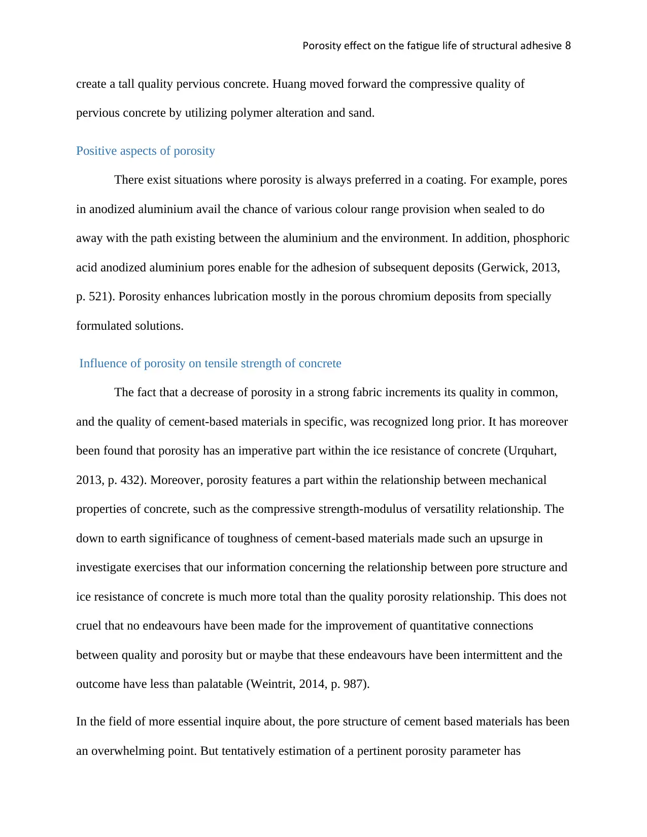
create a tall quality pervious concrete. Huang moved forward the compressive quality of
pervious concrete by utilizing polymer alteration and sand.
Positive aspects of porosity
There exist situations where porosity is always preferred in a coating. For example, pores
in anodized aluminium avail the chance of various colour range provision when sealed to do
away with the path existing between the aluminium and the environment. In addition, phosphoric
acid anodized aluminium pores enable for the adhesion of subsequent deposits (Gerwick, 2013,
p. 521). Porosity enhances lubrication mostly in the porous chromium deposits from specially
formulated solutions.
Influence of porosity on tensile strength of concrete
The fact that a decrease of porosity in a strong fabric increments its quality in common,
and the quality of cement-based materials in specific, was recognized long prior. It has moreover
been found that porosity has an imperative part within the ice resistance of concrete (Urquhart,
2013, p. 432). Moreover, porosity features a part within the relationship between mechanical
properties of concrete, such as the compressive strength-modulus of versatility relationship. The
down to earth significance of toughness of cement-based materials made such an upsurge in
investigate exercises that our information concerning the relationship between pore structure and
ice resistance of concrete is much more total than the quality porosity relationship. This does not
cruel that no endeavours have been made for the improvement of quantitative connections
between quality and porosity but or maybe that these endeavours have been intermittent and the
outcome have less than palatable (Weintrit, 2014, p. 987).
In the field of more essential inquire about, the pore structure of cement based materials has been
an overwhelming point. But tentatively estimation of a pertinent porosity parameter has
Poro it e ect on t e ati e li e o tr ct ral ad e i es y ff h f gu f f s u u h s v 9
demonstrated to be greatly troublesome in cement-based materials, since of the uncommon
character of the hydration items shaped (Watson, 2013, p. 1211). Thus the comes about gotten
will depend not as it were on the measuring rule but too on the drying strategy utilized earlier to
the porosity estimations. But indeed with these issues fathomed, an association between the
porosity and quality needs to be established. The impact of porosity on the quality of cement-
based fabric has as of now been examined. Taking an empirical approach, powers was able to
infer a condition which relates the compressive quality of mortar 3d shapes to a work of the gel
space ratio.
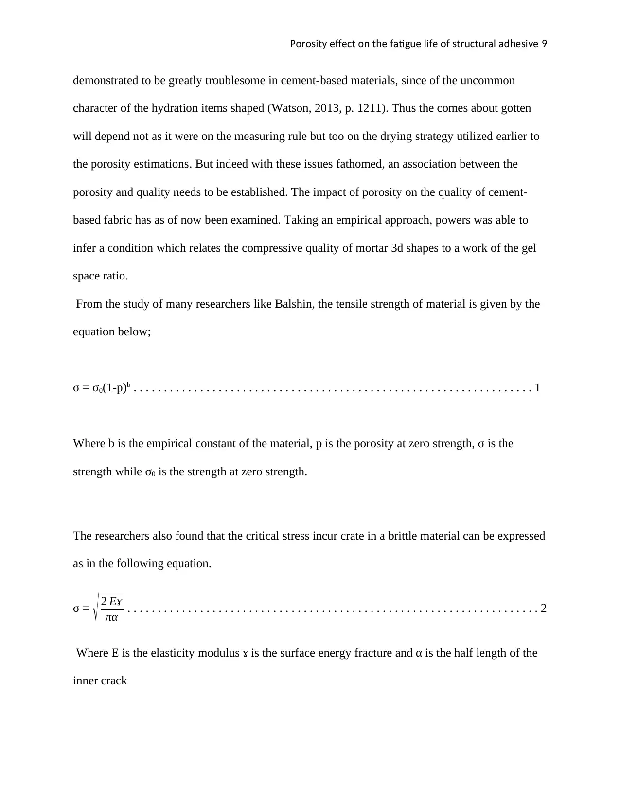
From the study of many researchers like Balshin, the tensile strength of material is given by the
equation below;
σ = σ0(1-p)b . . . . . . . . . . . . . . . . . . . . . . . . . . . . . . . . . . . . . . . . . . . . . . . . . . . . . . . . . . . . . . . . . . 1
Where b is the empirical constant of the material, p is the porosity at zero strength, σ is the
strength while σ0 is the strength at zero strength.
The researchers also found that the critical stress incur crate in a brittle material can be expressed
as in the following equation.
σ = √ 2 Eɤ
πα . . . . . . . . . . . . . . . . . . . . . . . . . . . . . . . . . . . . . . . . . . . . . . . . . . . . . . . . . . . . . . . . . . . . 2
Where E is the elasticity modulus ɤ is the surface energy fracture and α is the half length of the
inner crack
demonstrated to be greatly troublesome in cement-based materials, since of the uncommon
character of the hydration items shaped (Watson, 2013, p. 1211). Thus the comes about gotten
will depend not as it were on the measuring rule but too on the drying strategy utilized earlier to
the porosity estimations. But indeed with these issues fathomed, an association between the
porosity and quality needs to be established. The impact of porosity on the quality of cement-
based fabric has as of now been examined. Taking an empirical approach, powers was able to
infer a condition which relates the compressive quality of mortar 3d shapes to a work of the gel
space ratio.
From the study of many researchers like Balshin, the tensile strength of material is given by the
equation below;
σ = σ0(1-p)b . . . . . . . . . . . . . . . . . . . . . . . . . . . . . . . . . . . . . . . . . . . . . . . . . . . . . . . . . . . . . . . . . . 1
Where b is the empirical constant of the material, p is the porosity at zero strength, σ is the
strength while σ0 is the strength at zero strength.
The researchers also found that the critical stress incur crate in a brittle material can be expressed
as in the following equation.
σ = √ 2 Eɤ
πα . . . . . . . . . . . . . . . . . . . . . . . . . . . . . . . . . . . . . . . . . . . . . . . . . . . . . . . . . . . . . . . . . . . . 2
Where E is the elasticity modulus ɤ is the surface energy fracture and α is the half length of the
inner crack
Poro it e ect on t e ati e li e o tr ct ral ad e i es y ff h f gu f f s u u h s v 10
Classification of pores
Pores are majorly grouped into two distinct groups namely:
1. bridged pores and
2. transverse pores
Causes of porosity
A pore is generated or rises in very many ways. They include;
mix up on the basis of the metal
screening of the surface that needs to be coated
inadequate conditions during deposition
destruction and damage after plating
Fatigue loading
This mainly refers to a material being made weaker through consistent application of
loads (Hamed, 2016, p. 875). Fatigue normally happens when a material is exposed to regular
and consistent loading and unloading. Formation of cracks starts to form whenever the loads
surpass a certain degree or intensity at the regions where the stress concentration is highest, for
example, the joints. With a gradual increase in the crack size, the material eventually fractures
after the crack reaches the optimum point. Fatigue life is thus affected by the shape of the
structure shape i.e. sharp corners and square holes motivates local stresses making the starting
points of fatigue cracks whereas transitions that are smooth and round holes would improve the
fatigue strength of the same structure.
Secure Best Marks with AI Grader
Need help grading? Try our AI Grader for instant feedback on your assignments.
Poro it e ect on t e ati e li e o tr ct ral ad e i es y ff h f gu f f s u u h s v 11
Fatigue life
This is defined as the quantity of cycle stress of a specific material that it can sustain or
withstand before the material can fail in a categorical nature (Hardyman, 2016, p. 029). In
relation to materials such as titanium and aluminium, there exists a known and predictable value
of stress intensity that before the stress reaching it, the material would not fail for any random
cycle number. This limit is commonly known as fatigue limit or strength of fatigue.
Characteristics of fatigue
it is highly related to stresses of tensile though fatigue cracks arise from the loads that are
compressive in nature
Fatigue life becomes shorter with greater stress application range.
Fatigue process commences with dislocation movements present at the microscopic level
in alloys of metals.
It possesses degrees of randomness
LITERATURE REVIEW
Structural adhesives are generally compositions of monomer which polymerizes to give
out strong and rigid adhesives used forming joints for bearing loads (Harinder, 2010, p. 998).
There exists both merits and demerits of using adhesives as a means of joining materials and
surfaces hence the need to adopt alternative adhesives which possess added advantages in
providing a long-term joint stability and durability.
Advantages of adhesive bonding
Adhesive bonding possess the ability to put together or join different materials and
surfaces
Poro it e ect on t e ati e li e o tr ct ral ad e i es y ff h f gu f f s u u h s v 12
It requires minimal or totally no need of open flames or rather high input of energy in
terms of heat
Disadvantages of adhesive bonding
It requires prior treatment of the surface
It possesses very poor resistance to increased temperatures or heat
Some adhesives contain dangers relating to them being toxics and highly flammable
hence being a source of danger to the entire public or users
It lacks assurance of long-term durability
Applications of adhesives in the engineering field
Adhesives are used in the aerospace sector with an aim of replacing mechanical fasteners
through use of adhesive stems with an intention of prolonging the life of the aircraft and
reduction the cost of maintaining the aircraft (Hassani, 2015, p. 765). Example of this
application is the reinforcement of most modern military aircrafts carbon fiber airframes plastics
with adhesives. Another application is where the temperature of operation ranges from -80-
80degrees together with severe salt spraying conditions may be intense.
Adhesives are again used in the construction of buildings, for example, resinous grouts
used in bolts anchoring and ties, attachment and joining of the inside building panels together
with elements, brick slips attachment to concretes and eventually the joints between units of
precast concrete.
In civil engineering, polyesters that are not saturated, polyurethanes together with acrylics are
significant in the in the applications of adhesives thermosetting (House, 2013, p. 395). In non-

Poro it e ect on t e ati e li e o tr ct ral ad e i es y ff h f gu f f s u u h s v 13
structural situations, epoxy stands as the main material candidate. Examples of non-structural
situations are:
Membranes of waterproofing on the decks of the concrete bridge.
Layers of skid resistance on the road and other needful surfaces
Formulations of low viscosity used in the injections and filling of cracks
New concretes bonding to the old ones
Examples of adhesives in a semi-structural manner include;
Ropes, wires, and anchors of strands
Fixings of steel in concrete or rock
Structures of segmental precast for example bridges where epoxides have been widely
used in the past as a medium of distributing stress through a waterproof medium (Joseph,
2013, p. 752).
Examples of adhesives in a structural manner include the following:
Glulam which entails an arch of bonded adhesives
A bonded external plate reinforcement used in the strengthening of the existing structures
of concrete
Concrete decks or rather bonded composite steel and
Connections of structural steel works
Adhesive classification and properties
Engineering and non-engineering adhesives
Adhesives are majorly grouped as either inorganic or organic adhesives
Paraphrase This Document
Need a fresh take? Get an instant paraphrase of this document with our AI Paraphraser
Poro it e ect on t e ati e li e o tr ct ral ad e i es y ff h f gu f f s u u h s v 14
The cyanoacrylates are only part of the wider range of acrylic adhesives now on the market
(Krul, 2013, p. 532). Nevertheless, the acrylics show potential for providing an alternative source
of structural adhesive to epoxy resin in the future, less toxic.
The epoxies and polyesters, together with acrylics, polyurethanes and synthetic polymer
lattices will be discussed.
Advantages of epoxy resins for civil Engineering Use
high surface activity and good wetting properties for a variety of substrates
may be formulated to have a long open time
high cured cohesive strength: joint failure may be dictated by adherend (concrete)
strength
may be toughened by the inclusion of a dispersed rubbery phase
lack of by-products from curing reaction minimizes shrinkage and allows the bonding of
large areas with only contact pressure
low shrinkage compared with polyesters, acrylics, and vinyl types; hence residual
bondline strain in cured joints is reduced
low creep and superior strength retention under sustained load (Leonard, 2013, p. 874).
can be made thixotropic for application to vertical surfaces
able to accommodate irregular or thick bondline
may be modified by selection of base resin and hardener, application of other polymers
addition of surfactants, fillers, and other modifiers
relatively affordable
limited alkaline presence
Poro it e ect on t e ati e li e o tr ct ral ad e i es y ff h f gu f f s u u h s v 15
Epoxy additives
Fillers: often simply reduce cost although they may also assist in gap filling, reduction of creep,
reduction of the exotherm, corrosion inhibition and fire retardation. In general, fillers are inert
materials which may be organic or inorganic.
Properties of structural adhesives
A good number of adhesives are being used in the design of optical instruments and
manufacture (Leonard, 2013, p. 390). They too are used in the replacement of screws clamps,
rivets and other types of fasteners. They are used in the bonding of structures and works as a
crucial element in assembling instead of as a separating entity. Structures which are bonded are
normally of less weight, cheaper in cost and eventually simple to assemble when compared to
those that are made through mechanical methods.
Bonded structures also fairly distribute stresses uniformly and possess reliable flexibility
features than the mechanical fasteners. The above properties are always very significant in the
applications entailing larger force4sof mechanical or rather during the need of damping.
Polymers are the commonly used type of adhesive material (Lewis, 2014, p. 951). Others include
metals, powders of inorganic glass and other many more.
Fundamentals of adhesives
Joining parts is the common and basic duty of adhesives. They have perfectly offered
engineers a better option to the native methods of joining structures and surfaces such as
welding, soldering, and bolting. An example includes the need for putting together a brittle that
is notch sensitive and intolerant to hole of bolts i.e, glasses, composites of engineering and
ceramics.
Poro it e ect on t e ati e li e o tr ct ral ad e i es y ff h f gu f f s u u h s v 16
Chemical fundamentals
Commercial adhesives chemistry of polymerization is normally very complex, a catalyst or
rather a linking agent is usually introduced with an aim of triggering the reaction of
polymerization of the base material and proceed to cure the adhesive. There exist to methods of
cure system (Meissner, 2017, p. 631). They are namely:
Two part system which entails the catalyst being mixed with into the base material a
moment slightly before use.
One part system. Water vapour acts as the catalyst and it is introduced to the base
material through ambient air exposure.
The one part cure system involving diffusion of the catalyst via the bond requires for a
period of about a year for the complete curing of the bond. Nevertheless, the system of Two part
cure consistently and uniformly across the bulk hence the most reliable for the thick bond
sections. Reaction products are released by both the two and one part cure systems (Mouton,
2012, p. 812). These products may be corrosive in nature such as acetic acids or the flammable
methanol.
It is of great importance for an individual to read carefully manufactures instructions on how
a particular adhesive should be handled in order to avoid reversion or rather a depolymerization.
This happens whenever reaction products are not removed at the desired time hence making slow
the curing reaction and eventually leading to the self-reverse of the entire process. This brings
about the concept of ventilation during the curing process.
The properties relating to interface possess a general effect on the strength of the bonds
existing between substrates and adhesives (O'Hagan, 2010, p. 520). This is normally regulated
Secure Best Marks with AI Grader
Need help grading? Try our AI Grader for instant feedback on your assignments.
Poro it e ect on t e ati e li e o tr ct ral ad e i es y ff h f gu f f s u u h s v 17
through the chemistry of the surface. During the process of cure, a complete property of adhesion
normally generates days or at times hours after visibility of bulk properties. It is always safe to
consider the cleanliness of cleaning materials and solvents since the chemistry of the surface is
commonly susceptible to tracking molecular compounds quantities. In addition, small quantities
of molecular compounds are always present in the commercial adhesives with an aim of
promoting adhesion.
Mechanics fundamentals
Certain adhesive strengths are normally described as stress at rupture. Propagation of damage
via the bond is what is commonly known as rupture (Pal, 2011, p. 831). The bond frequently
raptures in the event that the damage accumulates beyond the critical level. Damage to the
adhesive bond involves various categorical mechanisms which include:
Micro cracks or micro cavities growth and initiation process
Discrete crack development and growth
Properties of common polymer adhesives
Acrylics
Acrylated urethanes form the most common type of acrylated polymers. It is widely
available in the form of one and two part. They normally generate bonds that are strong and
durable to various types of substrates. Some of the significant features of polyurethane systems
entail a reliable flexibility capability, resistance to abrasion, extraordinary physical strength
together with properties relating to gap filling (Pesutich, 2017, p. 631). They are commonly used
in bonding surfaces and elements that are no rigid due to their inherent flexibility.
Poro it e ect on t e ati e li e o tr ct ral ad e i es y ff h f gu f f s u u h s v 18
Cyanoacrylate
This is a single component adhesive that cures when exposed to moisture of alkaline and
substances that are ionic in nature present in most of the surfaces at room temperature.
Application of a surface activator or catalyst is usually necessary to speed up the process of
polymerization. They normally function to the optimum on a smooth and a surface that is closely
spaced due to their low viscosity in nature (Rausand, 2013, p. 600). They possess advantages of
being fast and easy to use since they do not demand any introduction of heat or increased
temperatures and mixing but rather pressure introduction to in order to achieve a performance
that is durable in nature. It also has a shorter time of cure.
Measurement of porosity of materials
Porosity is generally the intensity of spaces or voids present in a material. It can also be
described as a fraction of voids volume against the total volume .it normally ranges from 0 to 1
or either 0-100% in terms of percentage. There exist various distinct methods of testing voids in
a material (Robert, 2011, p. 302). They include industrial CT scanning. Additionally, voids can
be measured through the following methods:
Direct methods. Relates to the identification of the bulk volume of a porous sample of a
material proceeded by determination of material skeletal volume minus pores. This can
be summarised by the below formulae.
Average volume-volume of the material =Volume of the pore
Optical methods (Shroder, 2011, p. 208). Relates to finding the material are against the
area of pores observable on the microscope porous media with random structure possess
equal areal and volumetric porosities
Poro it e ect on t e ati e li e o tr ct ral ad e i es y ff h f gu f f s u u h s v 19
Method of Computed tomography. this employs the use of industrial CT scanning
Methods of imbition. This entails immersion of the porous material in a vacuum in
presence of a fluid intended to wet the pores.
Method of evaporating water (Sinopoli, 2015, p. 097). This is summarised by the
formulae, total water volume-left water volume after soaking=volume of the pore
The intrusion of mercury porosimetry.
Method of gas expansion and eventually
Cryoporometry and thermoporosimetry
METHODOLOGY
Talk a summary about THUSHARA work and variation in the results
Fokker started utilizing adhesive holding (By help of cement) in the year 1915,
continuing the way for different producers. In 1940, adhesive of cements was used on competes
of timber for the DH 98 airplane. Within the year 1960s, the aviation firm too started using
cement holding innovation, persuaded it was an ideal solution for the make of resistant
structures, lightweight. Beneath steady progression, cement bonding also started utilizing in
gracious flying, where high operation grounded epoxy tars which are presently extensively
utilized. As an illustration, Aviation started cement bonding in the year 1972. The aviation firm
Paraphrase This Document
Need a fresh take? Get an instant paraphrase of this document with our AI Paraphraser

Poro it e ect on t e ati e li e o tr ct ral ad e i es y ff h f gu f f s u u h s v 20
presently has more than 345 bonding structures. Hence, the long run of the cement adhesive is
promising, the display require for the way superior and execution of the materials keeping
request tall for the innovation (Yue, 2014, p. 201).
Concocting modern uses of cement bonding grounded on the simultaneous problems is
anticipated (Leeming, 2014, p. 211). Alongside the other firms, construction firm has too chose
the uses of structural cements so as to reinforce and retrofit the civil material, as retrofitting and
fortifying of present concrete and steel material has come progressively in focus of centre in the
previous decades. All over throughout the globe there are offices suggested for transport and
living (Amstock, 2011, p. 2012). The structures are of diverse operation and diverse superiority,
but all these materials are coming to conclusion of their planned benefit life and breaking down
over a specific time frame.
Several reinforcing strategies have been created in structural firm, from the 1960’s
adhesive of steel plates having epoxy have been hone so as to reinforce or repair buildings and
bridges in numerous nations like France, South Africa, Switzerland, France, Belgium, Japan,
UK, Australia and Portland. A broad review was done by Donita on the applications and research
based on steel plate holding reinforcing strategy (Adams, 2015, p. 431). This paper expressed
various uses of steel plate adhesive and depicted their bonding prepare counting the strategies for
planning the holding surface.
Some of the essential recognized uses of fortifying utilizing epoxy adhesive plates were
executed in the year 1964 in Durban, when the desired quantity of strengthening steel in a solid
beam was accidentally excluded in the construction stage that is situated in a novel apartment
complex (Allen, 2016, p. 1211).
Poro it e ect on t e ati e li e o tr ct ral ad e i es y ff h f gu f f s u u h s v 21
The plates of steel got to be outlined in a way where the failure occurring need to be
preferably a pliable failure that is discernible in advance instead of a sudden impact shear-bond
failure in which the failure is unusual (Dillard, 2011, p. 211). Despite the reality which this
retrofitting strategy has basically been executed on the strong members. (Sadek, 2012, p. 2101).
In contrast to the ordinary plates which are welded, the cement reinforced plates of steel
expanded the weakness life of the structure by a factor of 20. The utilization of Close Surface
Mounted reinforcement isn't a later inventive application for concrete structures (Twisk, 2012, p.
2312).
A type of NSMR has been in use since the year 1940, during those years the reinforced
steel was put in pores of the concrete cover which were cast to the material (Adams, 2012, p.
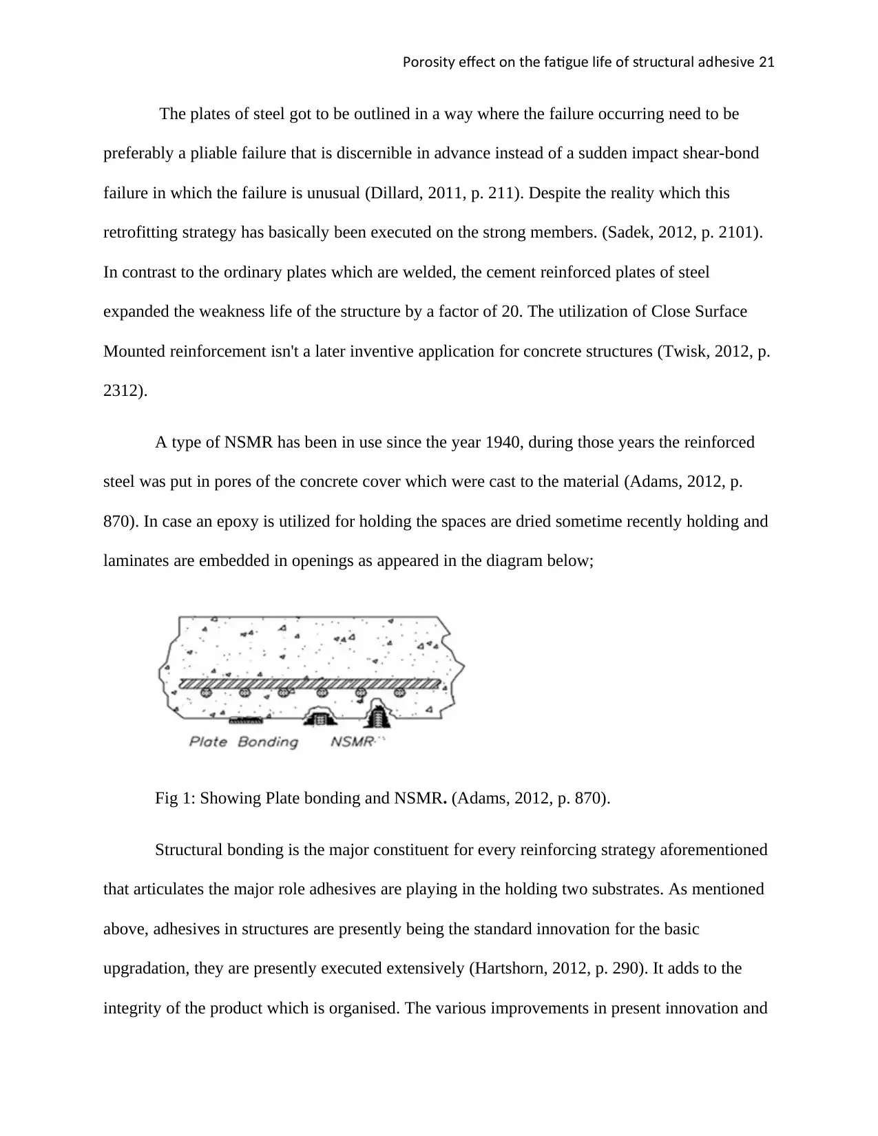
870). In case an epoxy is utilized for holding the spaces are dried sometime recently holding and
laminates are embedded in openings as appeared in the diagram below;
Fig 1: Showing Plate bonding and NSMR. (Adams, 2012, p. 870).
Structural bonding is the major constituent for every reinforcing strategy aforementioned
that articulates the major role adhesives are playing in the holding two substrates. As mentioned
above, adhesives in structures are presently being the standard innovation for the basic
upgradation, they are presently executed extensively (Hartshorn, 2012, p. 290). It adds to the
integrity of the product which is organised. The various improvements in present innovation and
The plates of steel got to be outlined in a way where the failure occurring need to be
preferably a pliable failure that is discernible in advance instead of a sudden impact shear-bond
failure in which the failure is unusual (Dillard, 2011, p. 211). Despite the reality which this
retrofitting strategy has basically been executed on the strong members. (Sadek, 2012, p. 2101).
In contrast to the ordinary plates which are welded, the cement reinforced plates of steel
expanded the weakness life of the structure by a factor of 20. The utilization of Close Surface
Mounted reinforcement isn't a later inventive application for concrete structures (Twisk, 2012, p.
2312).
A type of NSMR has been in use since the year 1940, during those years the reinforced
steel was put in pores of the concrete cover which were cast to the material (Adams, 2012, p.
870). In case an epoxy is utilized for holding the spaces are dried sometime recently holding and
laminates are embedded in openings as appeared in the diagram below;
Fig 1: Showing Plate bonding and NSMR. (Adams, 2012, p. 870).
Structural bonding is the major constituent for every reinforcing strategy aforementioned
that articulates the major role adhesives are playing in the holding two substrates. As mentioned
above, adhesives in structures are presently being the standard innovation for the basic
upgradation, they are presently executed extensively (Hartshorn, 2012, p. 290). It adds to the
integrity of the product which is organised. The various improvements in present innovation and
Poro it e ect on t e ati e li e o tr ct ral ad e i es y ff h f gu f f s u u h s v 22
adhesives of unused ones have an awesome consequence on the expanding applications of
cement in the construction industry. There are various benefits in choosing adhesives of
structures rather than the traditional techniques, for example, they have the capability to
conglomerate any assortment of material independent of their structure.
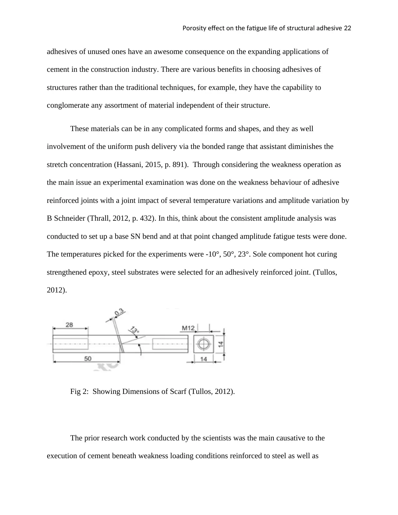
These materials can be in any complicated forms and shapes, and they as well
involvement of the uniform push delivery via the bonded range that assistant diminishes the
stretch concentration (Hassani, 2015, p. 891). Through considering the weakness operation as
the main issue an experimental examination was done on the weakness behaviour of adhesive
reinforced joints with a joint impact of several temperature variations and amplitude variation by
B Schneider (Thrall, 2012, p. 432). In this, think about the consistent amplitude analysis was
conducted to set up a base SN bend and at that point changed amplitude fatigue tests were done.
The temperatures picked for the experiments were -10°, 50°, 23°. Sole component hot curing
strengthened epoxy, steel substrates were selected for an adhesively reinforced joint. (Tullos,
2012).
Fig 2: Showing Dimensions of Scarf (Tullos, 2012).
The prior research work conducted by the scientists was the main causative to the
execution of cement beneath weakness loading conditions reinforced to steel as well as
adhesives of unused ones have an awesome consequence on the expanding applications of
cement in the construction industry. There are various benefits in choosing adhesives of
structures rather than the traditional techniques, for example, they have the capability to
conglomerate any assortment of material independent of their structure.
These materials can be in any complicated forms and shapes, and they as well
involvement of the uniform push delivery via the bonded range that assistant diminishes the
stretch concentration (Hassani, 2015, p. 891). Through considering the weakness operation as
the main issue an experimental examination was done on the weakness behaviour of adhesive
reinforced joints with a joint impact of several temperature variations and amplitude variation by
B Schneider (Thrall, 2012, p. 432). In this, think about the consistent amplitude analysis was
conducted to set up a base SN bend and at that point changed amplitude fatigue tests were done.
The temperatures picked for the experiments were -10°, 50°, 23°. Sole component hot curing
strengthened epoxy, steel substrates were selected for an adhesively reinforced joint. (Tullos,
2012).
Fig 2: Showing Dimensions of Scarf (Tullos, 2012).
The prior research work conducted by the scientists was the main causative to the
execution of cement beneath weakness loading conditions reinforced to steel as well as
Secure Best Marks with AI Grader
Need help grading? Try our AI Grader for instant feedback on your assignments.
Poro it e ect on t e ati e li e o tr ct ral ad e i es y ff h f gu f f s u u h s v 23
substrates of concrete. Investigation of pure bonding is additionally done on a bigger range of
perspectives as specified prior on the durability, cohesive properties and glass move
temperatures. (Hutchinson, 2018, p. 321). The study on fatigue performance of pure structural
adhesive beneath different frequencies, temperature and amplitude still require a better and a
stronger investigation. Hence, the present investigation is done to analyse the immaculate
auxiliary cement characteristics and their execution beneath changing testing of temperature.
Having a reason of doing the present investigation to analyse the designing characteristics
of the basic adhesives beneath lassitude loading conditions, it is vital to comprehend the motive
behind the utilization of auxiliary bonding material in arrange to reinforce the present structures
of concrete and steel as an effective strategy in later times (Brockmann, 2009, p. 1020). The
different components affecting the operation of the adhesive is additionally a vital point within
the present research. In the past section a review on the background of structural adhesives,
different applications on concrete and steel structures, past think about on cement is
comprehended (Ebnesajjad, 2012, p. 909).
Fortifying and Retrofitting of current steel structures as well as concrete structures has
come progressively in centre of centre amid the final decade. All over there are offices
anticipated for different purposes for the transportation, living, commercial offices. (John, 2012,
p. 431). All the ancient and weakened structures require support, rebuilding and fortifying
methods to make strides their basic execution. Alongside the old structures, unused structures in
which mistakes might take put within the development stage moreover have the equal necessity
of fortifying (Krul, 2013, p. 541). This report too examines the characteristics of cement and the
reason linked to their execution drop beneath hoisted temperatures. Few preparatory inactive
stacking tests were done to decide the greatest malleable push of the particular cement from
Poro it e ect on t e ati e li e o tr ct ral ad e i es y ff h f gu f f s u u h s v 24
which the overall stack and a sufficiency run of 10% to 60% of the stack are obtained. A steady
recurrence of 4Hz is kept up for all the experiments (Carpinteri, 2013, p. 321).
Testing Conducted
There are several tests which were conducted when the test was conducted, there are some
parameters which must be considered, some of those parameters include;
a) Temperature
b) Frequency
c) Amplitude
Temperature
The testing of the present research is done in two distinctive scenarios of temperature to analyse
the characteristics and execution of the cement as the temperature is additionally the main figure
which impacts the structural characteristics of cement (Cognard, 2013, p. 453). Temperature is
furthers classified as testing temperatures and curing temperature.
Curing Temperature
As specified within the past area curing at relatively lesser temperature the gain in solidness of
the example is more when contrasted to pick up in quality (Schröder, 2014, p. 321).
Poro it e ect on t e ati e li e o tr ct ral ad e i es y ff h f gu f f s u u h s v 25
Alternatively, at higher curing temperature, the gain in quality of the example is rapid and higher
when contrasted to gain in solidness. As specified within the over an area the curing temperature
picked in the present study is quickened curing temperature of 50 ̊ C for Araldite 420 for 4 hours
and 40°C for S&P Tar 220 for 4 hours (Adams, 2011, p. 1002).
Frequency
The number of cycles rehashed in a given time unit. The ideal range of frequency picked, in
theory, is about 5Hz to 3Hz. As we surpass past 5Hz the machine begins vibrating that may lead
in cracks of the armature as the frequency increments a slight sum of inner warm is produced
that may not result to express outcome (Teng, 2013, p. 1210). In order to dodge the
aforementioned fiascos, the frequency chose for testing is within the ideal range that is
about4Hz.
Amplitude
This is the height the peak should be recorded from the balance line. The amplitude basically is
between 20% and 60% of the extreme load on the structural material. Grounded on the
characteristics of the live observations as well as epoxies gotten from writing the amplitude
extend anticipated as being between 26Mpa and 22Mpa. This is often the case of immaculate
epoxy testing (Franco, 2012, p. 431). Through considering the faithful tactic the amplitude run
selected within the current thought is about is 60%. The reason behind picking 10% to 60% of
extreme stack as the sufficiency is considering a bridge condition where the section of a little car
can exchange a stack of 10% to the basic holding and the entry of overwhelming truck can
exchange a stack of 60% to the cement bond layer (Hurm, 2012, p. 432). The computer program
utilized for testing produces automatic outcomes of the test is given in excel file format for
every given cycle as seen in the diagram below;
Paraphrase This Document
Need a fresh take? Get an instant paraphrase of this document with our AI Paraphraser
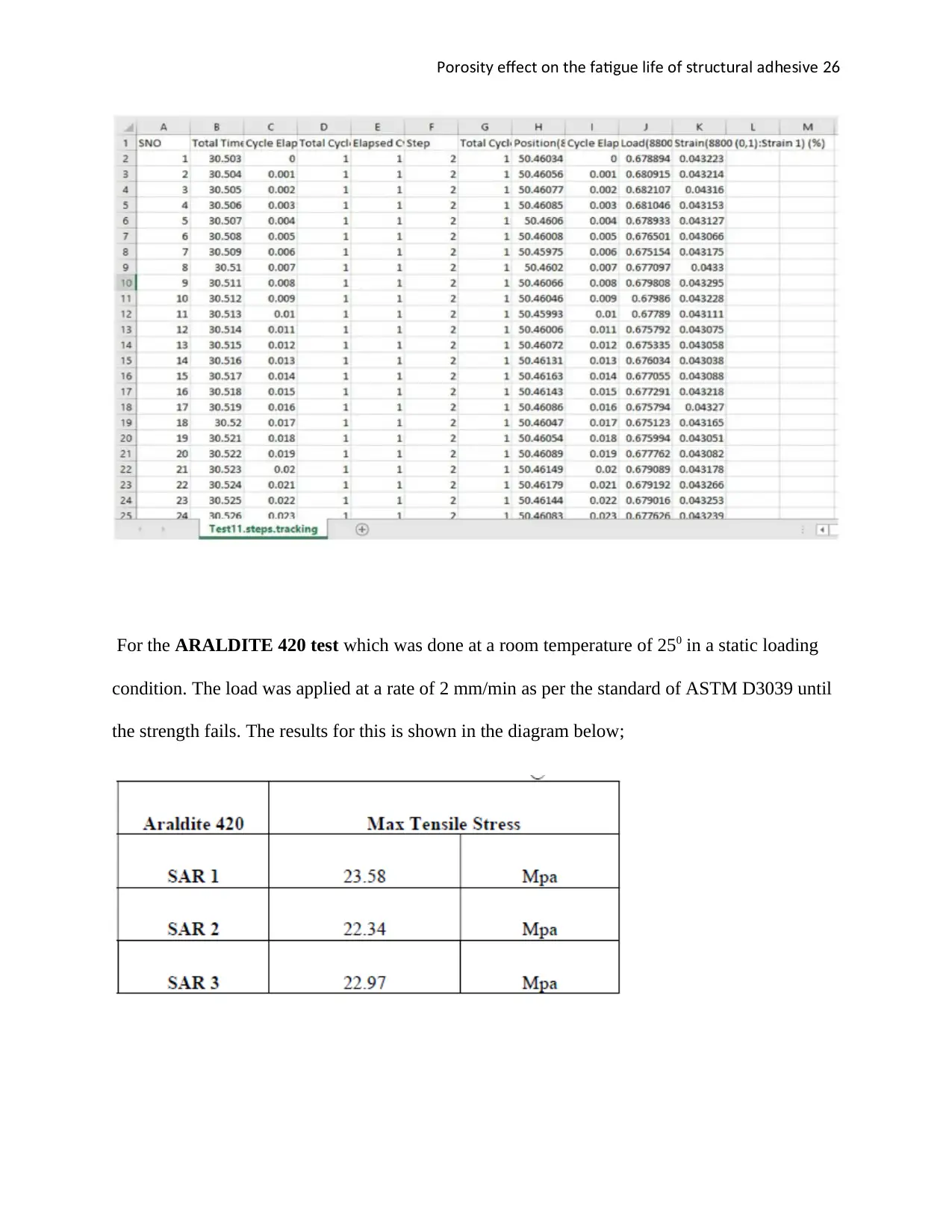
Poro it e ect on t e ati e li e o tr ct ral ad e i es y ff h f gu f f s u u h s v 26
For the ARALDITE 420 test which was done at a room temperature of 250 in a static loading
condition. The load was applied at a rate of 2 mm/min as per the standard of ASTM D3039 until
the strength fails. The results for this is shown in the diagram below;
For the ARALDITE 420 test which was done at a room temperature of 250 in a static loading
condition. The load was applied at a rate of 2 mm/min as per the standard of ASTM D3039 until
the strength fails. The results for this is shown in the diagram below;
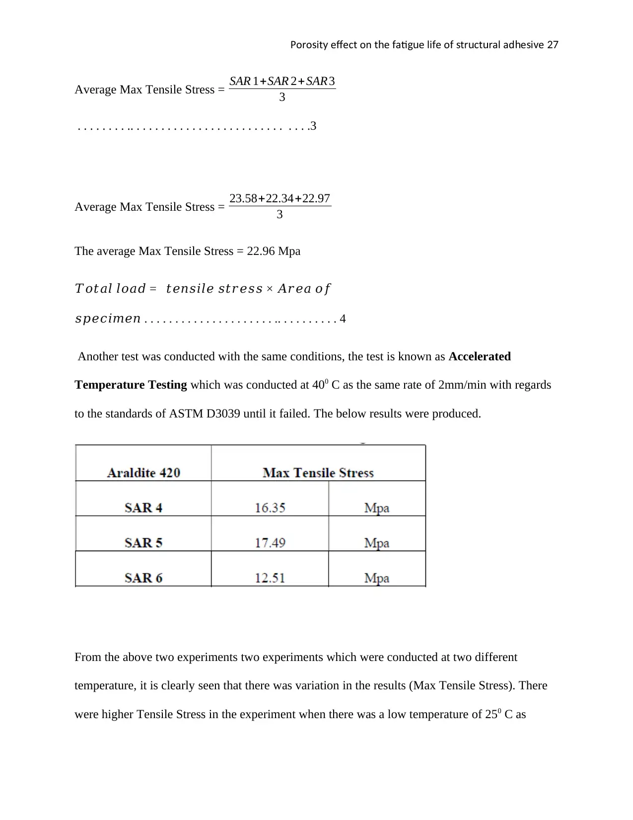
Poro it e ect on t e ati e li e o tr ct ral ad e i es y ff h f gu f f s u u h s v 27
Average Max Tensile Stress = SAR 1+SAR 2+ SAR3
3
. . . . . . . . .. . . . . . . . . . . . . . . . . . . . . . . . . . . . .3
Average Max Tensile Stress = 23.58+22.34+22.97
3
The average Max Tensile Stress = 22.96 Mpa
𝑇𝑜𝑡𝑎𝑙 𝑙𝑜𝑎𝑑 = 𝑡𝑒𝑛𝑠𝑖𝑙𝑒 𝑠𝑡𝑟𝑒𝑠𝑠 × 𝐴𝑟𝑒𝑎 𝑜𝑓
𝑠𝑝𝑒𝑐𝑖𝑚𝑒𝑛 . . . . . . . . . . . . . . . . . . . . . .. . . . . . . . . . 4
Another test was conducted with the same conditions, the test is known as Accelerated
Temperature Testing which was conducted at 400 C as the same rate of 2mm/min with regards
to the standards of ASTM D3039 until it failed. The below results were produced.
From the above two experiments two experiments which were conducted at two different
temperature, it is clearly seen that there was variation in the results (Max Tensile Stress). There
were higher Tensile Stress in the experiment when there was a low temperature of 250 C as
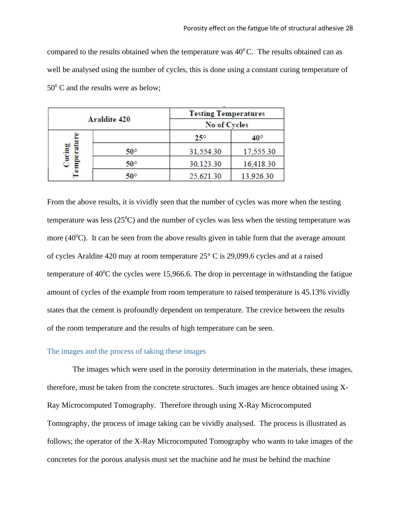
Poro it e ect on t e ati e li e o tr ct ral ad e i es y ff h f gu f f s u u h s v 28
compared to the results obtained when the temperature was 400 C. The results obtained can as
well be analysed using the number of cycles, this is done using a constant curing temperature of
500 C and the results were as below;
From the above results, it is vividly seen that the number of cycles was more when the testing
temperature was less (250C) and the number of cycles was less when the testing temperature was
more (400C). It can be seen from the above results given in table form that the average amount
of cycles Araldite 420 may at room temperature 25° C is 29,099.6 cycles and at a raised
temperature of 400C the cycles were 15,966.6. The drop in percentage in withstanding the fatigue
amount of cycles of the example from room temperature to raised temperature is 45.13% vividly
states that the cement is profoundly dependent on temperature. The crevice between the results
of the room temperature and the results of high temperature can be seen.
The images and the process of taking these images
The images which were used in the porosity determination in the materials, these images,
therefore, must be taken from the concrete structures. Such images are hence obtained using X-
Ray Microcomputed Tomography. Therefore through using X-Ray Microcomputed
Tomography, the process of image taking can be vividly analysed. The process is illustrated as
follows; the operator of the X-Ray Microcomputed Tomography who wants to take images of the
concretes for the porous analysis must set the machine and he must be behind the machine
Secure Best Marks with AI Grader
Need help grading? Try our AI Grader for instant feedback on your assignments.

Poro it e ect on t e ati e li e o tr ct ral ad e i es y ff h f gu f f s u u h s v 29
having protective clothing. The operators need to place the scanner in a distinctive table. Even
though the scanner is highly shielded a lot of care still need to be considered. The operator will
position the object /concrete structure in a correct position then the beam of electrons from the
X-ray machine is directed to the structure in question. The beams will be blocked and the image
of the concrete will be blocked by the structure thereby taking the image of it. The below further
explains what takes place during the image taking in the X-ray machine.
Principle
Since microtomography scanner provides isotropic, display, resolution of the image doesn’t
require to be conventional axial images. Instead, it’s likely for software to develop a volume by
stacking the material slice one on top of each other´s material.
Image reconstruction software
For X-Ray Microcomputed Tomography, a powerful source program is present for example
ASTRA toolbox. Basically, this is MATLAB toolbox of very high performance in the image
reconstruction for both 2 D and 3D topography. A large number of reconstruction algorithms
available for the operator may include the ART, SART, CGLS and FBT
Volume rendering
This is a technique which the operator will employ to generate and display 2 D projection of a
3D discretely data sampled. Basically, the operator requires all these in a regular pattern and
actually have an even number of pixels of the image in a steady pattern.
Image segmentation
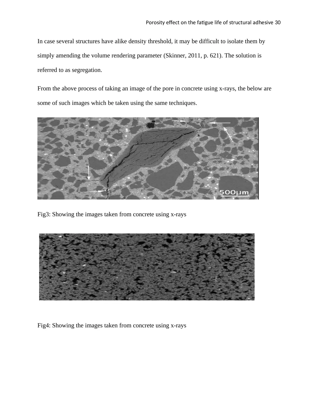
Poro it e ect on t e ati e li e o tr ct ral ad e i es y ff h f gu f f s u u h s v 30
In case several structures have alike density threshold, it may be difficult to isolate them by
simply amending the volume rendering parameter (Skinner, 2011, p. 621). The solution is
referred to as segregation.
From the above process of taking an image of the pore in concrete using x-rays, the below are
some of such images which be taken using the same techniques.
Fig3: Showing the images taken from concrete using x-rays
Fig4: Showing the images taken from concrete using x-rays

Poro it e ect on t e ati e li e o tr ct ral ad e i es y ff h f gu f f s u u h s v 31
Fig5: Showing the images taken from concrete using x-rays
Talk about the available software and why you chose a specific one
There are many software which can be employed in the analysis of the analysis for the porosity
of images. These software help engineers to get the actual porosity in any given dawn image.
Some of the common software employed includes the following;
i. Avizo 3 D Analysis software
ii. MIPAR Image Analyse
iii. Image J software
Avizo 3 D
This is one of the software which is employed in the analysis of the porosity of the image.
It is a computer program application that empowers users to perform intuitively visualization and
computation on 3D information sets. The Avizo interface is displayed on the visual
programming. Clients control information and module components, organized in an intuitive
chart representation (called Pool), or in a Tree view. Information and modules can be intelligence
Paraphrase This Document
Need a fresh take? Get an instant paraphrase of this document with our AI Paraphraser
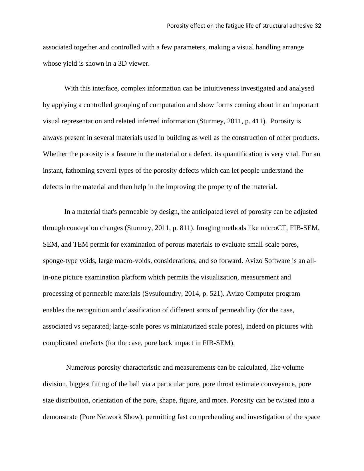
Poro it e ect on t e ati e li e o tr ct ral ad e i es y ff h f gu f f s u u h s v 32
associated together and controlled with a few parameters, making a visual handling arrange
whose yield is shown in a 3D viewer.
With this interface, complex information can be intuitiveness investigated and analysed
by applying a controlled grouping of computation and show forms coming about in an important
visual representation and related inferred information (Sturmey, 2011, p. 411). Porosity is
always present in several materials used in building as well as the construction of other products.
Whether the porosity is a feature in the material or a defect, its quantification is very vital. For an
instant, fathoming several types of the porosity defects which can let people understand the
defects in the material and then help in the improving the property of the material.
In a material that's permeable by design, the anticipated level of porosity can be adjusted
through conception changes (Sturmey, 2011, p. 811). Imaging methods like microCT, FIB-SEM,
SEM, and TEM permit for examination of porous materials to evaluate small-scale pores,
sponge-type voids, large macro-voids, considerations, and so forward. Avizo Software is an all-
in-one picture examination platform which permits the visualization, measurement and
processing of permeable materials (Svsufoundry, 2014, p. 521). Avizo Computer program
enables the recognition and classification of different sorts of permeability (for the case,
associated vs separated; large-scale pores vs miniaturized scale pores), indeed on pictures with
complicated artefacts (for the case, pore back impact in FIB-SEM).
Numerous porosity characteristic and measurements can be calculated, like volume
division, biggest fitting of the ball via a particular pore, pore throat estimate conveyance, pore
size distribution, orientation of the pore, shape, figure, and more. Porosity can be twisted into a
demonstrate (Pore Network Show), permitting fast comprehending and investigation of the space
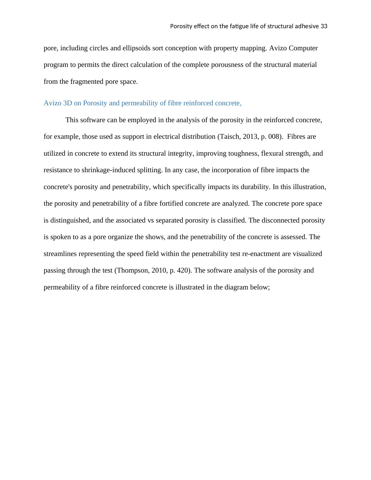
Poro it e ect on t e ati e li e o tr ct ral ad e i es y ff h f gu f f s u u h s v 33
pore, including circles and ellipsoids sort conception with property mapping. Avizo Computer
program to permits the direct calculation of the complete porousness of the structural material
from the fragmented pore space.
Avizo 3D on Porosity and permeability of fibre reinforced concrete,
This software can be employed in the analysis of the porosity in the reinforced concrete,
for example, those used as support in electrical distribution (Taisch, 2013, p. 008). Fibres are
utilized in concrete to extend its structural integrity, improving toughness, flexural strength, and
resistance to shrinkage-induced splitting. In any case, the incorporation of fibre impacts the
concrete's porosity and penetrability, which specifically impacts its durability. In this illustration,
the porosity and penetrability of a fibre fortified concrete are analyzed. The concrete pore space
is distinguished, and the associated vs separated porosity is classified. The disconnected porosity
is spoken to as a pore organize the shows, and the penetrability of the concrete is assessed. The
streamlines representing the speed field within the penetrability test re-enactment are visualized
passing through the test (Thompson, 2010, p. 420). The software analysis of the porosity and
permeability of a fibre reinforced concrete is illustrated in the diagram below;
Poro it e ect on t e ati e li e o tr ct ral ad e i es y ff h f gu f f s u u h s v 34
Fig 6: Showing the software analysis diagram of Avizo on Porosity and permeability of fibre
reinforced concrete
MIPAR Image
This is another software employed in the analysis of the image porosity in the materials
MIPAR in full is Material Image Processing and Automated Reconstruction. This type of
software can be employed in the analysis of both 3D and 2D image. Almost all analysis
endeavours will begin in the, to begin with use which is the Picture Processor. This powerful, yet
accessible environment permits operators to create an order of steps of processing referred to as a
recipe (aluminum, 2010, p. 650). The particular parameters and steps instituting a recipe that will
vary grounded on the user’s aim, but the extreme objective of most formulas is the same: to
portion raw concentrated into a group of features. An operator’s process choices are measured in
real-time, allowing consequent parameter editing and also process evacuation and insertion.
This use functions to consequently use the recipe to an arrangement of pictures, either
haphazardly collected for 2D examination, or to include a 3D stack. For 3D work, extra stages
Secure Best Marks with AI Grader
Need help grading? Try our AI Grader for instant feedback on your assignments.
Poro it e ect on t e ati e li e o tr ct ral ad e i es y ff h f gu f f s u u h s v 35
like tilt-correction, picture arrangement, and volume recreations may all be conducted, allowing
a sole liquid workflow. In case a bunch prepare was done for 2D examination may be opened
straightforwardly within the Prepared Picture Editor. This environment licenses quickened
survey of a recipe’s division quality overall prepared pictures. On the off chance that vital,
manual division altering is accessible, too in exceptionally productive shape.
At long last, in the event that either worldwide or highlight estimations are wanted, they
can be effectively yielded from all handled pictures in excel format. In case a batch process
delivered either a picture stack or reproduced volume, the 3D Toolkit gives a host of instruments
for connection with measuring, editing, visualizing this info. In case a stack or recreation was
done with arrangements, the measurable slice-to-slice interpretations can be seen as scatter plots.
Editing of the picture stack or recreation can be done interactively. In some scenario, a direct 3D
division can be predominant to the conservative slice-by-slice division. In that matter, every pre-
processing and division would be done in the 3D Toolkit specifically on the adjusted 3 D data. In
the event that slice-by-slice division was favoured, the 3D Toolkit can still permit numerous
reduction of noise and include division apparatuses – all directly performed on the 3D division.
The flowing are some of the images taken from the MIPAR image software;
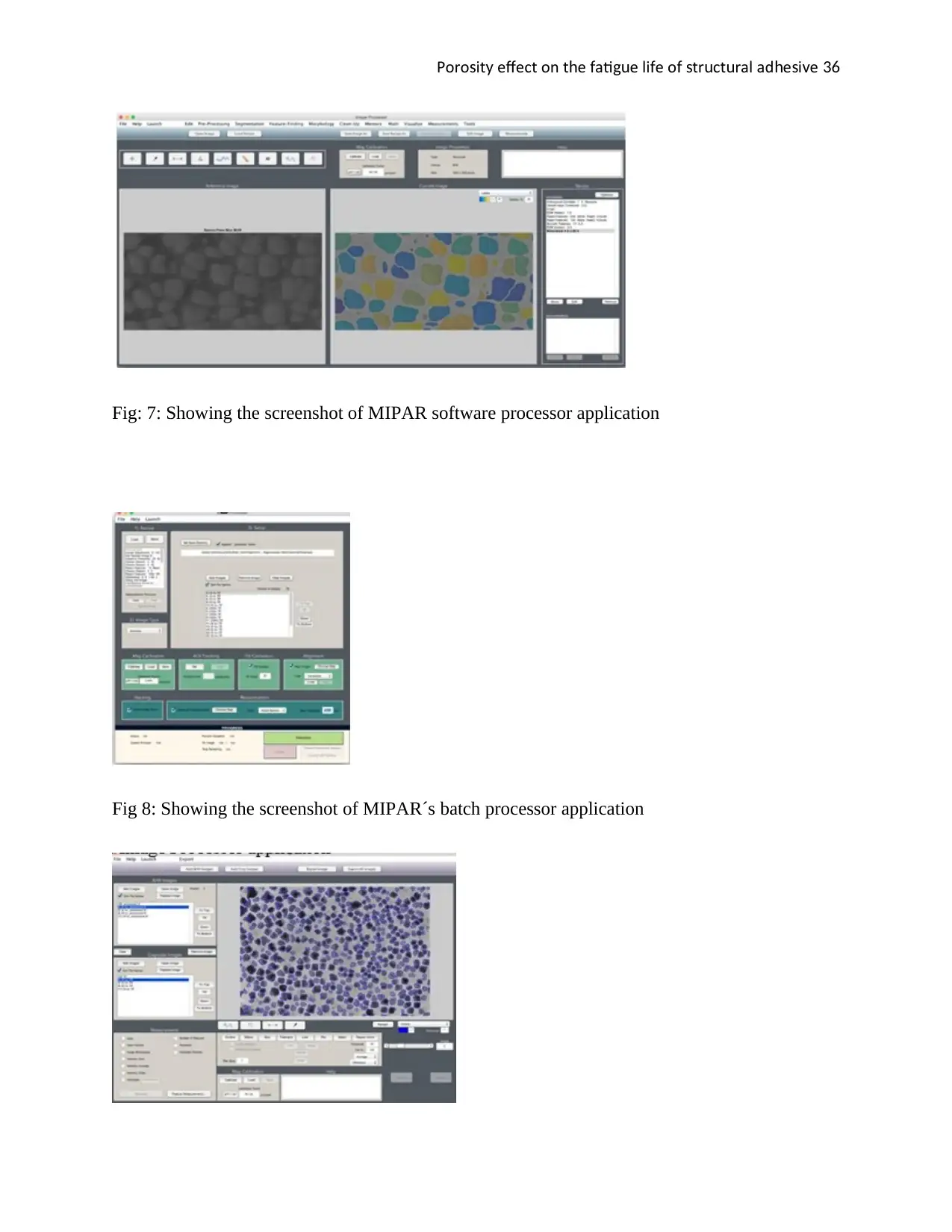
Poro it e ect on t e ati e li e o tr ct ral ad e i es y ff h f gu f f s u u h s v 36
Fig: 7: Showing the screenshot of MIPAR software processor application
Fig 8: Showing the screenshot of MIPAR´s batch processor application
Fig: 7: Showing the screenshot of MIPAR software processor application
Fig 8: Showing the screenshot of MIPAR´s batch processor application
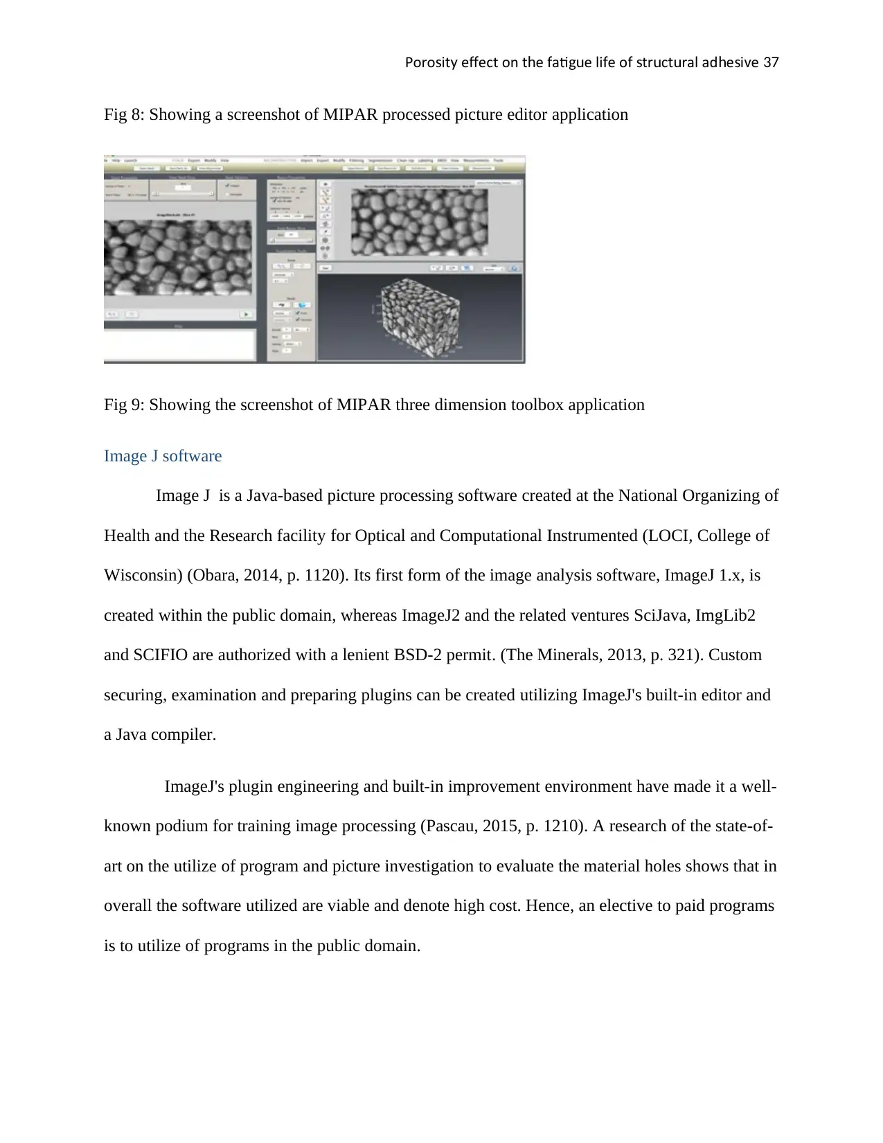
Poro it e ect on t e ati e li e o tr ct ral ad e i es y ff h f gu f f s u u h s v 37
Fig 8: Showing a screenshot of MIPAR processed picture editor application
Fig 9: Showing the screenshot of MIPAR three dimension toolbox application
Image J software
Image J is a Java-based picture processing software created at the National Organizing of
Health and the Research facility for Optical and Computational Instrumented (LOCI, College of
Wisconsin) (Obara, 2014, p. 1120). Its first form of the image analysis software, ImageJ 1.x, is
created within the public domain, whereas ImageJ2 and the related ventures SciJava, ImgLib2
and SCIFIO are authorized with a lenient BSD-2 permit. (The Minerals, 2013, p. 321). Custom
securing, examination and preparing plugins can be created utilizing ImageJ's built-in editor and
a Java compiler.
ImageJ's plugin engineering and built-in improvement environment have made it a well-
known podium for training image processing (Pascau, 2015, p. 1210). A research of the state-of-
art on the utilize of program and picture investigation to evaluate the material holes shows that in
overall the software utilized are viable and denote high cost. Hence, an elective to paid programs
is to utilize of programs in the public domain.
Paraphrase This Document
Need a fresh take? Get an instant paraphrase of this document with our AI Paraphraser
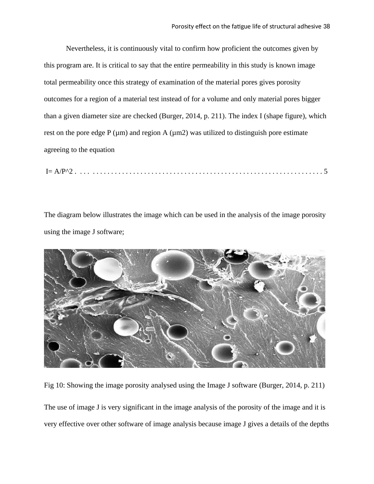
Poro it e ect on t e ati e li e o tr ct ral ad e i es y ff h f gu f f s u u h s v 38
Nevertheless, it is continuously vital to confirm how proficient the outcomes given by
this program are. It is critical to say that the entire permeability in this study is known image
total permeability once this strategy of examination of the material pores gives porosity
outcomes for a region of a material test instead of for a volume and only material pores bigger
than a given diameter size are checked (Burger, 2014, p. 211). The index I (shape figure), which
rest on the pore edge P (μm) and region A (μm2) was utilized to distinguish pore estimate
agreeing to the equation
I= A/P^2 . . . . . . . . . . . . . . . . . . . . . . . . . . . . . . . . . . . . . . . . . . . . . . . . . . . . . . . . . . . . . . . . . . . 5
The diagram below illustrates the image which can be used in the analysis of the image porosity
using the image J software;
Fig 10: Showing the image porosity analysed using the Image J software (Burger, 2014, p. 211)
The use of image J is very significant in the image analysis of the porosity of the image and it is
very effective over other software of image analysis because image J gives a details of the depths

Poro it e ect on t e ati e li e o tr ct ral ad e i es y ff h f gu f f s u u h s v 39
of the porous given in the image given in both 2 D and 3 D. Another advantage of image J is
that image J is and free at the same time it is a user-friendly. Therefore the image J was
employed in the analysis of the images to know the porosity of every hole given in the images,
The below are some of the basics procedure which is employed in the analysis of porosity of the
image using image J software;
1. Opening the image and cropping it to eliminate the unnecessary parts.
2. The images were saved in the format that is readable by image and for this case, we
used .png and tiff.
3. We introduced scaled the image using the scale that was given for each image.
4. The image type was set to be 32bit and the adjustment for the threshold was done to a
reasonable level. The coloured area in red represent the pores within that region.
5. On analysis, we chose the set measurement and selected the area, percentage area and
ferret for analysis. Then we chose particle analysis, which calculates the results
automatically on pressing okay.
The percentage area represents the porosity for the images, which has been highlighted in yellow
as shown in the table below. The other results for the analysis can be found in the folder for all
the images, which was done separately.

Poro it e ect on t e ati e li e o tr ct ral ad e i es y ff h f gu f f s u u h s v 40
Talk about the process of measuring the porosity in details
The process of measuring porosity in the structure was done through one of the available
software known as image J. The discussed below procedure is always employed to help in
obtaining the accurate porosity of an image given in either 2 D or 3 D diagram (Broeke, 2014, p.
431).
First step: Open file
This is the first step of the porosity calculation, in this step, the file containing the correct images
whose porosity are to be determined should be opened.
Second step: Cutting the image
It is important in this step to remove the SEM info bar in the bottommost part of the image, this
is done using rectangular which is composed of just SEM images then use the menu in the
software known as crop (click on the tab crop) (Maceri, 2013, p. 987).
Step three: Conversion of image format to either tiff or BMP format.
In most the images will be in jpg format, therefore this format must be converted to either tiff or
BMP format. To convert the jpg to tiff, there are some simple steps which are employed in the
process, such procedure includes the following;
- Install TIFF image printer on the computer and it should give new virtual printer in the
new printer folder.
- Open the JPG image in the favourite picture viewer and choose the print from the toolbar
and then select the print option.
Secure Best Marks with AI Grader
Need help grading? Try our AI Grader for instant feedback on your assignments.
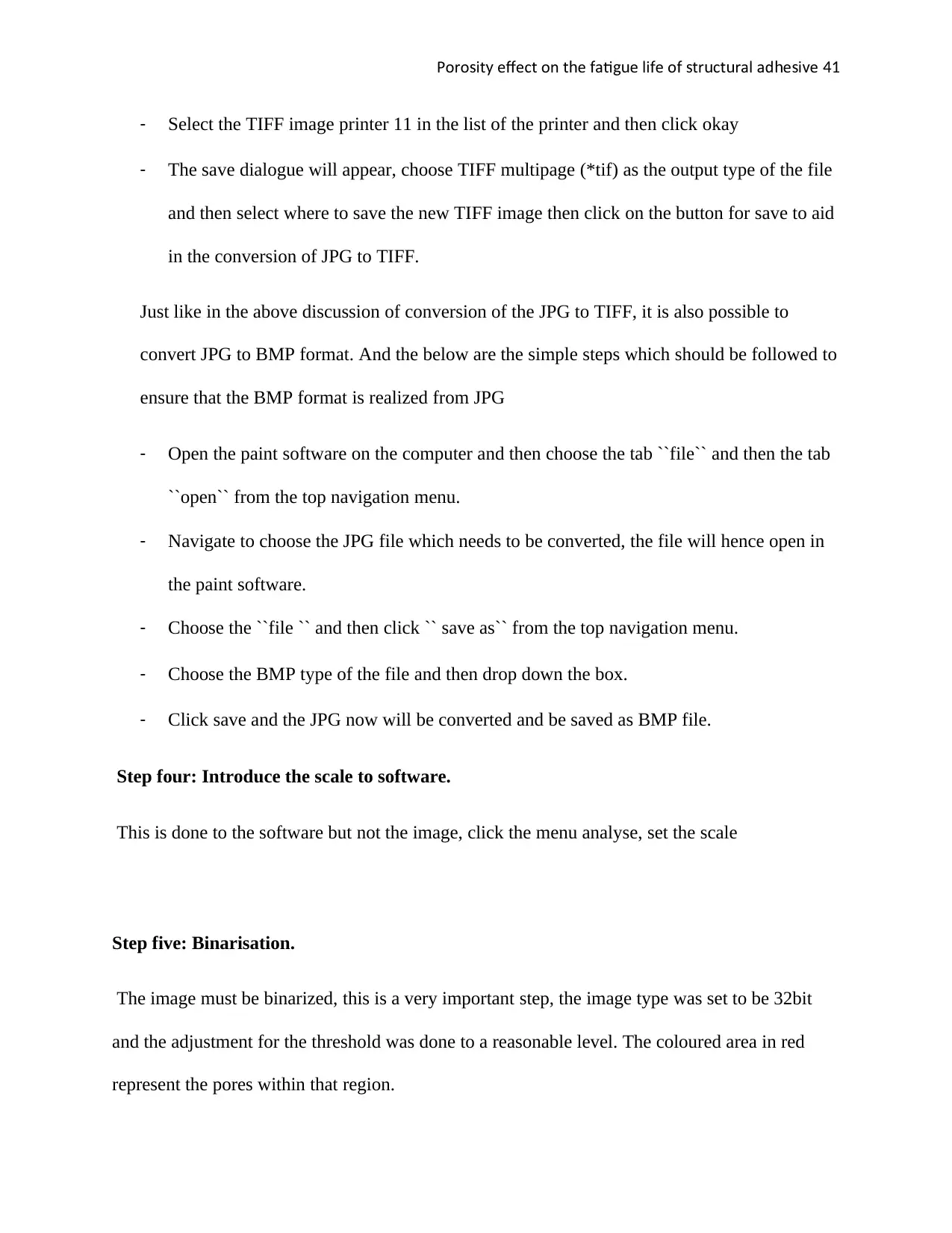
Poro it e ect on t e ati e li e o tr ct ral ad e i es y ff h f gu f f s u u h s v 41
- Select the TIFF image printer 11 in the list of the printer and then click okay
- The save dialogue will appear, choose TIFF multipage (*tif) as the output type of the file
and then select where to save the new TIFF image then click on the button for save to aid
in the conversion of JPG to TIFF.
Just like in the above discussion of conversion of the JPG to TIFF, it is also possible to
convert JPG to BMP format. And the below are the simple steps which should be followed to
ensure that the BMP format is realized from JPG
- Open the paint software on the computer and then choose the tab ``file`` and then the tab
``open`` from the top navigation menu.
- Navigate to choose the JPG file which needs to be converted, the file will hence open in
the paint software.
- Choose the ``file `` and then click `` save as`` from the top navigation menu.
- Choose the BMP type of the file and then drop down the box.
- Click save and the JPG now will be converted and be saved as BMP file.
Step four: Introduce the scale to software.
This is done to the software but not the image, click the menu analyse, set the scale
Step five: Binarisation.
The image must be binarized, this is a very important step, the image type was set to be 32bit
and the adjustment for the threshold was done to a reasonable level. The coloured area in red
represent the pores within that region.
Poro it e ect on t e ati e li e o tr ct ral ad e i es y ff h f gu f f s u u h s v 42
Step six: Use the menu analyse
After a perfect thresholding, employ the use of the analyse menu and then click on the measure
after that a new tab will pop. At this point, one needs to fathom the Feret´s pores diameter. Click
on the tab `` results`` in the new tab which popped after that click the tab distribution and a new
window will pop again then choose FERET area or diameter depending on the desires of an
individual.
Step seven: Final distribution results
This is the last part in the obtaining the porosity of the images given in either 2D or 3 D. At this
point a new window will pop up again and this window will contain pore size distribution of the
images and that is the porosity determined using this efficacy software image J.
Porosity and Permeability tests
Porosity tests in Hardened Concrete
The porosity in the reinforced concrete, as well as plain concrete structure, is a vital
characteristic that determines to a large extent their structural properties (Rose, 2015, p. 1012). A
high porosity is strongly detrimental to the strength of concrete permeability specifically if the
pores are the bigger diameter. To assess the porosity of the reinforced concrete as well as ASTM
C 642 testing processes, bulk saturated the dry surface of reinforced concrete (Scott, 2012, p.
212). The steel fibre strengthen concrete and plain concrete was evaluated using the below
equation
T.V = 1- y 1
y ×100 . . . . . . . . . . . . . . . . . . . . . . . . . . . . . . . . . . . . . . . . . . . . . . . . . . . . . . . . . . . . 6
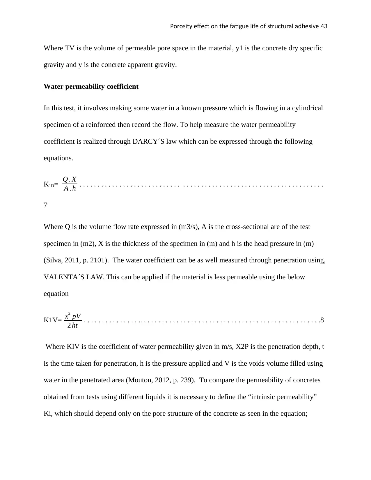
Poro it e ect on t e ati e li e o tr ct ral ad e i es y ff h f gu f f s u u h s v 43
Where TV is the volume of permeable pore space in the material, y1 is the concrete dry specific
gravity and y is the concrete apparent gravity.
Water permeability coefficient
In this test, it involves making some water in a known pressure which is flowing in a cylindrical
specimen of a reinforced then record the flow. To help measure the water permeability
coefficient is realized through DARCY´S law which can be expressed through the following
equations.
K1D= Q. X
A .h . . . . . . . . . . . . . . . . . . . . . . . . . . . . . . . . . . . . . . . . . . . . . . . . . . . . . . . . . . . . . . . . . . .
7
Where Q is the volume flow rate expressed in (m3/s), A is the cross-sectional are of the test
specimen in (m2), X is the thickness of the specimen in (m) and h is the head pressure in (m)
(Silva, 2011, p. 2101). The water coefficient can be as well measured through penetration using,
VALENTA´S LAW. This can be applied if the material is less permeable using the below
equation
K1V= x2 pV
2 ht . . . . . . . . . . . . . . . .. . . . . . . . . . . . . . . . . . . . . . . . . . . . . . . . . . . . . . . . . . . . . . . . . .8
Where KIV is the coefficient of water permeability given in m/s, X2P is the penetration depth, t
is the time taken for penetration, h is the pressure applied and V is the voids volume filled using
water in the penetrated area (Mouton, 2012, p. 239). To compare the permeability of concretes
obtained from tests using different liquids it is necessary to define the “intrinsic permeability”
Ki, which should depend only on the pore structure of the concrete as seen in the equation;
Paraphrase This Document
Need a fresh take? Get an instant paraphrase of this document with our AI Paraphraser
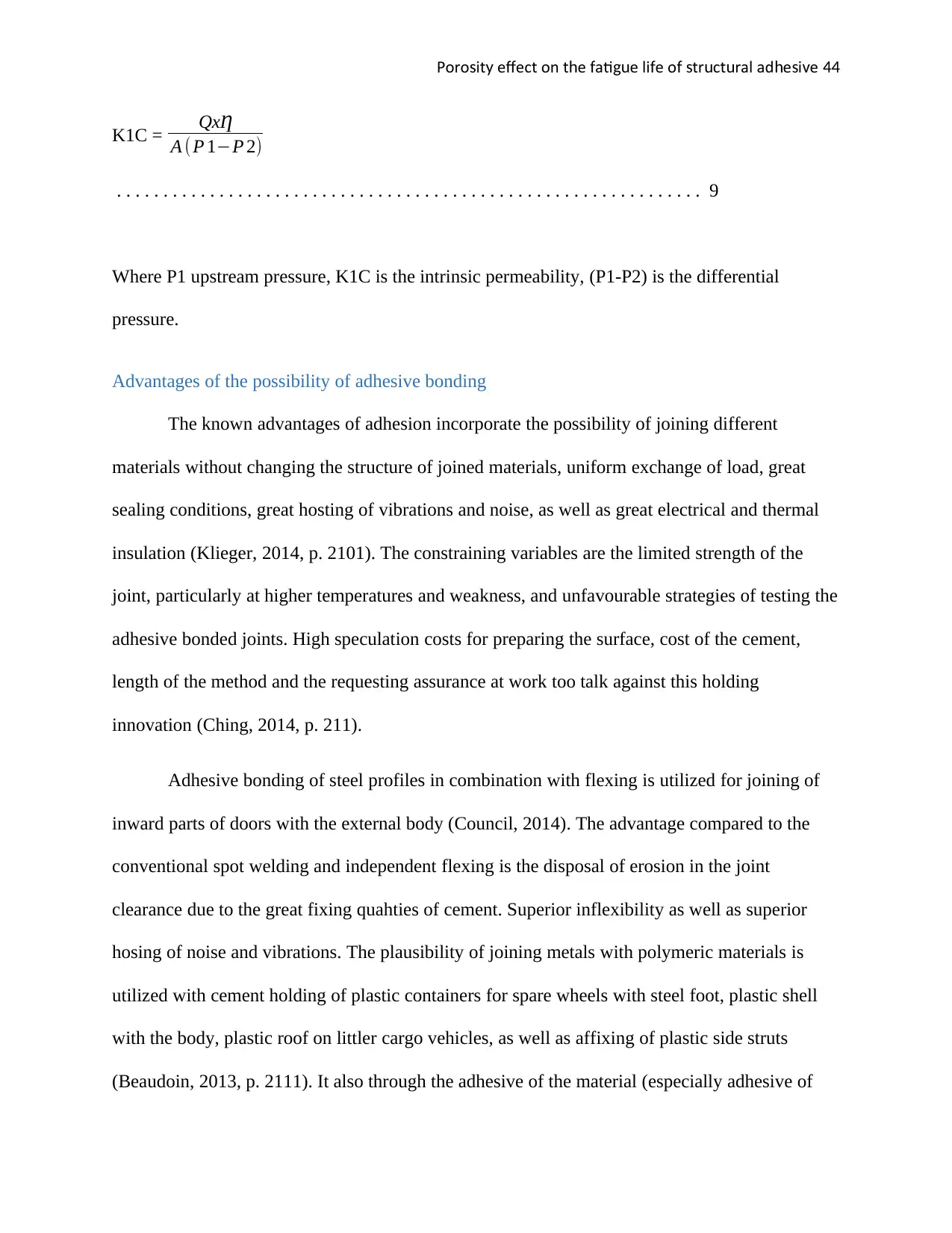
Poro it e ect on t e ati e li e o tr ct ral ad e i es y ff h f gu f f s u u h s v 44
K1C = QxȠ
A ( P 1−P 2)
. . . . . . . . . . . . . . . . . . . . . . . . . . . . . . . . . . . . . . . . . . . . . . . . . . . . . . . . . . . . . . . 9
Where P1 upstream pressure, K1C is the intrinsic permeability, (P1-P2) is the differential
pressure.
Advantages of the possibility of adhesive bonding
The known advantages of adhesion incorporate the possibility of joining different
materials without changing the structure of joined materials, uniform exchange of load, great
sealing conditions, great hosting of vibrations and noise, as well as great electrical and thermal
insulation (Klieger, 2014, p. 2101). The constraining variables are the limited strength of the
joint, particularly at higher temperatures and weakness, and unfavourable strategies of testing the
adhesive bonded joints. High speculation costs for preparing the surface, cost of the cement,
length of the method and the requesting assurance at work too talk against this holding
innovation (Ching, 2014, p. 211).
Adhesive bonding of steel profiles in combination with flexing is utilized for joining of
inward parts of doors with the external body (Council, 2014). The advantage compared to the
conventional spot welding and independent flexing is the disposal of erosion in the joint
clearance due to the great fixing quahties of cement. Superior inflexibility as well as superior
hosing of noise and vibrations. The plausibility of joining metals with polymeric materials is
utilized with cement holding of plastic containers for spare wheels with steel foot, plastic shell
with the body, plastic roof on littler cargo vehicles, as well as affixing of plastic side struts
(Beaudoin, 2013, p. 2111). It also through the adhesive of the material (especially adhesive of
Poro it e ect on t e ati e li e o tr ct ral ad e i es y ff h f gu f f s u u h s v 45
the cement) that several joints can be made in building structures used in the building bridges
and houses in the building constructions industries.
Result
Conclusion
In conclusion, Structural adhesives are characterized in consideration to their chemistries,
therefore, they possess abilities to overlap shear strengths that approximately exceeds several psi
when exposed in metal bonding under room temperature testing. Notwithstanding the existence
of hybrids, structural adhesives majorly constitute acrylic, epoxy and urethane as discussed
above. From the research done out by researchers, it was understood that structural adhesives
are commonly employed in applications which requires durability as a major factor. Structural
adhesives have vital advantages compared to mechanical and fusion fastening leading to its wide
application.
Nevertheless, structural adhesives aides in reducing the average weight of the
components while increasing its durability and at the same time providing a significantly
increased or larger latitude of design. The above-mentioned benefits associated with structural
adhesives are achieved with limited machine requirements which generally less costly compared
to utilisation of their Media of fixation. Furthermore, structural adhesives are also supplemented
by advantages relating to aesthetics involving lines which are of high cleanliness and lacks nails
that protrude, marks of welds and rivets.
Several varieties of substrates were got from acrylic adhesives which include the hard to
bond plastics together with oily metals in general. The high strength bonding is obtained minus
the preparation of the surface required for the epoxies and urethanes. Bead on bed adhesives is

Poro it e ect on t e ati e li e o tr ct ral ad e i es y ff h f gu f f s u u h s v 46
generally two-part products of acrylic where a single element is applied to a single substrate. The
duo is then made to combine hence finalising the elimination of mixing.
Urethane adhesives are less costly adhesives though possess a higher impact resistant two-part
products while enhancing faster curing up to an elastic band when utilised in applications that
require non-similar materials. Most of the structural adhesives are usually in possession of
solvents except products of urethane. The calculation of the porosity of the images given was
done through one of the several image software known as image J software. This image is simple
to use as early stated and it also gives a clear. The software gave the distribution of the porosity
in a very clear way of the given images.
Secure Best Marks with AI Grader
Need help grading? Try our AI Grader for instant feedback on your assignments.
Poro it e ect on t e ati e li e o tr ct ral ad e i es y ff h f gu f f s u u h s v 47
Bibliography
Adams, J., 2015. Adhesive Bonding: Science, Technology, and Applications. 4th ed. Beijing:
Taylor & Francis.
Adams, R. D., 2011. Handbook of Adhesion Technology. 5th ed. Florida: Springer Science &
Business Media.
Adams, R. D., 2012. Structural Adhesive Joints in Engineering. 1st ed. London: Springer
Science & Business Media.
Allen, W., 2016. Adhesion of structural material. 5th ed. Cardiff : Springer Science & Business
Media.
Alton, D., 2012. Building Bridges. Paris: Lion Books.
aluminum, A., 2010. Modern Railroads and Bridges. Chicago: Agency aluminum.
Amstock, J., 2011. Handbook of Adhesives and Sealants in Construction. 3rd ed. London:
McGraw Hill Professional.
Association, C. a. C., 2013. Technical Report. Paris: The Association,.
Banks, I., 2015. The Bridge. New York: Little, Brown Book.
Beaudoin, J. J., 2013. Handbook of Thermal Analysis of Construction Materials. 1st ed. Stoke:
William Andrew.
Poro it e ect on t e ati e li e o tr ct ral ad e i es y ff h f gu f f s u u h s v 48
Bridge, C., 2013. Sea-Power. Chicago: Cambridge University Press.
Bridge, I. A. o., 2014. Ironworker. California: International Association of Bridge.
Brockmann, W., 2009. Adhesive Bonding: Materials, Applications and Technology. 4th ed.
Stoke: John Wiley & Sons.
Broeke, J., 2014. Image Processing with ImageJ. 1st ed. Kumamotto: Packt Publishing.
Burger, W., 2014. Digital Image Processing: An Algorithmic Introduction Using Java. 3rd ed.
Hull: Springer.
Carpinteri, A., 2013. Advanced Technology for Design and Fabrication of Composite Materials
and Structures: Applications to the Automotive, Marine, Aerospace and Construction Industry.
3rd ed. Amstredam: Springer Science & Business Media.
Centre, N. M. I., 2014. Maritime Information Review. Perth: Netherlands Maritime Information
Centre.
Ching, F., 2014. Building Construction Illustrated. 1st ed. Florida: John Wiley & Sons.
Cognard, P., 2013. Handbook of Adhesives and Sealants: Basic Concepts and High Tech
Bonding. 4th ed. Chicago: Elsevier.
Cook, P., 2014. Concrete sea structures. Michigan: Fédération internationale de la précontrainte.
Council, N. R., 2014. Adhesives in Building: Lamination of Structural Timber Beams; Bonding
of Cementitious Materials; Bonding of Gypsum Drywall Construction. 4th ed. Florida: National
Academies.
Poro it e ect on t e ati e li e o tr ct ral ad e i es y ff h f gu f f s u u h s v 49
Dayaratnam, P., 2014. International Conference on Suspension, Cable Supported, and Cable
Stayed Bridges. Toledo: Universities Press.
Dillard, D., 2011. Advances in Structural Adhesive Bonding. 1st ed. Hull: Elsevier Science.
Dinar, A., 2016. Bridges Over Water. Paris: World Scientific.
Duan, L., 2011. Bridge Engineering: Construction and Maintenance. Michigan: CRC Press.
Duan, L., 2016. Handbook of International Bridge Engineering. New York: CRC Press.
Ebnesajjad, S., 2012. Handbook of Adhesives and Surface Preparation: Technology,
Applications and Manufacturing. 2nd ed. Chicago: William Andrew.
Erskine, L., 2010. Civil Engineering and Public Works Review,. Michigan: the University of
Michigan.
Franco, J., 2012. Approaches in Civil Engineering. 1st ed. Stoke: Springer Science & Business
Media.
Frank, P., 2014. Manufacturing planning and control. Perth: Elsevier.
Geiger, B., 2017. Bridges. Toledo: Benchmark Education Company.
Gerwick, B., 2014. Construction of Prestressed Concrete Structures. Michigan: John Wiley &
Sons.
Gerwick, C., 2013. Construction of Marine and Offshore Structures. Paris: CRC Press.
Gerwick, C., 2014. Construction of Marine and Offshore Structures. New York: CRC Press.
Hamed, K., 2016. Flood Frequency Analysis. Colorado: CRC Press.
Paraphrase This Document
Need a fresh take? Get an instant paraphrase of this document with our AI Paraphraser
Poro it e ect on t e ati e li e o tr ct ral ad e i es y ff h f gu f f s u u h s v 50
Hardyman, R., 2016. Bridges. Melbourne: The Rosen Publishing Group.
Harinder, S., 2010. Strategic Decision Making in Modern Manufacturing. Colorado: Springer
Science & Business Media.
Hartshorn, S., 2012. Structural Adhesives: Chemistry and Technology. 1st ed. Florida: Springer
Science & Business Media.
Hassani, M. M., 2015. Adhesive Bonding of Structural Hardwood Elements. 3rd ed. Hawaii:
CRC.
House, D., 2013. Cargo Work. Toledo: Routledge.
Hurm, J., 2012. Adhesive bonding in concrete. 3rd ed. Hull: CRC.
Hutchinson, M., 2018. Adhesives in Civil Engineering. 4th ed. Hull: Cambridge University Press.
Institution, T., 2013. Journal of the Institution of Engineers. Michigan: The Institution.
John, R., 2012. Adhesives in Civil Engineering materials. 1st ed. Hawaii: Cambridge University
Press.
Joseph, H., 2013. Handbook of Environmental Fluid Dynamics. Colorado: CRC Press.
Klieger, P., 2014. Significance of Tests and Properties of Concrete and Concrete-making
Materials. 4th ed. Hull: ASTM International.
Köp, B., 2010. Cooperative Design of Manufacturing Systems in SMEs. Toledo: GITO mbH
Verlag.
Krul, D., 2013. Materials for Sustainable Civil Engineering. 3rd ed. Hull: John Wiley & Sons.
Poro it e ect on t e ati e li e o tr ct ral ad e i es y ff h f gu f f s u u h s v 51
Leeming, H., 2014. Strengthening of Reinforced Concrete Structures: Using Externally-Bonded
Frp Composites in Structural and Civil Engineering. 3rd ed. Chicago: Elsevier.
Leonard, W., 2013. Bay's Signature Bridge and the Ma. Melbourne: University Press of Florida.
Lewis, M., 2014. Causal Factors that Influence Turnover Intent in a Manufacturing
Organisation. New York: University of Pretoria.
Maceri, F., 2013. Novel Approaches in Civil Engineering. 2nd ed. Hull: Springer Science &
Business Media.
Meissner, S., 2017. A Bridge Across the Ocean. Melbourne: Berkley.
Merli, G., 2014. Total manufacturing management: production organization. California:
Productivity Press.
Michigan, t. U. o., 2010. The Surveyor and Municipal and County Enginee. Michigan: the
University of Michigan.
Mouton, Y., 2012. Organic Materials for Sustainable Civil Engineering. 2nd ed. Hawaii: CRC.
Obara, Y., 2014. Xray CT for Geomaterials: Soils, Concrete, Rocks International Workshop on
Xray CT for Geomaterials, Kumamoto, Japan. 1st ed. Hawaii: CRC Press.
O'Hagan, T., 2010. Advances in Manufacturing Technology. Perth: John Wiley & Sons.
Pal, M. K., 2011. Productivity In The Organised Manufacturing Sector. Mumbai: Concept
Publishing Company.
Pascau, J., 2015. Image Processing with ImageJ. 3rd ed. Sydney: Packt Publishing.
Pesutich, J., 2017. Freezing Bridges Under Burning Skies. Toledo: AuthorHouse.
Poro it e ect on t e ati e li e o tr ct ral ad e i es y ff h f gu f f s u u h s v 52
Publishers, M. N., 2011. International Organizations and the Law of the Sea. Sidney: Martinus
Nijhoff Publishers.
Publishing, E. G., 2013. Managing innovative manufacturing. Toledo: Emerald Group
Publishing.
Rausand, M., 2013. Risk Assessment. New York: John Wiley & Sons.
Robert, H., 2011. Dynamic Manufacturing. Michigan: Simon and Schuster.
Rose, K., 2015. Adhesives in Civil Engineering. 4th ed. Florida: Cambridge University Press.
Sadek, J., 2012. Industrial Applications of Adhesive Bonding. 3rd ed. Amsterdam: Springer
Science & Business Media.
Schröder, B., 2014. Adhesive Bonding: Materials, Applications and Technology. 3rd ed. Hull:
John Wiley & Sons.
Scott, J., 2012. Dictionary Of Civil Engineering. 3rd ed. Florida: Springer Science & Business
Media.
Shroder, T., 2011. Fire on the Horizon: The Untold Story of the Gulf Oil Disaster. Perth:
HarperCollins.
Silva, L., 2011. Handbook of Adhesion Technology. 2nd ed. Florida: Springer Science &
Business Media.
Sinopoli, A., 2015. Arch Bridges. Michigan: CRC Press.
Skinner, S., 2011. Hydraulic Fluid Power. Perth: Lulu.com.
Sturmey, K., 2011. Greek Sea Bridges. Perth: Photohorus/Photography Circle publishing.
Secure Best Marks with AI Grader
Need help grading? Try our AI Grader for instant feedback on your assignments.
Poro it e ect on t e ati e li e o tr ct ral ad e i es y ff h f gu f f s u u h s v 53
Taisch, M., 2013. Advanced Manufacturing.. Michigan: CRC Press.
Teng, J.-G., 2013. FRP Composites in Civil Engineering: Proceedings of the International
Conference on FRP Composites in Civil Engineering. 2nd ed. Sydney: Taylor & Francis.
The Minerals, M. &. M. S., 2013. TMS 2014 143rd Annual Meeting & Exhibition, Annual
Meeting Supplemental Proceedings. 3rd ed. Hawaii: CRC.
Thompson, G., 2010. Bridges. Colorado: Benchmark Education Company.
Thrall, 2012. Adhesive Bonding of Aluminum Alloys. 4th ed. Chicago: CRC Press.
Tullos, T., 2012. Handbook of Adhesive Bonded Structural Repair. 3rd ed. Hawaii: Noyes
Publications.
Twisk, a. V., 2012. Surface Preparation Techniques for Adhesive Bonding. 3rd ed. Manchester:
William Andrew.
University, C., 2010. Surveyor. Melbourne: Cornell University.
University, N., 2010. Alaska Railroad Corporation Construction and Operation of a Rail Line
Between North Pole and Delta Junction. Toledo: Northwestern University.
University, N., 2010. Construction Into the Powder River Basin. Colorado: Northwestern
University.
Yue, Q., 2014. Advances in FRP Composites in Civil Engineering: Proceedings of the 5th
International Conference on FRP Composites in Civil Engineering. 3rd ed. Beijing: Springer
Science & Business Media.

Poro it e ect on t e ati e li e o tr ct ral ad e i es y ff h f gu f f s u u h s v 54
1 out of 54
Related Documents

Your All-in-One AI-Powered Toolkit for Academic Success.
+13062052269
info@desklib.com
Available 24*7 on WhatsApp / Email
![[object Object]](/_next/static/media/star-bottom.7253800d.svg)
Unlock your academic potential
© 2024 | Zucol Services PVT LTD | All rights reserved.