Design and Analysis of IEEE 33-Bus System Power Distribution Network
VerifiedAdded on 2023/06/05
|10
|662
|169
Project
AI Summary
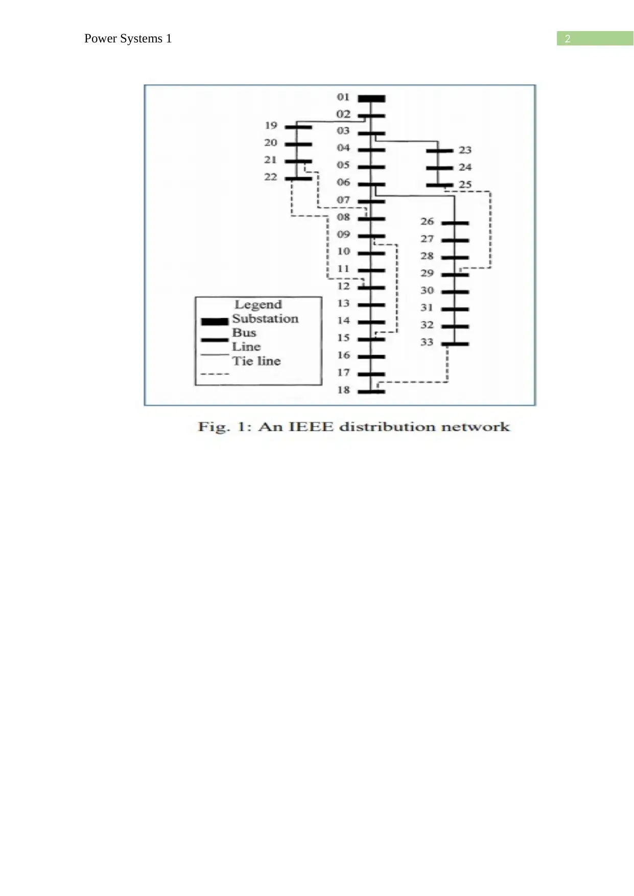
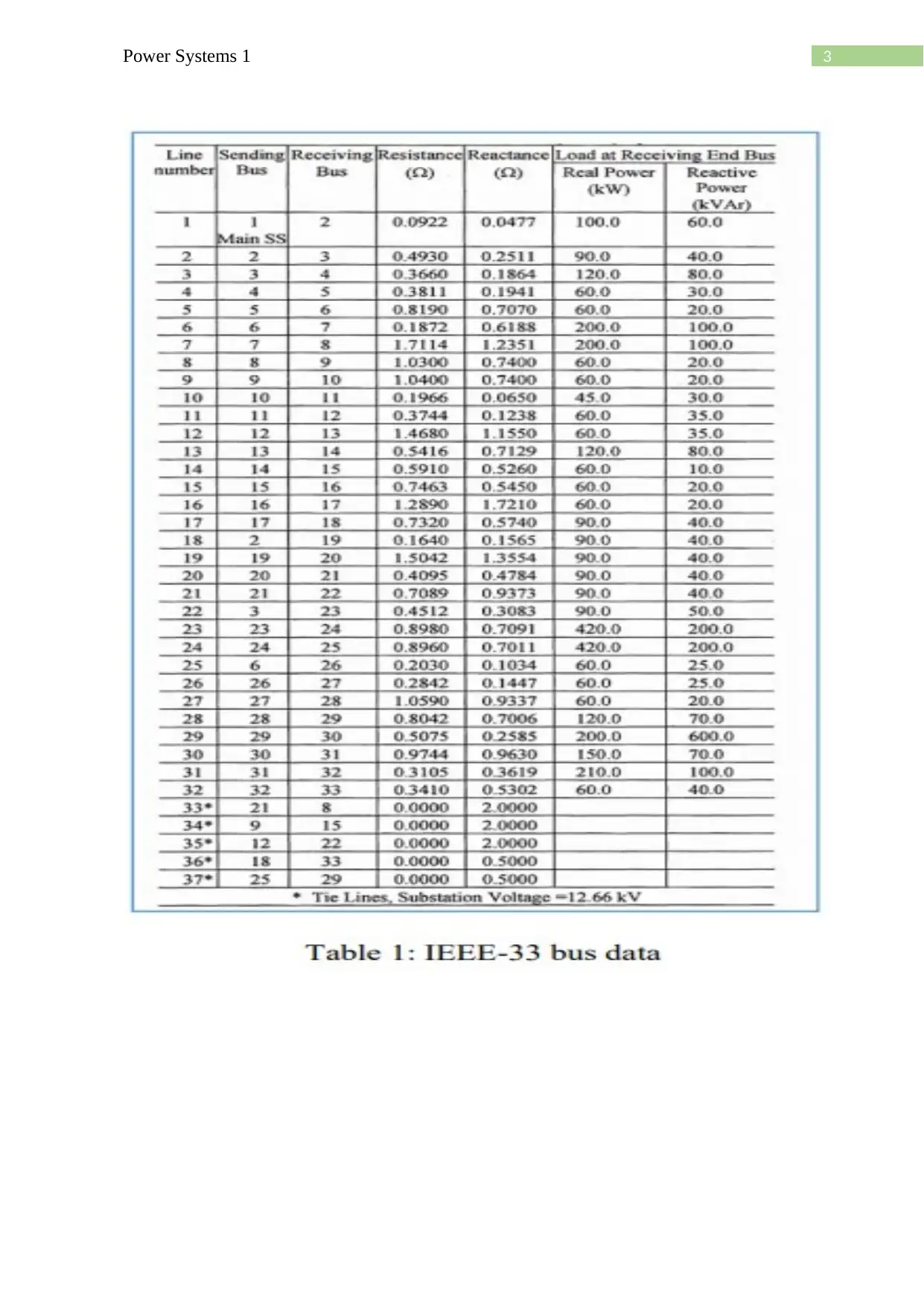
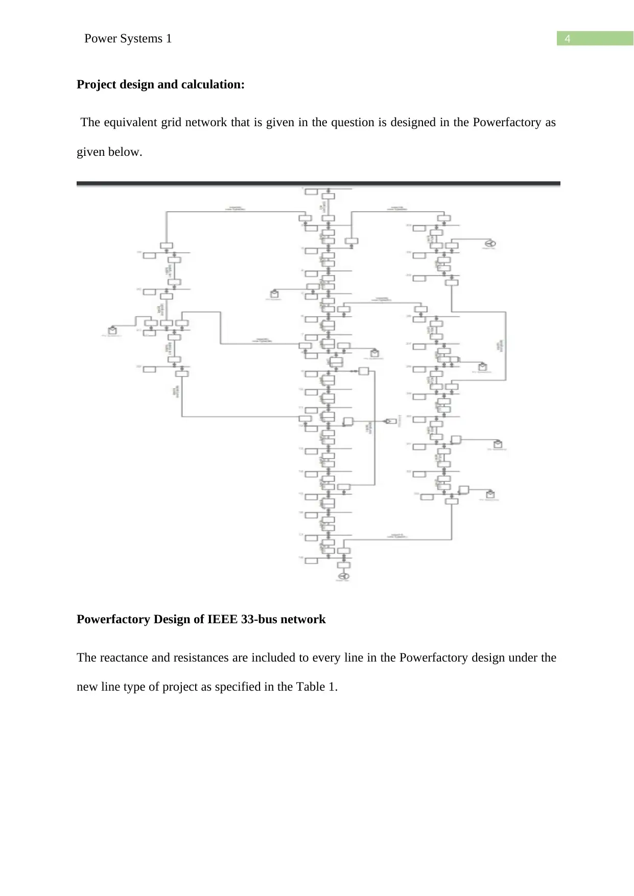
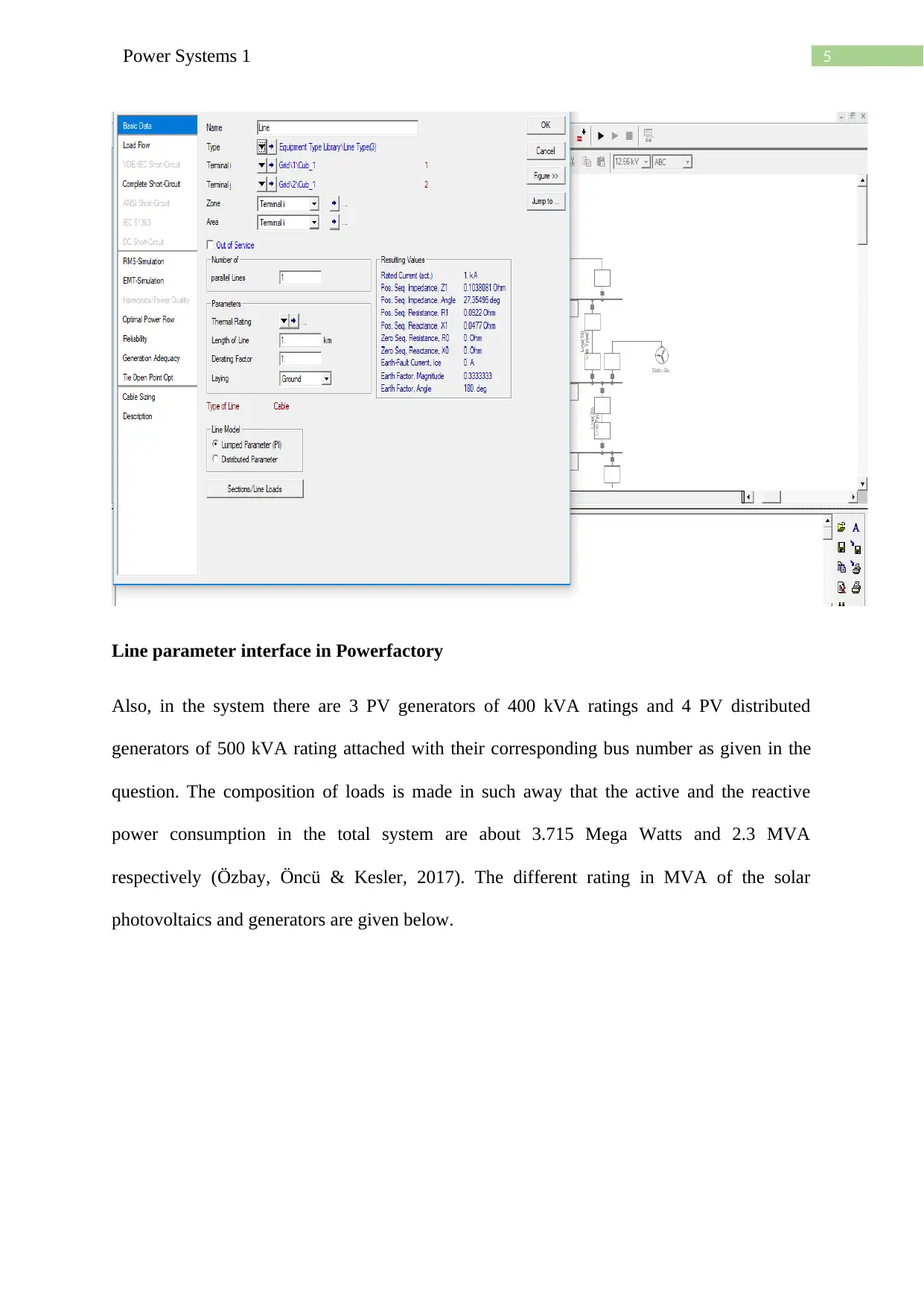
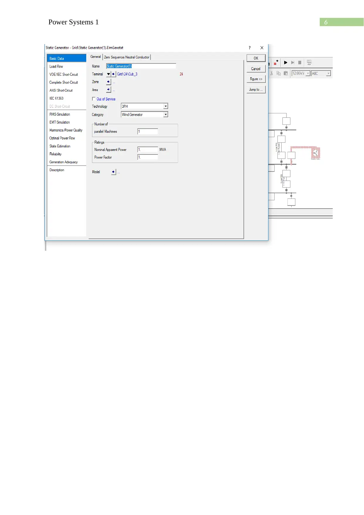
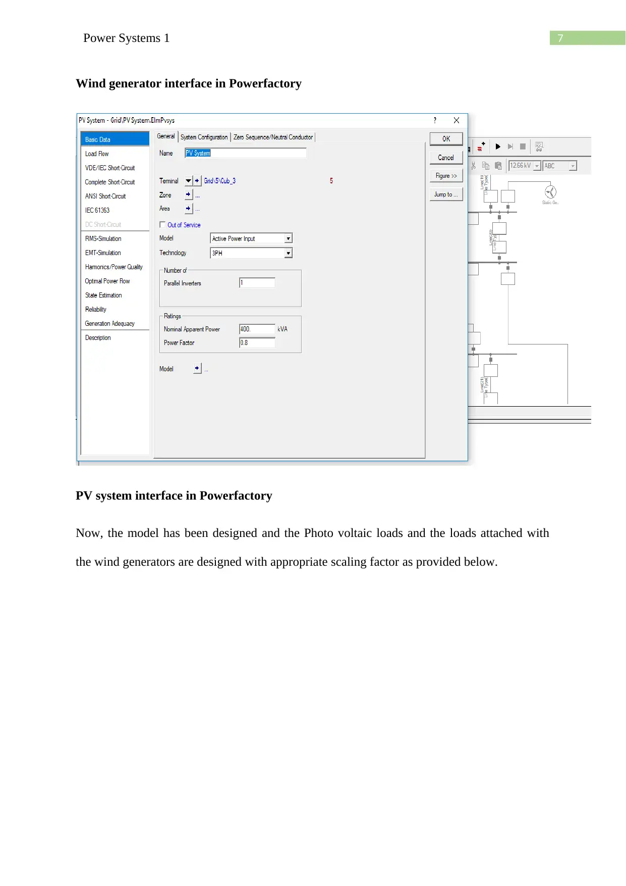
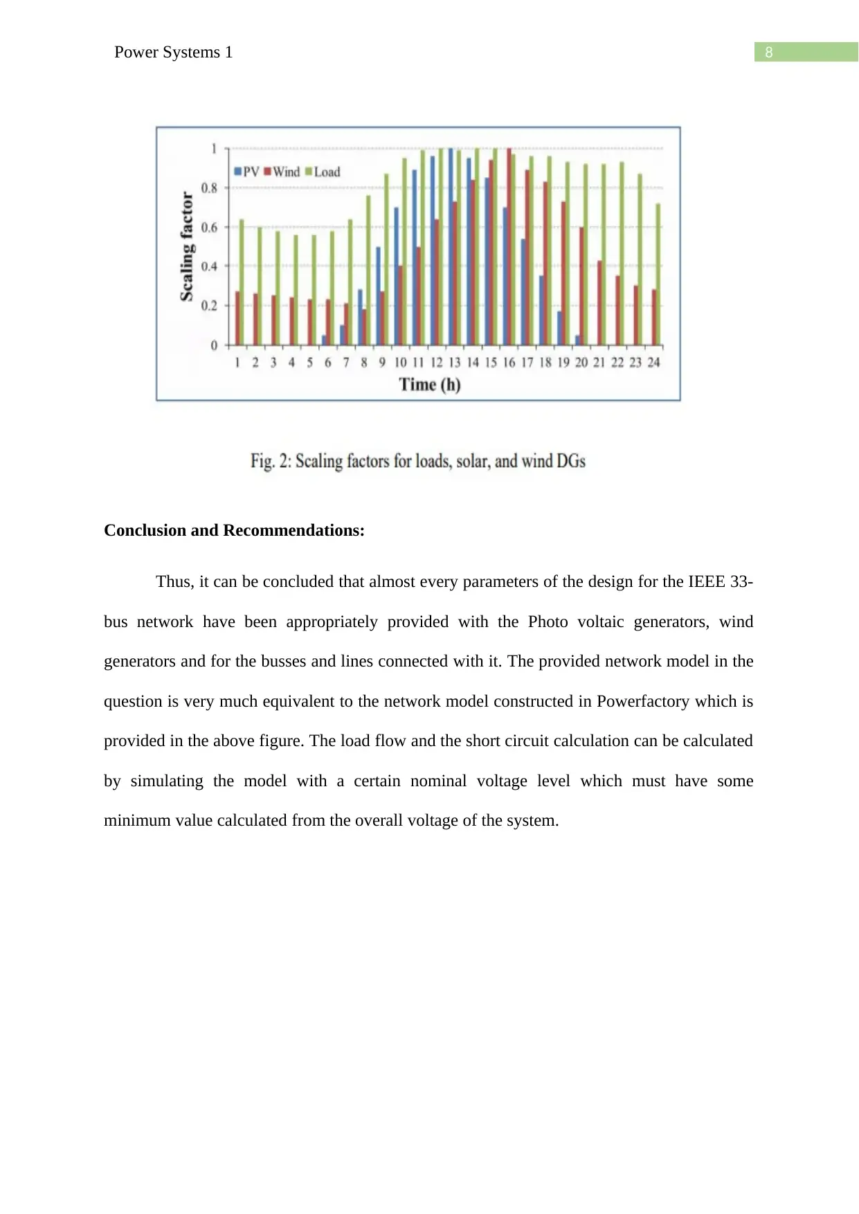
This project focuses on designing the power distribution network of the IEEE 33-bus system using Digsilent's Powerfactory software. The design includes load flow calculations to determine apparent, real, and reactive power, along with line losses. The base substation voltage is 12.66 kV with a 10 MVA rating. The system integrates solar PV panels and wind generators at different buses, with bus 1 serving as the main substation. The report details the Powerfactory design, including resistance and reactance values for lines, and the integration of PV and wind generators with appropriate ratings and scaling factors. The model replicates the provided network, enabling load flow and short circuit calculations through simulation at a specified nominal voltage level.
1 out of 10
Related Documents


Your All-in-One AI-Powered Toolkit for Academic Success.
+13062052269
info@desklib.com
Available 24*7 on WhatsApp / Email
![[object Object]](/_next/static/media/star-bottom.7253800d.svg)
Copyright © 2020–2026 A2Z Services. All Rights Reserved. Developed and managed by ZUCOL.