Power Electronic Applications for Energy Systems Solutions
VerifiedAdded on 2020/05/16
|3
|729
|162
Homework Assignment
AI Summary
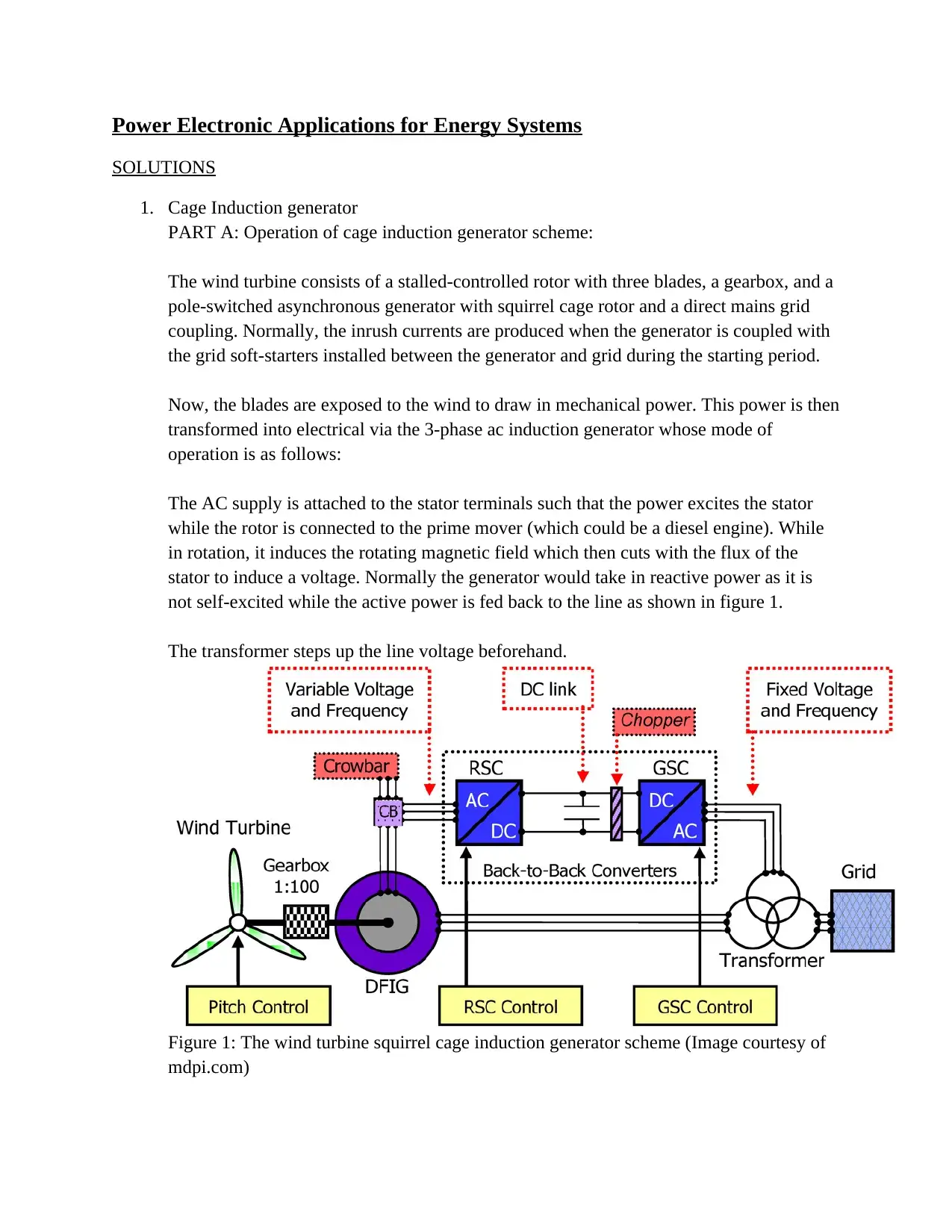
This document presents solutions to a power electronics assignment focused on energy systems. Part A explains the operation of a cage induction generator scheme, including the role of soft-starters and the transformation of mechanical power to electrical power in a wind turbine setup. It details the stator and rotor interactions, the rotating magnetic field, and the advantages of varying the generator's speed. Part B delves into self-excited induction generators, outlining their operational mechanism without external sources and their application in wind turbines, both in fixed-speed and variable-speed systems. It includes a calculation for the minimum capacitance required per phase in a delta-connected machine. The document also explains the generating mode of operation of a wound-rotor doubly-fed induction generator (DFIG) with the aid of power flow diagrams and equations, covering sub-synchronous and super-synchronous speeds and the role of voltage source converters.
1 out of 3


![[object Object]](/_next/static/media/star-bottom.7253800d.svg)