Power Electronics and Drive Systems in Ford Electric Vehicles Analysis
VerifiedAdded on 2022/12/01
|16
|2471
|308
Report
AI Summary
This report delves into the application of power electronics and drive systems within Ford electric vehicles, examining the core components and their functionalities. It explores the role of power electronics in converting AC and DC power, as well as the implementation of rectifiers, battery controllers, and electric motors. The report details the design and simulation of both DC and AC motor speed control systems, utilizing PSIM and MATLAB for analysis. The findings highlight the correlation between duty cycle and motor speed in DC drives, and the impact of frequency on synchronous motor speed in AC drives. The report also covers the utilization of Brushless DC motors and their controllers, providing a comprehensive overview of the technologies involved in electric vehicle drive systems.
Power Electronics and Drive systems 1
Title
Power Electronics and Drive systems
Student’s Name
Student’s Number
Class
Date
Title
Power Electronics and Drive systems
Student’s Name
Student’s Number
Class
Date
Paraphrase This Document
Need a fresh take? Get an instant paraphrase of this document with our AI Paraphraser
Power Electronics and Drive systems 2
Table of Contents
1. Ford Motor Company..........................................................................................................................3
2. Power Electronics and Drive systems in Electric Vehicles..................................................................3
3. Power Electronics and Drive System application in Electric Vehicle..................................................4
Rectifiers;................................................................................................................................................5
Battery controller/D.C-D.C converters....................................................................................................5
Electric motors and Motor Controller......................................................................................................6
Brushless DC motor and Controller.........................................................................................................6
Controller and sensors.............................................................................................................................6
4. A.C and D.C motor Speed Design and Simulation..............................................................................7
System design of D.C drive and simulation in PSIM...............................................................................7
System Design of A.C drive and Simulation in Matlab...........................................................................8
5. Results and analysis.............................................................................................................................9
Results and Analysis of the D.C drive system simulation........................................................................9
Results and Analysis of the A.C drive system simulation......................................................................11
6. Summary and Conclusion..................................................................................................................13
7. Appendix............................................................................................................................................14
References.............................................................................................................................................14
2018 Ford Focus Electric Brochure........................................................................................................15
Power Electronics and Drive systems 3
1. Ford Motor Company
Power electronics is utilization of solid state electronic switching devices that control electrical
power and related devices. Over the ages, there has been a tremendous advancement in the field
of power electronics. Industrial automations have been largely as a result of power electronics
dynamics. In modernized industries, power electronic drives are used to control either A.C or
D.C motors by varying electrical power quantities such as frequency or voltages.
In this report, application of power electronics and drive systems in electric cars manufactured
by Ford Motor company has been extensively studied. Ford Motor company headquartered in
Dearborn, Michigan, was founded by Henry Ford. This company manufactures cars in large-
scale applying extensive engineering technology. The company reiterated its plans to heavily
invest billions for production of more electric cars by 2022. According Bradley Berman (2019), a
US based columnist reports that in the year 1914, Ford began prototyping on electric cars that
could cost less dollars after being encouraged by what Thomas Edison, then a friend, was
experimenting with technology for battery powered vehicles. Many impedances on how to build
powerful and light batteries for longer distances derailed the process. As the years went by, Ford
Motor company build the Range EV from 1998-2002 (Bradley Berman,2019).
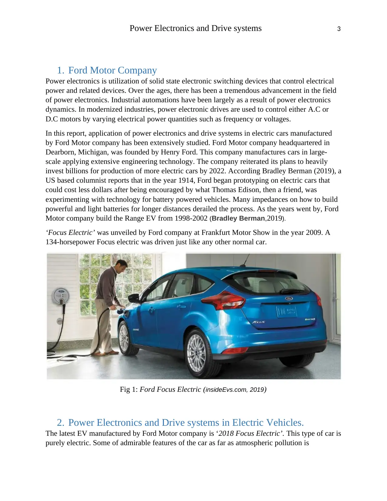
‘Focus Electric’ was unveiled by Ford company at Frankfurt Motor Show in the year 2009. A
134-horsepower Focus electric was driven just like any other normal car.
Fig 1: Ford Focus Electric (insideEvs.com, 2019)
2. Power Electronics and Drive systems in Electric Vehicles.
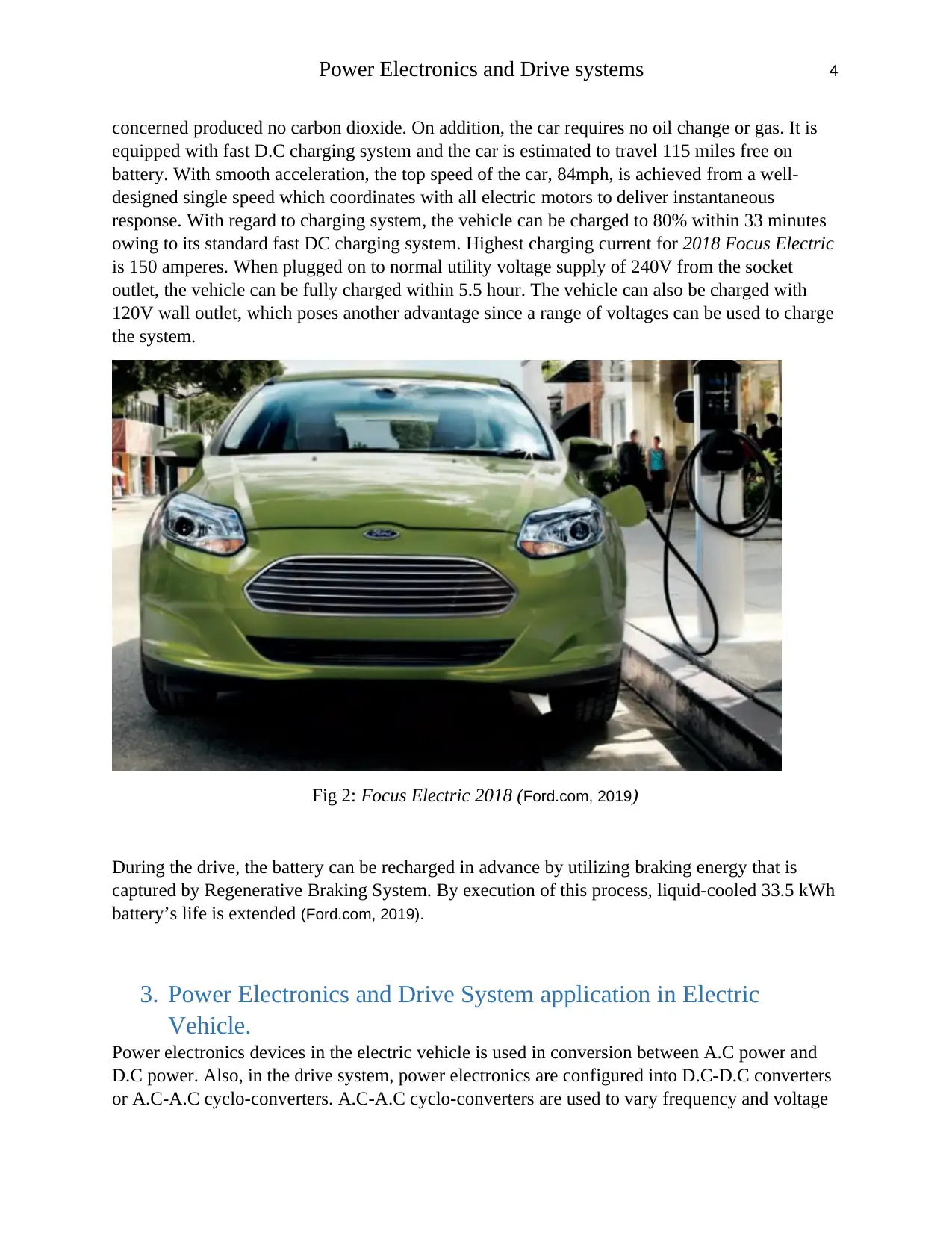
The latest EV manufactured by Ford Motor company is ‘2018 Focus Electric’. This type of car is
purely electric. Some of admirable features of the car as far as atmospheric pollution is
⊘ This is a preview!⊘
Do you want full access?
Subscribe today to unlock all pages.

Trusted by 1+ million students worldwide
Power Electronics and Drive systems 4
concerned produced no carbon dioxide. On addition, the car requires no oil change or gas. It is
equipped with fast D.C charging system and the car is estimated to travel 115 miles free on
battery. With smooth acceleration, the top speed of the car, 84mph, is achieved from a well-
designed single speed which coordinates with all electric motors to deliver instantaneous
response. With regard to charging system, the vehicle can be charged to 80% within 33 minutes
owing to its standard fast DC charging system. Highest charging current for 2018 Focus Electric
is 150 amperes. When plugged on to normal utility voltage supply of 240V from the socket
outlet, the vehicle can be fully charged within 5.5 hour. The vehicle can also be charged with
120V wall outlet, which poses another advantage since a range of voltages can be used to charge
the system.
Fig 2: Focus Electric 2018 (Ford.com, 2019)
During the drive, the battery can be recharged in advance by utilizing braking energy that is
captured by Regenerative Braking System. By execution of this process, liquid-cooled 33.5 kWh
battery’s life is extended (Ford.com, 2019).
3. Power Electronics and Drive System application in Electric
Vehicle.
Power electronics devices in the electric vehicle is used in conversion between A.C power and
D.C power. Also, in the drive system, power electronics are configured into D.C-D.C converters
or A.C-A.C cyclo-converters. A.C-A.C cyclo-converters are used to vary frequency and voltage
Paraphrase This Document
Need a fresh take? Get an instant paraphrase of this document with our AI Paraphraser
Power Electronics and Drive systems 5
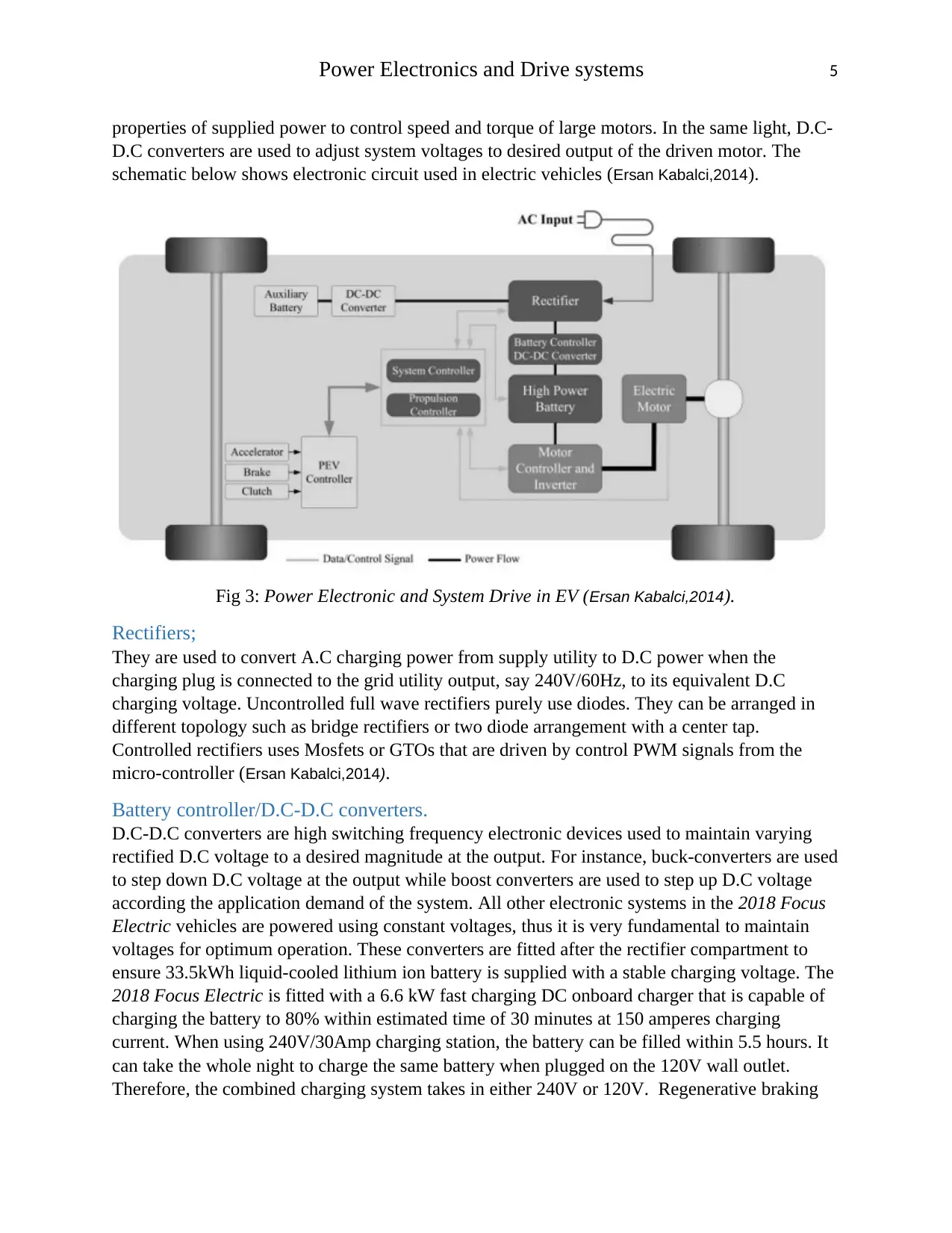
properties of supplied power to control speed and torque of large motors. In the same light, D.C-
D.C converters are used to adjust system voltages to desired output of the driven motor. The
schematic below shows electronic circuit used in electric vehicles (Ersan Kabalci,2014).
Fig 3: Power Electronic and System Drive in EV (Ersan Kabalci,2014).
Rectifiers;
They are used to convert A.C charging power from supply utility to D.C power when the
charging plug is connected to the grid utility output, say 240V/60Hz, to its equivalent D.C
charging voltage. Uncontrolled full wave rectifiers purely use diodes. They can be arranged in
different topology such as bridge rectifiers or two diode arrangement with a center tap.
Controlled rectifiers uses Mosfets or GTOs that are driven by control PWM signals from the
micro-controller (Ersan Kabalci,2014).
Battery controller/D.C-D.C converters.
D.C-D.C converters are high switching frequency electronic devices used to maintain varying
rectified D.C voltage to a desired magnitude at the output. For instance, buck-converters are used
to step down D.C voltage at the output while boost converters are used to step up D.C voltage
according the application demand of the system. All other electronic systems in the 2018 Focus
Electric vehicles are powered using constant voltages, thus it is very fundamental to maintain
voltages for optimum operation. These converters are fitted after the rectifier compartment to
ensure 33.5kWh liquid-cooled lithium ion battery is supplied with a stable charging voltage. The
2018 Focus Electric is fitted with a 6.6 kW fast charging DC onboard charger that is capable of
charging the battery to 80% within estimated time of 30 minutes at 150 amperes charging
current. When using 240V/30Amp charging station, the battery can be filled within 5.5 hours. It
can take the whole night to charge the same battery when plugged on the 120V wall outlet.
Therefore, the combined charging system takes in either 240V or 120V. Regenerative braking
Power Electronics and Drive systems 6
system recharges the battery with energy released in braking. The operator maximizes on braking
energy harvest using brake coach screen (Ford.com, 2019).
Brushless D.C motors are also controlled by D.C-D.C converters. Converters for this operation
vary speed and torque of the driving wheels by adjusting currents and voltages supplied to the
motors. This chain of operation is accomplished by using buck-boost converter.
Electric motors and Motor Controller.
Motors in electric vehicles are used to convert electric energy to mechanical energy that is
transferred to the wheels for traction. Electric motors used are selected based on the construction,
speed range, efficiency, electromagnetic interference among others. For 2018 Focus Electric,
107kW electric motors whose rated power are 143 Horsepower are used. These motors are fitted
with sensors which relay feedback signals to the machine controllers, basically made of power
electronic devices, which in response sends command signals to either increase speed at constant
torque or increase torque. Speed adjustment can be further expedited using gear train when
smaller size of the is used. The 2018 Focus Electric speed control is designed such that when
accelerator is pressed, speed and torque transmission in relayed to all electric motors using
electronic devices. The top speed for this EV is 84mph.
Brushless DC motor and Controller.
Brushless DC motor (BLDC) are commonly preferred because they operate at high frequency.
This motor is an ordinary A.C motor incorporated with rotor position sensors and semiconductor
inverter control. These motors are compact and in operation, they run like a classical D.C motor
with a stead linear moment-speed properties. Rotor position sensors and semiconductor inverter
control are actualized using hall-effect sensors techniques. Hall sensors produces current
waveforms proportional to the speed and position of the rotor, which is fed into the micro-
controller.
Controller and sensors.
Signals used to control power electronic are generated by micro-controllers. Micro-controllers
are used to tune power electronics and electronic switched to maintain constant speed and torque.
The controllers respond to currents and voltages feedbacks relayed by sensors confined in
specific parts of the electric vehicle.
⊘ This is a preview!⊘
Do you want full access?
Subscribe today to unlock all pages.

Trusted by 1+ million students worldwide
Power Electronics and Drive systems 7
4. A.C and D.C motor Speed Design and Simulation
System design of D.C drive and simulation in PSIM.
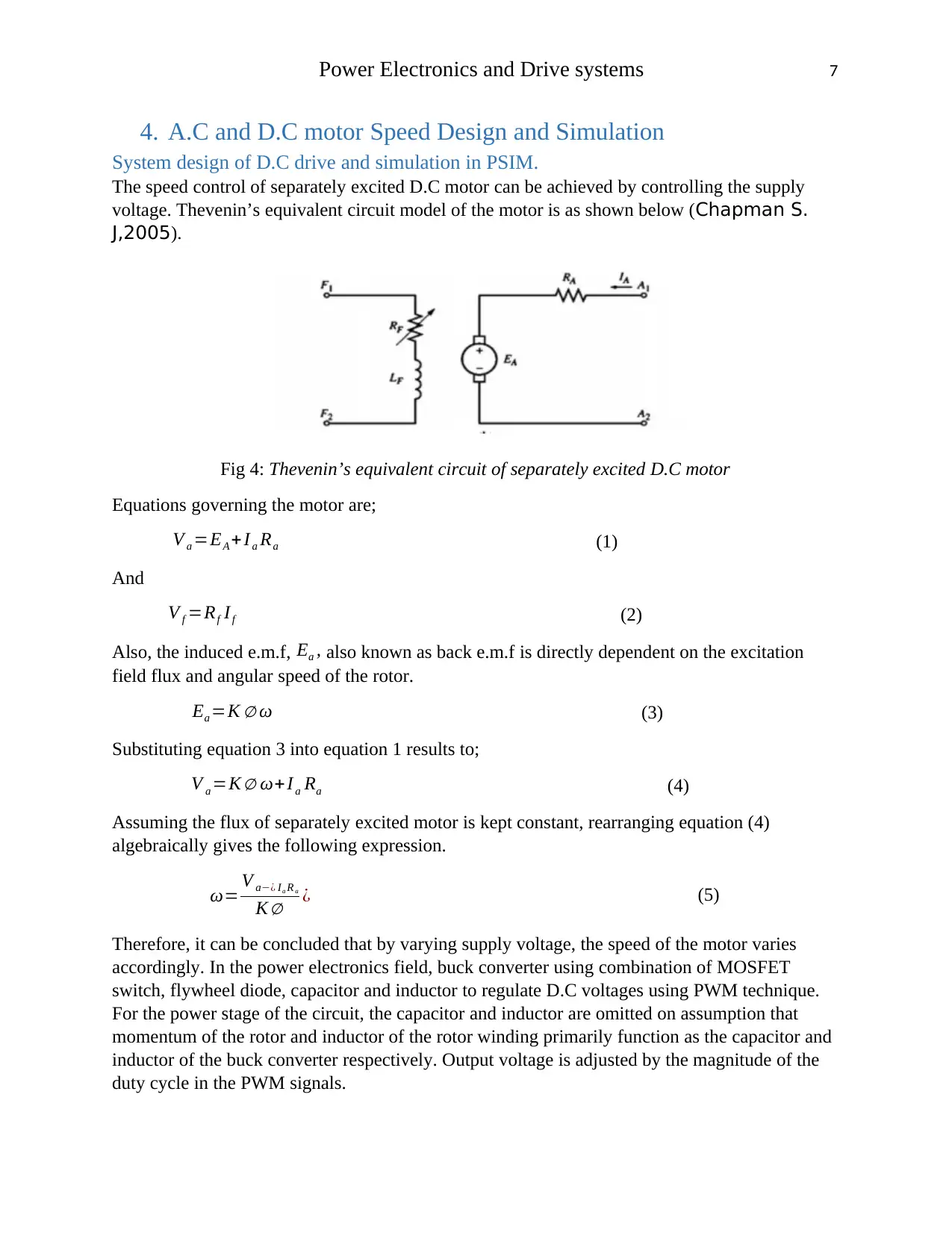
The speed control of separately excited D.C motor can be achieved by controlling the supply
voltage. Thevenin’s equivalent circuit model of the motor is as shown below (Chapman S.
J,2005).
Fig 4: Thevenin’s equivalent circuit of separately excited D.C motor
Equations governing the motor are;
V a =EA + Ia Ra (1)
And
V f =Rf If (2)
Also, the induced e.m.f, Ea , also known as back e.m.f is directly dependent on the excitation
field flux and angular speed of the rotor.
Ea =K ∅ ω (3)
Substituting equation 3 into equation 1 results to;
V a =K ∅ ω+ I a Ra (4)
Assuming the flux of separately excited motor is kept constant, rearranging equation (4)
algebraically gives the following expression.
ω= V a−¿ Ia R a
K ∅ ¿ (5)
Therefore, it can be concluded that by varying supply voltage, the speed of the motor varies
accordingly. In the power electronics field, buck converter using combination of MOSFET
switch, flywheel diode, capacitor and inductor to regulate D.C voltages using PWM technique.
For the power stage of the circuit, the capacitor and inductor are omitted on assumption that
momentum of the rotor and inductor of the rotor winding primarily function as the capacitor and
inductor of the buck converter respectively. Output voltage is adjusted by the magnitude of the
duty cycle in the PWM signals.
Paraphrase This Document
Need a fresh take? Get an instant paraphrase of this document with our AI Paraphraser
Power Electronics and Drive systems 8
D= ON
ON +OFF (6)
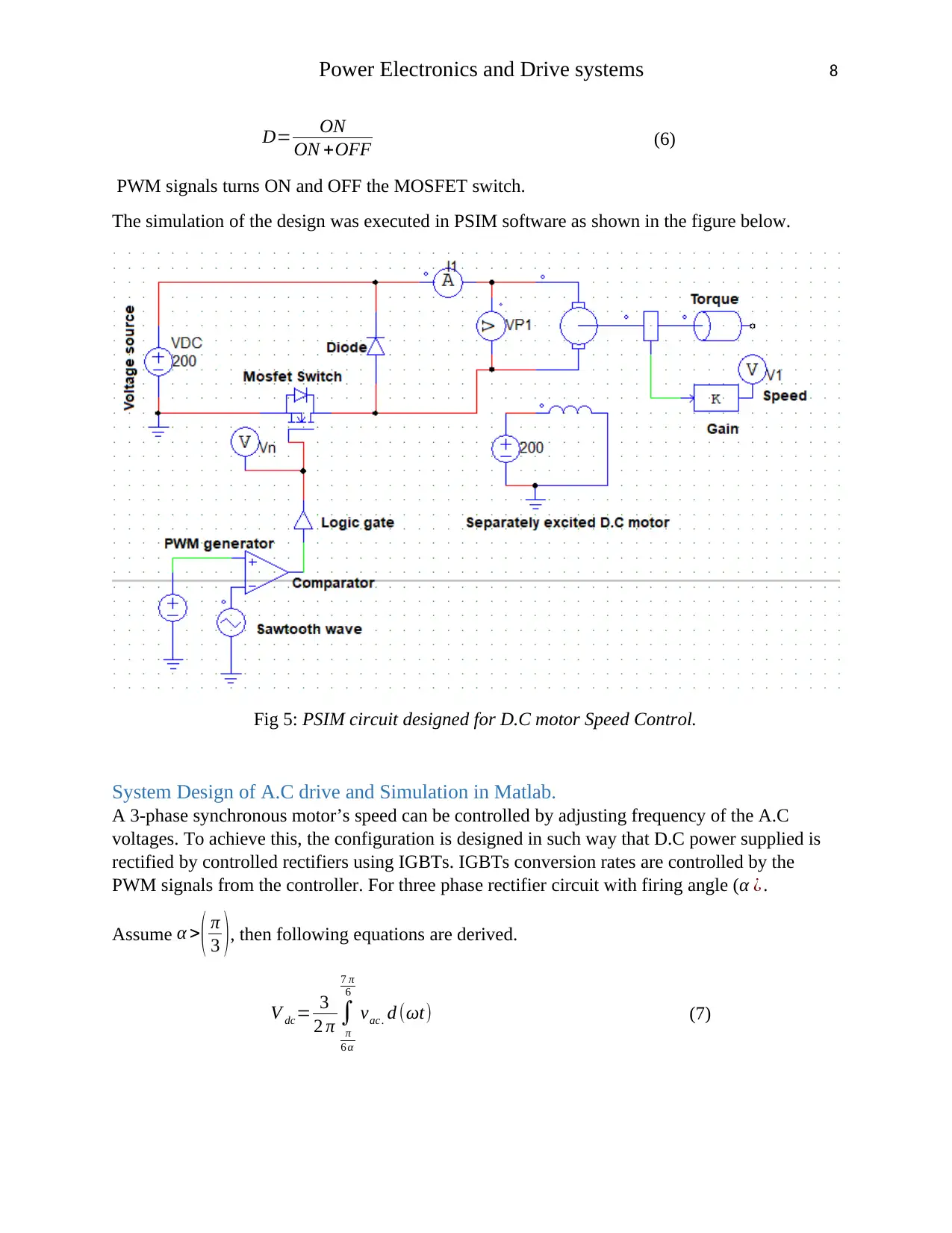
PWM signals turns ON and OFF the MOSFET switch.
The simulation of the design was executed in PSIM software as shown in the figure below.
Fig 5: PSIM circuit designed for D.C motor Speed Control.
System Design of A.C drive and Simulation in Matlab.
A 3-phase synchronous motor’s speed can be controlled by adjusting frequency of the A.C
voltages. To achieve this, the configuration is designed in such way that D.C power supplied is
rectified by controlled rectifiers using IGBTs. IGBTs conversion rates are controlled by the
PWM signals from the controller. For three phase rectifier circuit with firing angle (α ¿ .
Assume α >( π
3 ), then following equations are derived.
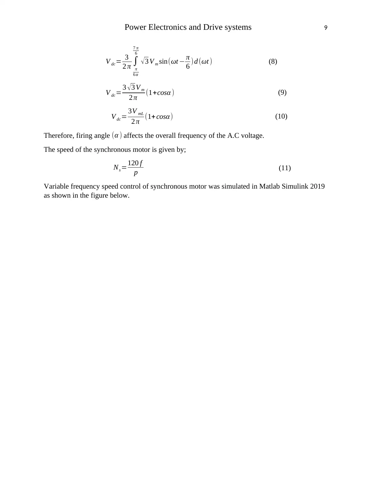
V dc= 3
2 π ∫
π
6 α
7 π
6
vac . d (ωt) (7)
Power Electronics and Drive systems 9
V dc= 3
2 π ∫
π
6 α
7 π
6
√ 3 V m sin(ωt − π
6 ) d (ωt ) (8)
V dc= 3 √3 V m
2 π (1+cosα ) (9)
V dc= 3V mL
2 π (1+cosα) (10)
Therefore, firing angle (α ) affects the overall frequency of the A.C voltage.
The speed of the synchronous motor is given by;
Ns =120 f
p (11)
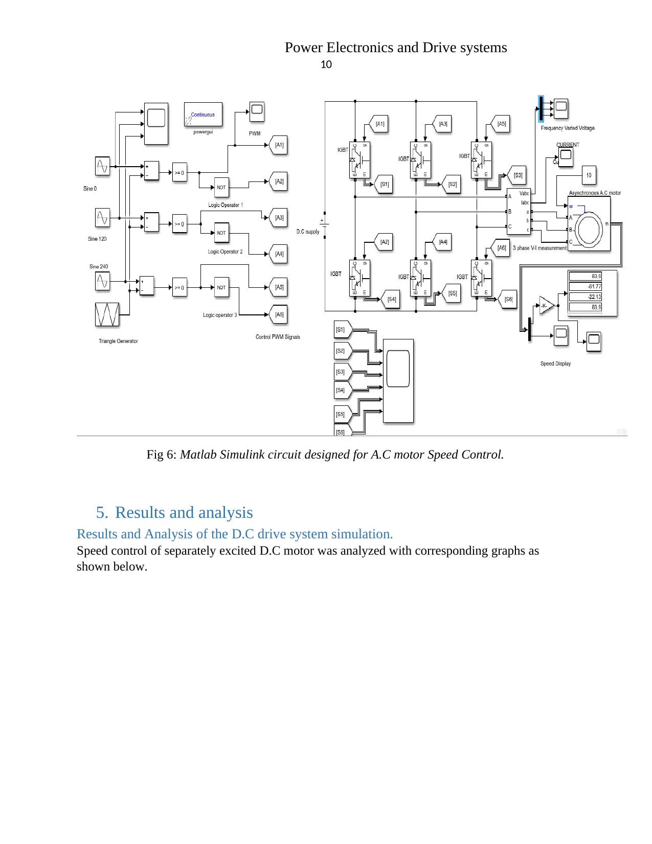
Variable frequency speed control of synchronous motor was simulated in Matlab Simulink 2019
as shown in the figure below.
⊘ This is a preview!⊘
Do you want full access?
Subscribe today to unlock all pages.

Trusted by 1+ million students worldwide
Power Electronics and Drive systems
10
Fig 6: Matlab Simulink circuit designed for A.C motor Speed Control.
5. Results and analysis
Results and Analysis of the D.C drive system simulation.
Speed control of separately excited D.C motor was analyzed with corresponding graphs as
shown below.
10
Fig 6: Matlab Simulink circuit designed for A.C motor Speed Control.
5. Results and analysis
Results and Analysis of the D.C drive system simulation.
Speed control of separately excited D.C motor was analyzed with corresponding graphs as
shown below.
Paraphrase This Document
Need a fresh take? Get an instant paraphrase of this document with our AI Paraphraser
Power Electronics and Drive systems
11
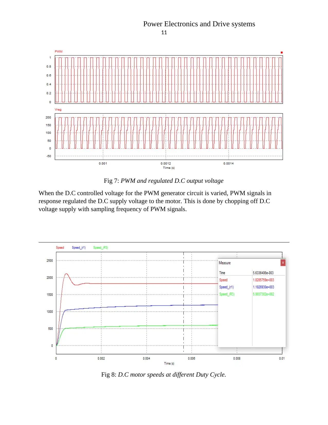
Fig 7: PWM and regulated D.C output voltage
When the D.C controlled voltage for the PWM generator circuit is varied, PWM signals in
response regulated the D.C supply voltage to the motor. This is done by chopping off D.C
voltage supply with sampling frequency of PWM signals.
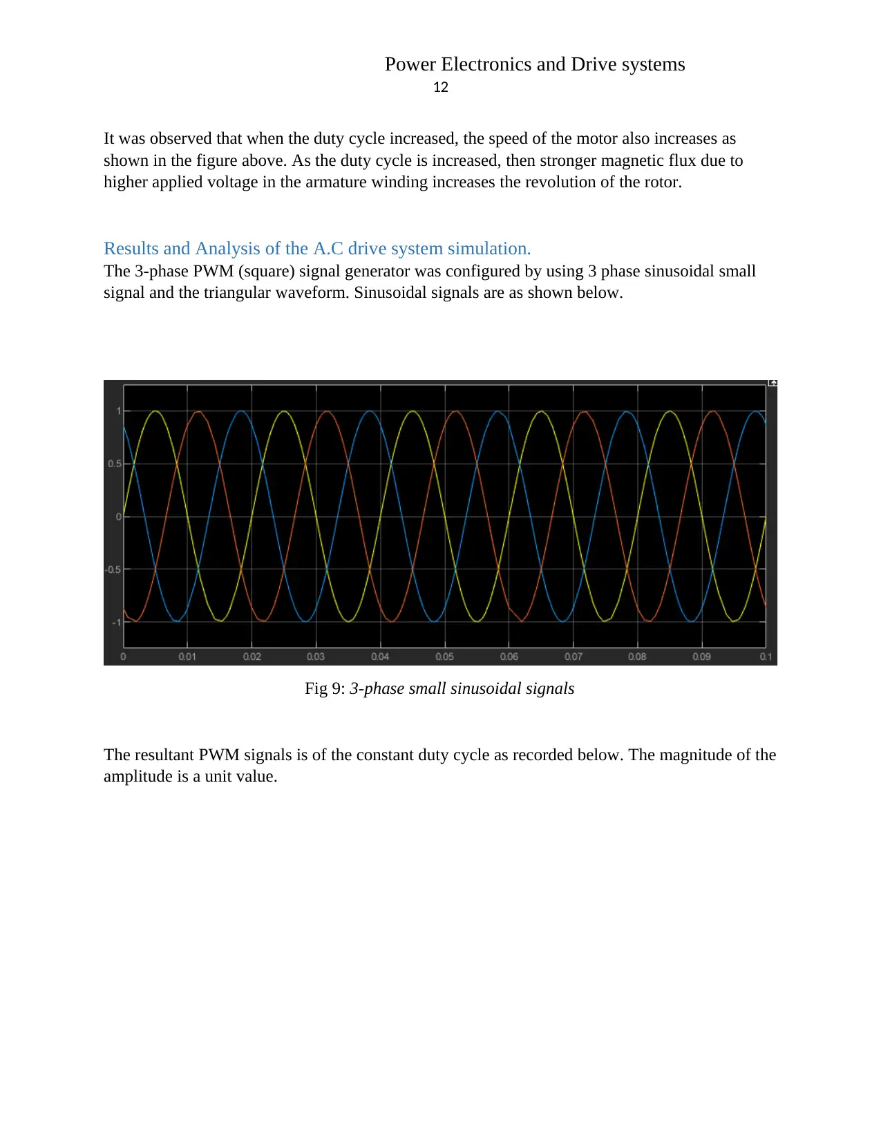
Fig 8: D.C motor speeds at different Duty Cycle.
Power Electronics and Drive systems
12
It was observed that when the duty cycle increased, the speed of the motor also increases as
shown in the figure above. As the duty cycle is increased, then stronger magnetic flux due to
higher applied voltage in the armature winding increases the revolution of the rotor.
Results and Analysis of the A.C drive system simulation.
The 3-phase PWM (square) signal generator was configured by using 3 phase sinusoidal small
signal and the triangular waveform. Sinusoidal signals are as shown below.
Fig 9: 3-phase small sinusoidal signals
The resultant PWM signals is of the constant duty cycle as recorded below. The magnitude of the
amplitude is a unit value.
⊘ This is a preview!⊘
Do you want full access?
Subscribe today to unlock all pages.

Trusted by 1+ million students worldwide
1 out of 16
Related Documents
Your All-in-One AI-Powered Toolkit for Academic Success.
+13062052269
info@desklib.com
Available 24*7 on WhatsApp / Email
![[object Object]](/_next/static/media/star-bottom.7253800d.svg)
Unlock your academic potential
Copyright © 2020–2025 A2Z Services. All Rights Reserved. Developed and managed by ZUCOL.


