Power Electronics and System Drives: Al Fadhili Substation Report
VerifiedAdded on 2022/11/29
|16
|2075
|484
Report
AI Summary
This report provides a detailed analysis of power electronics and system drives, focusing on their application within the Gulf Cooperation Council (GCC) interconnection, specifically the Al Fadhili back-to-back converter substation. The report begins with an introduction to High Voltage Direct Current (HVDC) transmission systems and the role of power electronics in converter substations. It explores the GCC's energy demands, the interconnection project, and the functionality of the Al Fadhili substation. The report then delves into the design and simulation of a battery charger using a boost converter and a frequency-controlled synchronous motor based on an AC drive system. It includes circuit diagrams, equations, and simulation results obtained using PSIM software. The findings highlight the relationship between control voltage and output voltage in the battery charger, as well as the impact of frequency on the speed of the synchronous motor. The report concludes by summarizing the key findings and emphasizing the importance of power electronics in controlling large-scale systems. References to relevant sources are also provided.

Power Electronics and System Drives 1
Title
Power Electronics and System Drives
Student’s Name
Student’s Number
Class
Date
Title
Power Electronics and System Drives
Student’s Name
Student’s Number
Class
Date
Paraphrase This Document
Need a fresh take? Get an instant paraphrase of this document with our AI Paraphraser
Power Electronics and System Drives 2
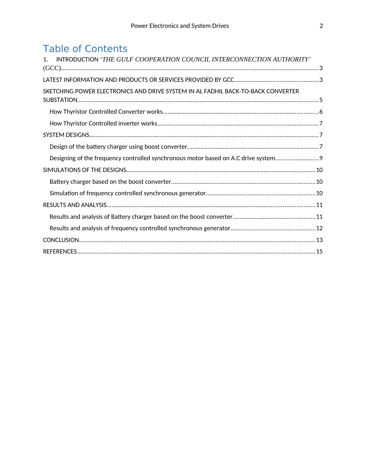
Table of Contents
1. INTRODUCTION ‘THE GULF COOPERATION COUNCIL INTERCONNECTION AUTHORITY’
(GCC)..........................................................................................................................................................3
LATEST INFORMATION AND PRODUCTS OR SERVICES PROVIDED BY GCC..................................................3
SKETCHING POWER ELECTRONICS AND DRIVE SYSTEM IN AL FADHIL BACK-TO-BACK CONVERTER
SUBSTATION................................................................................................................................................5
How Thyristor Controlled Converter works.............................................................................................6
How Thyristor Controlled inverter works................................................................................................7
SYSTEM DESIGNS.........................................................................................................................................7
Design of the battery charger using boost converter..............................................................................7
Designing of the frequency controlled synchronous motor based on A.C drive system..........................9
SIMULATIONS OF THE DESIGNS.................................................................................................................10
Battery charger based on the boost converter......................................................................................10
Simulation of frequency controlled synchronous generator.................................................................10
RESULTS AND ANALYSIS............................................................................................................................11
Results and analysis of Battery charger based on the boost converter.................................................11
Results and analysis of frequency controlled synchronous generator...................................................12
CONCLUSION.............................................................................................................................................13
REFERENCES..............................................................................................................................................15
Power Electronics and System Drives 3
1. INTRODUCTION ‘THE GULF COOPERATION COUNCIL INTERCONNECTION
AUTHORITY’ (GCC)
High Voltage Direct Current (HVDC) transmission is the electrical transmission system that
evacuated power using direct current. HVDC transmission system can also transfer power
between systems with unsynchronized A.C frequency. HVDC transmission system comprises of
the following fundamental components highlighted below;
i. Converter substation and converter units
ii. Converter valves and converter transformers
iii. A.C, D.C, and high frequency filters.
iv. Reactors and reactive power source
Conversion and inversion of power between A.C and D.C is coordinated by cascading converter
transformers and converter valves (Anshika R, 2019). In this report, the application of power
electronics and drive systems in the converter substation will be dealt with. There are different
types of HVDC converter substation namely; Back-to-back substation, two terminal HVDC
substation, and multi-terminal DC substation (Circuit Globe, 2019).
The case study is based on back-to-back converter substation of ‘The Gulf Cooperation Council
Interconnection Authority’ (GCC). This substation connected to 400kV grid was commissioned
in 2009, connecting Bahrain, Kuwait, Qatar, Oman, United Arab Emirates and Saudi Arabia. The
project has tremendously benefited GCC countries in terms of curbing power emergency. In the
first phase of construction, existing power grid system operating at 60 Hz, 380kV was merged to
50Hz, 400-kV interconnection system of Bahrain, Saudi Arabia, Qatar and Kuwait by installing
1200-WM back-to-back substation (Ahmed Ali Ebrahim, 2012).
HVDC back-to-back substation transmits A.C power between buses in the same location without
installing HVDC transmission lines. The 1200-MW back-to-back substation provided an
asynchronous connection between independently controlled 60Hz, 380 kV power grid and 50Hz,
400-kV power grid without transferring frequency disturbances.
LATEST INFORMATION AND PRODUCTS OR SERVICES PROVIDED BY GCC.
Project planning and actualization was driven by many factors including growth in energy
demand. High cost of oil and gases led to massive decline in consumption of oil and natural
gases. As a result, the phenomena spurred increase in demand of electricity, which then was
cheaper source of electric power. Also economic dynamics influenced by foreign investors and
industrialization of GCC countries triggered electric power interconnection deals among them. It
is recorded that the recent growth in energy demand for those GCC countries rose from 7% to
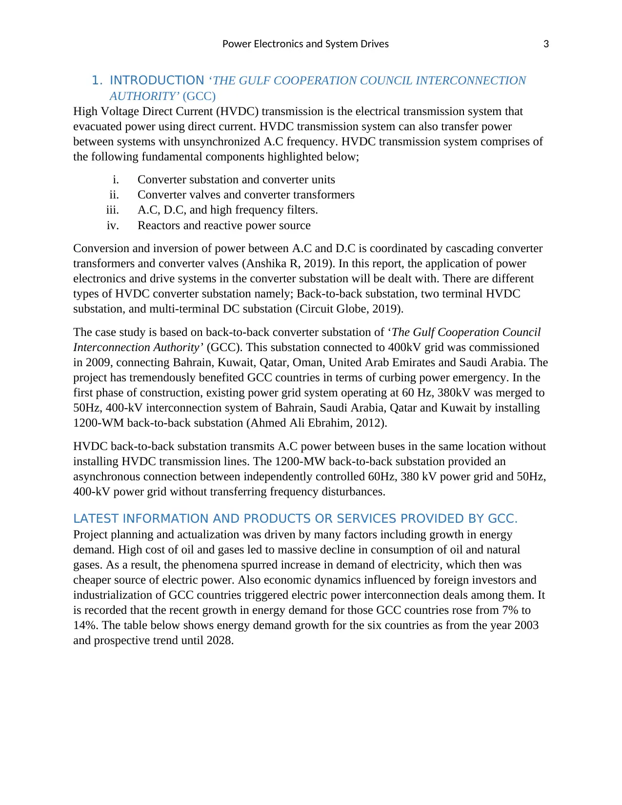
14%. The table below shows energy demand growth for the six countries as from the year 2003
and prospective trend until 2028.
⊘ This is a preview!⊘
Do you want full access?
Subscribe today to unlock all pages.

Trusted by 1+ million students worldwide
Power Electronics and System Drives 4
Table 1: GCC countries demand Growth in MW (Adnan Al-Mohaisen, 2019).
The trend has it that energy demand has been quantitatively increasing annually to an extend of
surpassing potential electricity production of some of the countries. The GCC countries had
therefore to collaborate in the aforementioned mega-project to quench energy deficit. However,
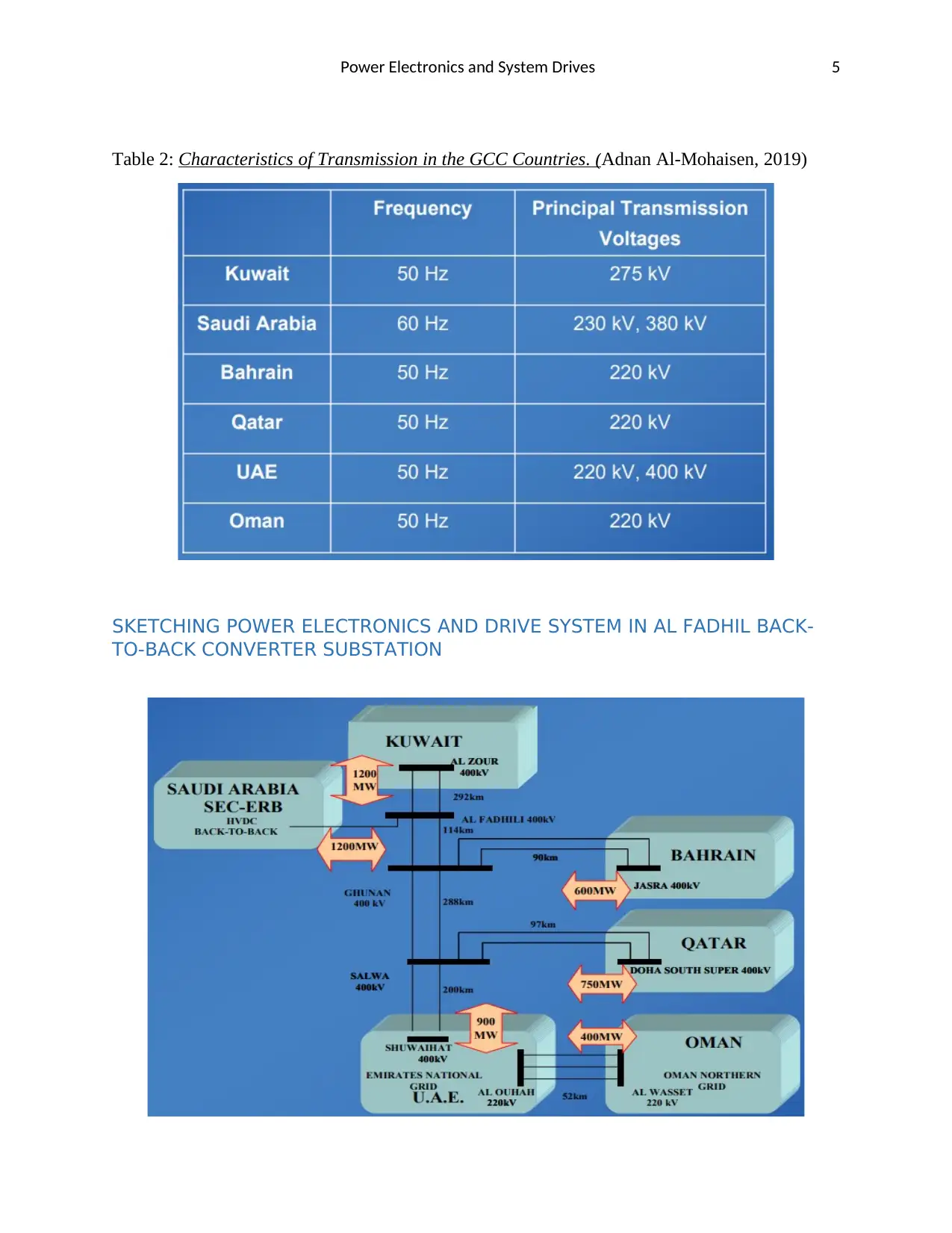
as shown in the table below, of the six countries, Saudi Arabia is operating its power at a
frequency of 60Hz as opposed to 50 Hz. For such un-avoided reasons, a double circuit 400Kv,
50Hz line from Al Zour, Kuwait is interconnected to Saudi Arabia 380-Kv, 60Hz line via a back-
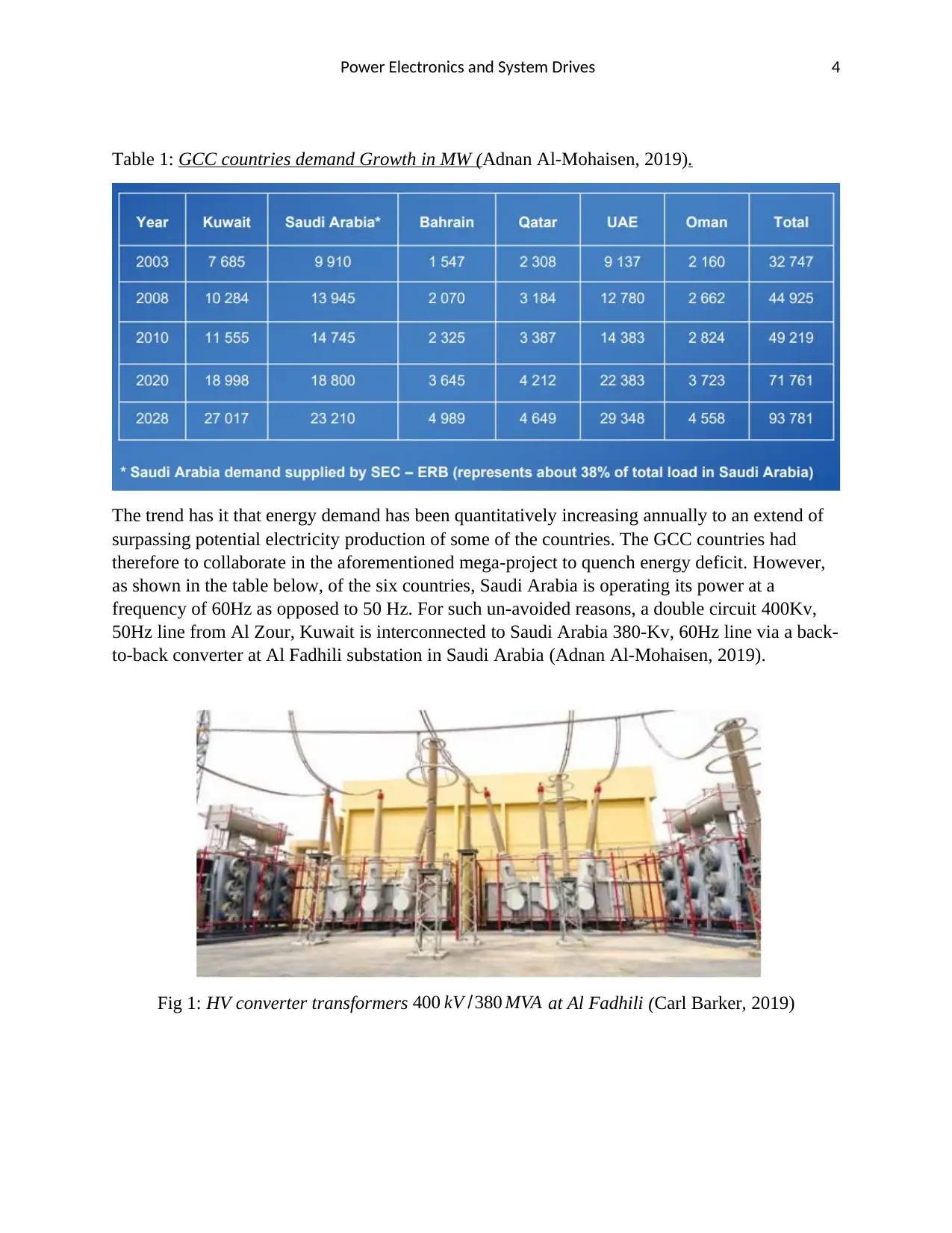
to-back converter at Al Fadhili substation in Saudi Arabia (Adnan Al-Mohaisen, 2019).
Fig 1: HV converter transformers 400 kV /380 MVA at Al Fadhili (Carl Barker, 2019)
Paraphrase This Document
Need a fresh take? Get an instant paraphrase of this document with our AI Paraphraser
Power Electronics and System Drives 5
Table 2: Characteristics of Transmission in the GCC Countries. (Adnan Al-Mohaisen, 2019)
SKETCHING POWER ELECTRONICS AND DRIVE SYSTEM IN AL FADHIL BACK-
TO-BACK CONVERTER SUBSTATION
Table 2: Characteristics of Transmission in the GCC Countries. (Adnan Al-Mohaisen, 2019)
SKETCHING POWER ELECTRONICS AND DRIVE SYSTEM IN AL FADHIL BACK-
TO-BACK CONVERTER SUBSTATION
Power Electronics and System Drives 6
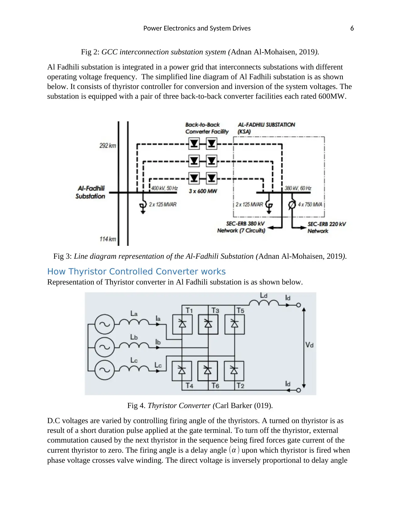
Fig 2: GCC interconnection substation system (Adnan Al-Mohaisen, 2019).
Al Fadhili substation is integrated in a power grid that interconnects substations with different
operating voltage frequency. The simplified line diagram of Al Fadhili substation is as shown
below. It consists of thyristor controller for conversion and inversion of the system voltages. The
substation is equipped with a pair of three back-to-back converter facilities each rated 600MW.
Fig 3: Line diagram representation of the Al-Fadhili Substation (Adnan Al-Mohaisen, 2019).
How Thyristor Controlled Converter works
Representation of Thyristor converter in Al Fadhili substation is as shown below.
Fig 4. Thyristor Converter (Carl Barker (019).
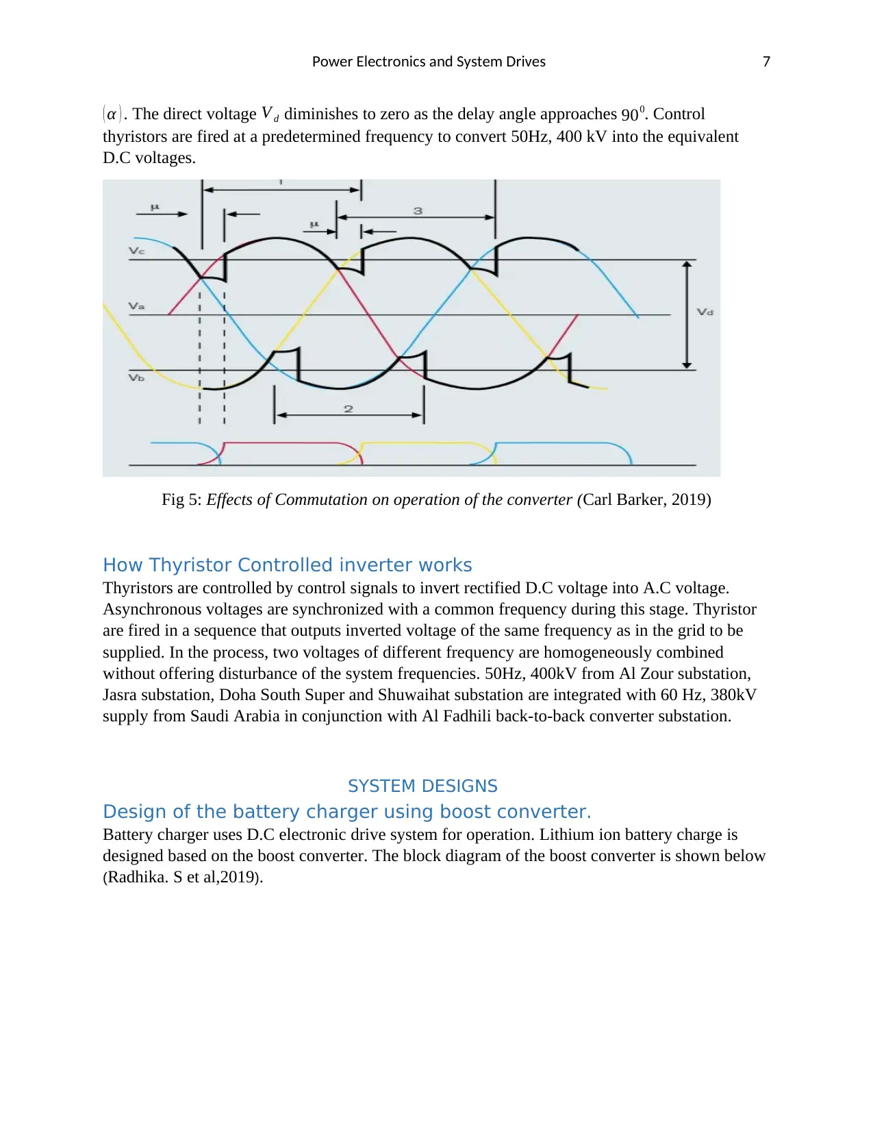
D.C voltages are varied by controlling firing angle of the thyristors. A turned on thyristor is as
result of a short duration pulse applied at the gate terminal. To turn off the thyristor, external
commutation caused by the next thyristor in the sequence being fired forces gate current of the
current thyristor to zero. The firing angle is a delay angle (α ) upon which thyristor is fired when
phase voltage crosses valve winding. The direct voltage is inversely proportional to delay angle
⊘ This is a preview!⊘
Do you want full access?
Subscribe today to unlock all pages.

Trusted by 1+ million students worldwide
Power Electronics and System Drives 7
( α ) . The direct voltage V d diminishes to zero as the delay angle approaches 900. Control
thyristors are fired at a predetermined frequency to convert 50Hz, 400 kV into the equivalent
D.C voltages.
Fig 5: Effects of Commutation on operation of the converter (Carl Barker, 2019)
How Thyristor Controlled inverter works
Thyristors are controlled by control signals to invert rectified D.C voltage into A.C voltage.
Asynchronous voltages are synchronized with a common frequency during this stage. Thyristor
are fired in a sequence that outputs inverted voltage of the same frequency as in the grid to be
supplied. In the process, two voltages of different frequency are homogeneously combined
without offering disturbance of the system frequencies. 50Hz, 400kV from Al Zour substation,
Jasra substation, Doha South Super and Shuwaihat substation are integrated with 60 Hz, 380kV
supply from Saudi Arabia in conjunction with Al Fadhili back-to-back converter substation.
SYSTEM DESIGNS
Design of the battery charger using boost converter.
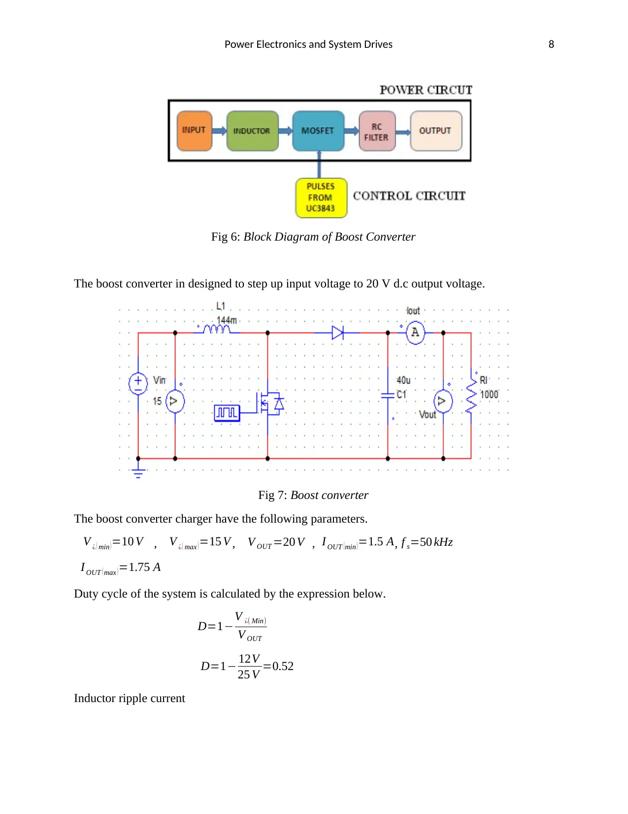
Battery charger uses D.C electronic drive system for operation. Lithium ion battery charge is
designed based on the boost converter. The block diagram of the boost converter is shown below
(Radhika. S et al,2019).
Paraphrase This Document
Need a fresh take? Get an instant paraphrase of this document with our AI Paraphraser
Power Electronics and System Drives 8
Fig 6: Block Diagram of Boost Converter
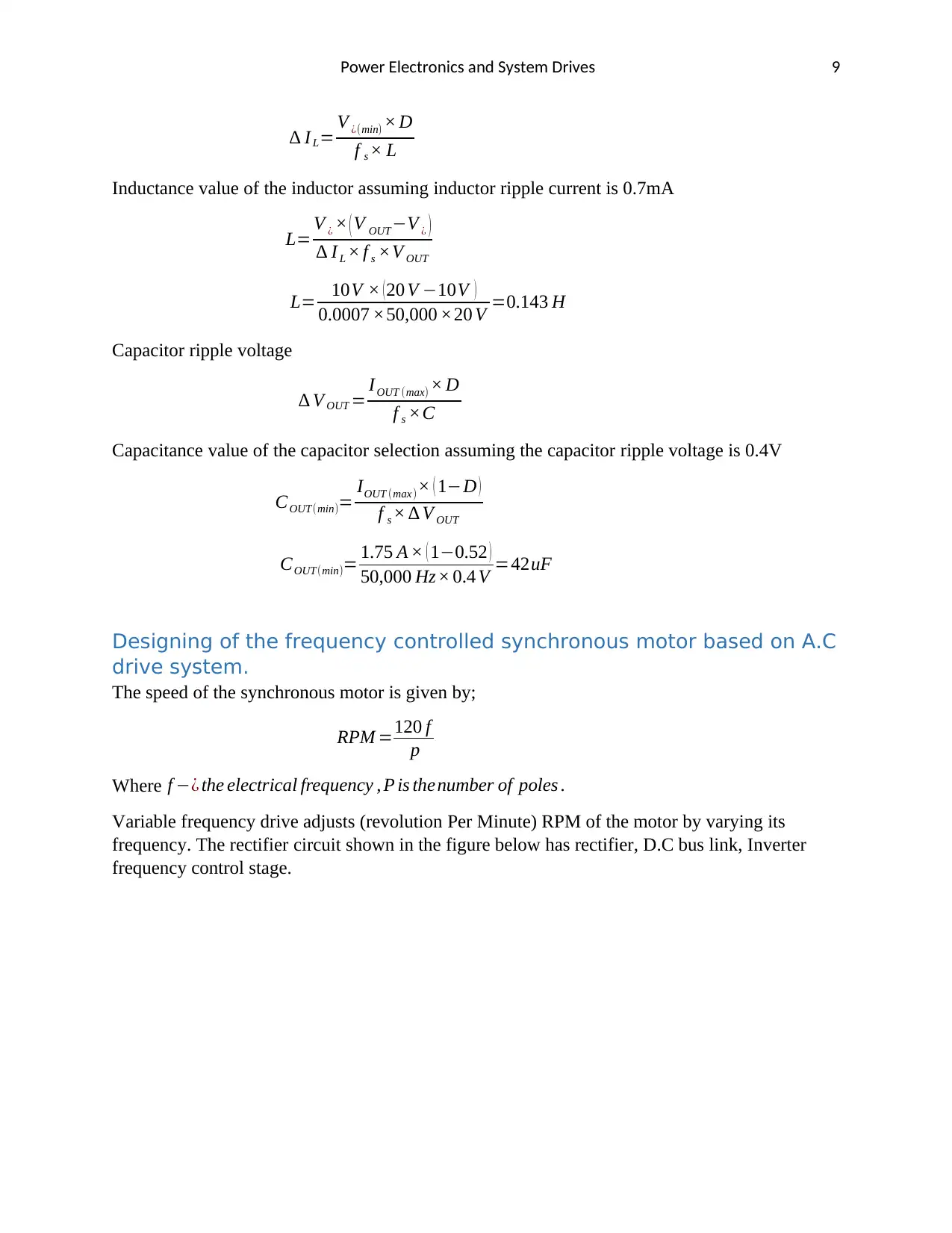
The boost converter in designed to step up input voltage to 20 V d.c output voltage.
Fig 7: Boost converter
The boost converter charger have the following parameters.
V ¿ ( min ) =10 V , V ¿ ( max ) =15 V , V OUT =20 V , I OUT ( min ) =1.5 A, f s=50 kHz
I OUT (max )=1.75 A
Duty cycle of the system is calculated by the expression below.
D=1−V ¿( Min)
V OUT
D=1− 12V
25 V =0.52
Inductor ripple current
Power Electronics and System Drives 9
∆ IL= V ¿(min) × D
f s × L
Inductance value of the inductor assuming inductor ripple current is 0.7mA
L= V ¿ × ( V OUT−V ¿ )
∆ I L × f s ×V OUT
L= 10V × ( 20 V −10V )
0.0007 ×50,000 ×20 V =0.143 H
Capacitor ripple voltage
∆ V OUT = IOUT (max) × D
f s ×C
Capacitance value of the capacitor selection assuming the capacitor ripple voltage is 0.4V
COUT(min)= IOUT (max )× ( 1−D )
f s × ∆ V OUT
COUT(min)= 1.75 A × ( 1−0.52 )
50,000 Hz× 0.4 V =42uF
Designing of the frequency controlled synchronous motor based on A.C
drive system.
The speed of the synchronous motor is given by;
RPM =120 f
p
Where f −¿ the electrical frequency , P is thenumber of poles .
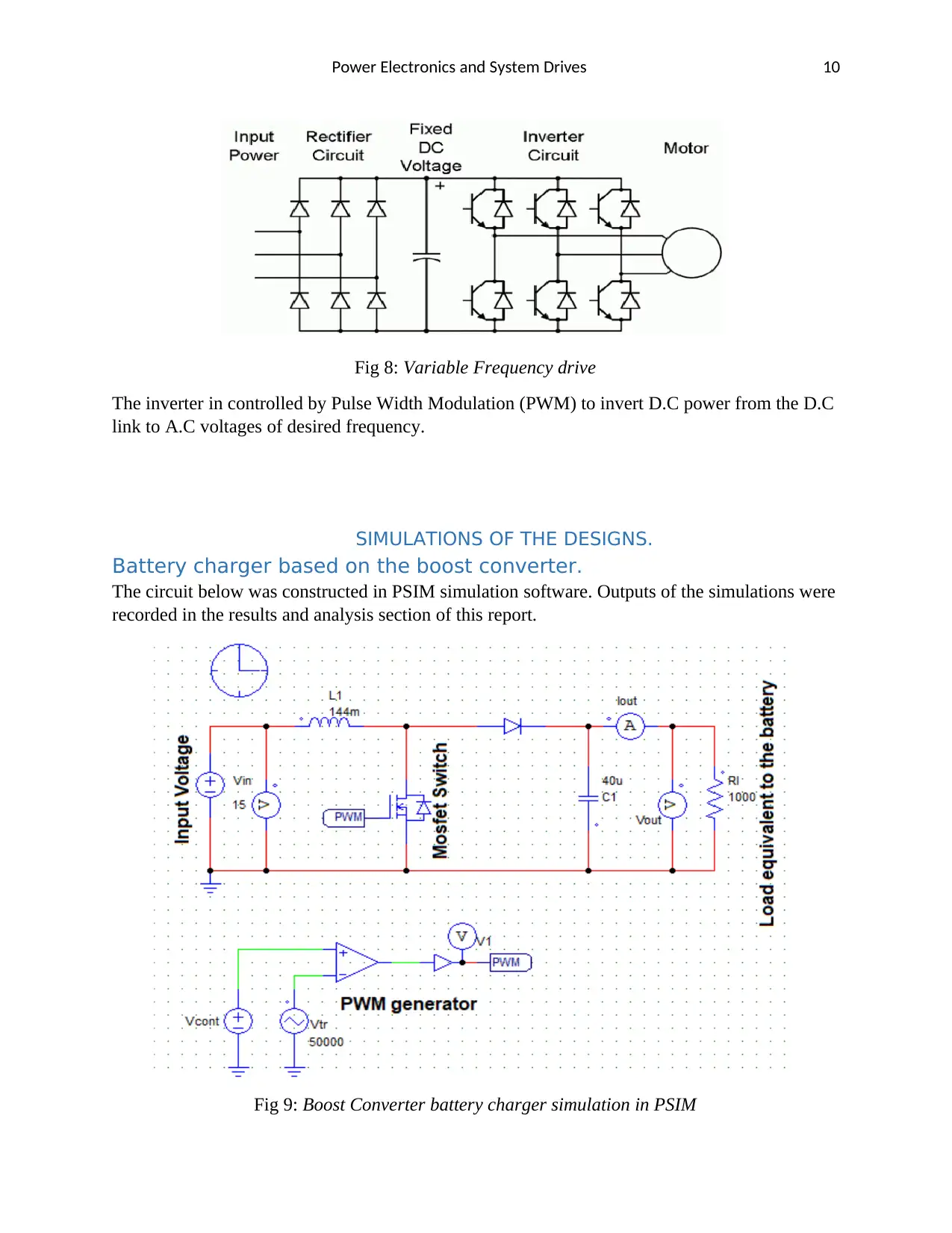
Variable frequency drive adjusts (revolution Per Minute) RPM of the motor by varying its
frequency. The rectifier circuit shown in the figure below has rectifier, D.C bus link, Inverter
frequency control stage.
⊘ This is a preview!⊘
Do you want full access?
Subscribe today to unlock all pages.

Trusted by 1+ million students worldwide
Power Electronics and System Drives 10
Fig 8: Variable Frequency drive
The inverter in controlled by Pulse Width Modulation (PWM) to invert D.C power from the D.C
link to A.C voltages of desired frequency.
SIMULATIONS OF THE DESIGNS.
Battery charger based on the boost converter.
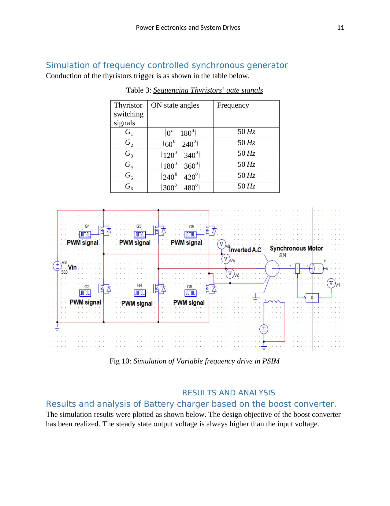
The circuit below was constructed in PSIM simulation software. Outputs of the simulations were
recorded in the results and analysis section of this report.
Fig 9: Boost Converter battery charger simulation in PSIM
Paraphrase This Document
Need a fresh take? Get an instant paraphrase of this document with our AI Paraphraser
Power Electronics and System Drives 11
Simulation of frequency controlled synchronous generator
Conduction of the thyristors trigger is as shown in the table below.
Table 3: Sequencing Thyristors’ gate signals
Thyristor
switching
signals
ON state angles Frequency
G1 ( 0o 1800 ) 50 Hz
G2 ( 600 2400 ) 50 Hz
G3 ( 1200 3400 ) 50 Hz
G4 ( 1800 3600 ) 50 Hz
G5 ( 2400 4200 ) 50 Hz
G6 ( 3000 4800 ) 50 Hz
Fig 10: Simulation of Variable frequency drive in PSIM
RESULTS AND ANALYSIS
Results and analysis of Battery charger based on the boost converter.
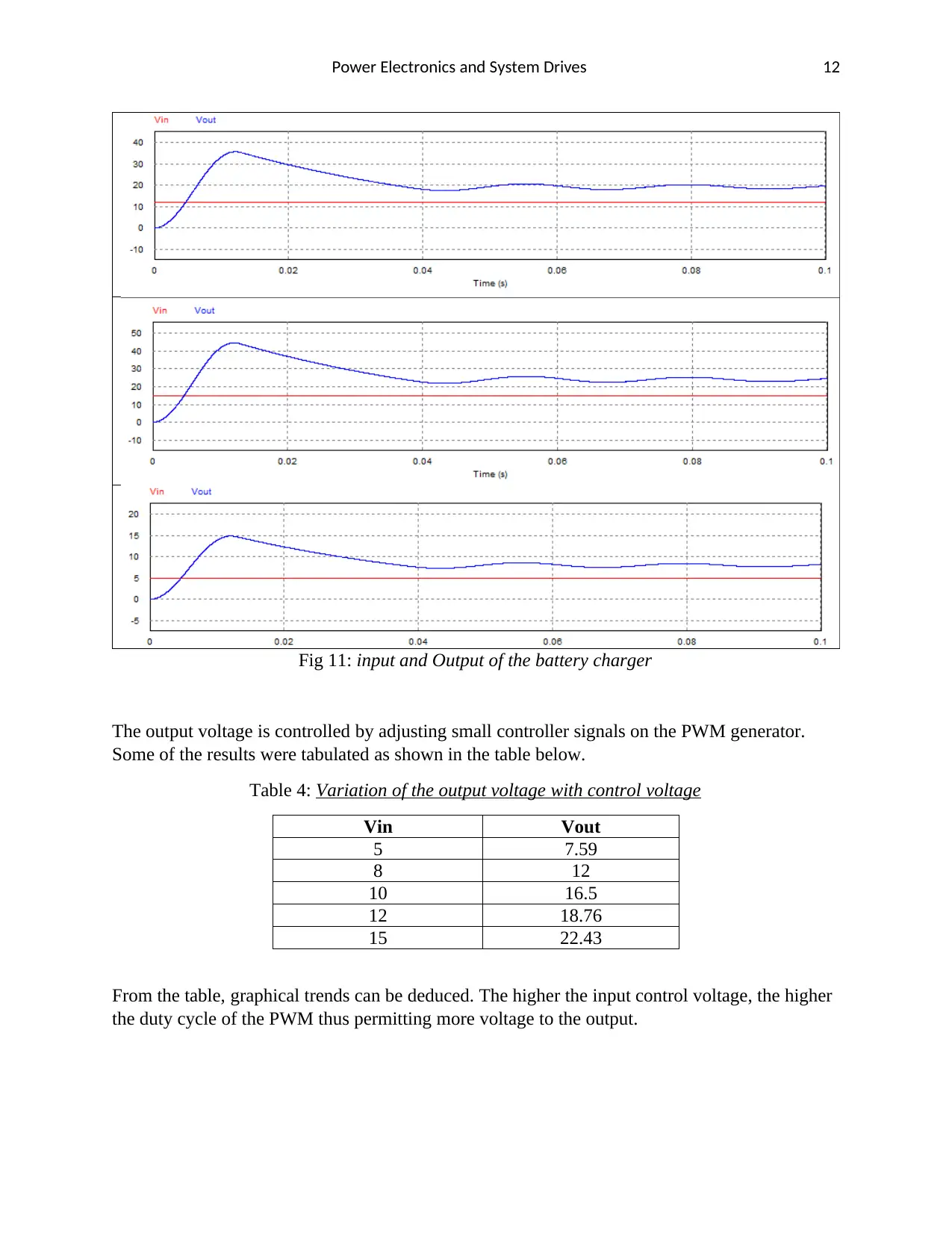
The simulation results were plotted as shown below. The design objective of the boost converter
has been realized. The steady state output voltage is always higher than the input voltage.
Power Electronics and System Drives 12
Fig 11: input and Output of the battery charger
The output voltage is controlled by adjusting small controller signals on the PWM generator.
Some of the results were tabulated as shown in the table below.
Table 4: Variation of the output voltage with control voltage
Vin Vout
5 7.59
8 12
10 16.5
12 18.76
15 22.43
From the table, graphical trends can be deduced. The higher the input control voltage, the higher
the duty cycle of the PWM thus permitting more voltage to the output.
⊘ This is a preview!⊘
Do you want full access?
Subscribe today to unlock all pages.

Trusted by 1+ million students worldwide
1 out of 16
Your All-in-One AI-Powered Toolkit for Academic Success.
+13062052269
info@desklib.com
Available 24*7 on WhatsApp / Email
![[object Object]](/_next/static/media/star-bottom.7253800d.svg)
Unlock your academic potential
Copyright © 2020–2025 A2Z Services. All Rights Reserved. Developed and managed by ZUCOL.

