CE 1.1 Power Management System Project Report, Bangalore
VerifiedAdded on 2023/06/08
|8
|1651
|129
Project
AI Summary
This project report details the design and implementation of a Power Management System (PMS) at BMS Evening College of Engineering, Bangalore. The project focuses on automating a distributed electrical system using a Programmable Logic Controller (PLC) with an S7-300 Series CPU and SCADA software. The objectives included reviewing efficient power management methods, proposing a suitable design, and evaluating the system's output. The student's responsibilities encompassed electrical maintenance, equipment installation, and design development. The project involved identifying and solving issues related to maximum load evaluation and EB failure in semi-auto mode. The student successfully designed a system capable of managing, controlling power, and providing automation, including high voltage switching and generator operation. Collaborative work and regular meetings with team members were crucial for project completion. The final system incorporates fault simulation, PLC control, and SCADA monitoring for effective power management.
CE 1.1 Project Information
Name of the project: Power Management System
Location of the project: BMS Evening College of Engineering, Basvanagudi,
Bangalore – 560 019
Project Duration: Please fill
Organization: BMS Evening College of Engineering, Basvanagudi, Bangalore
Role and Designation during the time: Team Member of the project
CE 1.2 Project Background
CE 1.2.1 Characteristics of the project
A Power Management System or PMS helps to take the charge for controlling any
particular electrical system. This power management system helps to make the electrical
system extremely safe and secured. When the consumption of power is much larger than the
capacity of power production, the technique of load shedding is significantly utilized for the
purpose of avoiding of blackouts. In this project, my aim was to provide automation for
distributed electrical system. Our system included Programmable Logic Controller or PLC
with an enhanced S7-300 Series PLC central unit CPU 315 - 2DP and associated digital input
& output modules, which directly interfaces field signals of 24V DC. I had even executed the
Communication from the PLC to the PC running SCADA by Profibus communication. I even
aided the set of monitoring as well as control functions. Hence, in the project, I have
significantly developed the compact and complete design of a power management system and
hence evaluated the efficiency of the desired outcome.
Paraphrase This Document
Need a fresh take? Get an instant paraphrase of this document with our AI Paraphraser
CE 1.2.2 Objectives developed for the project
During the project of Power Management System, the entire designing part required
higher constants that can easily increase the effectiveness and operation. I have even found
out the fact that the utilization of programmable logic controller can subsequently provide a
better efficiency. Thus, in the project my objective was to develop a design while providing a
better automation to the distributed electrical system that I have selected. Therefore, for
completing this project with higher efficiency as well as priority, I have successfully
developed the following objectives:
To review and analyze several methods of power management that is efficient.
To propose an appropriate design for the Power Management System.
To check the different forms of outputs in previous researches.
To review the output and check with the desired outcome.
To use SCADA station with higher version of computer and associated software of
WinCC.
To check whether there is a continuous flow of current to the load.
CE 1.2.3 My area of work
Before starting the work in this project, I have researched about the power
management system that helps to provide automation to any specific distribution electrical
system. The practical part of the project was started only after studying and reviewing the
past studies on the basis of power management system to understand and evaluate the
characteristics. My major area of work was simply to propose a compact design for the
system. I even had to follow all the standard operating processes for successfully
understanding the operations of electrical system. My other important areas of work were to
participate within the usage as well as advancement of the complete computerized and
digitalized management system.
CE 1.2.4 Project Group
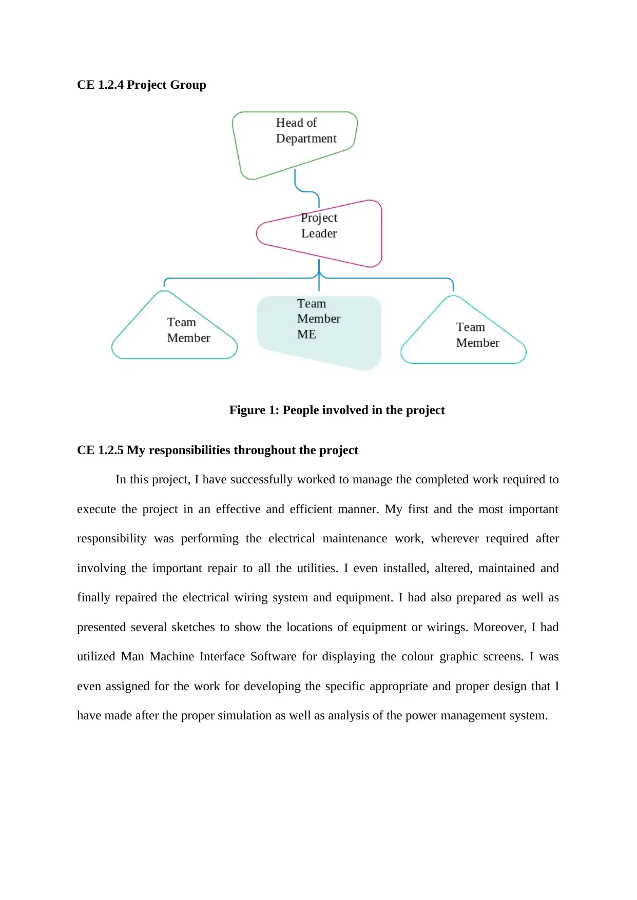
Figure 1: People involved in the project
CE 1.2.5 My responsibilities throughout the project
In this project, I have successfully worked to manage the completed work required to
execute the project in an effective and efficient manner. My first and the most important
responsibility was performing the electrical maintenance work, wherever required after
involving the important repair to all the utilities. I even installed, altered, maintained and
finally repaired the electrical wiring system and equipment. I had also prepared as well as
presented several sketches to show the locations of equipment or wirings. Moreover, I had
utilized Man Machine Interface Software for displaying the colour graphic screens. I was
even assigned for the work for developing the specific appropriate and proper design that I
have made after the proper simulation as well as analysis of the power management system.
⊘ This is a preview!⊘
Do you want full access?
Subscribe today to unlock all pages.

Trusted by 1+ million students worldwide
CE 1.3 Distinctive Activity
CE 1.3.1 Comprehending the Theory of Project
This particular project of Power Management System mainly focused on the
controlling of power during any type of abnormal situation and when decision making
becomes extremely difficult. These types of issues could be controlled by aiding a set of
monitoring and controlling functions. I have designed an advanced computerized energy
management system that comprised of SCADA or PLC software package to monitor, report
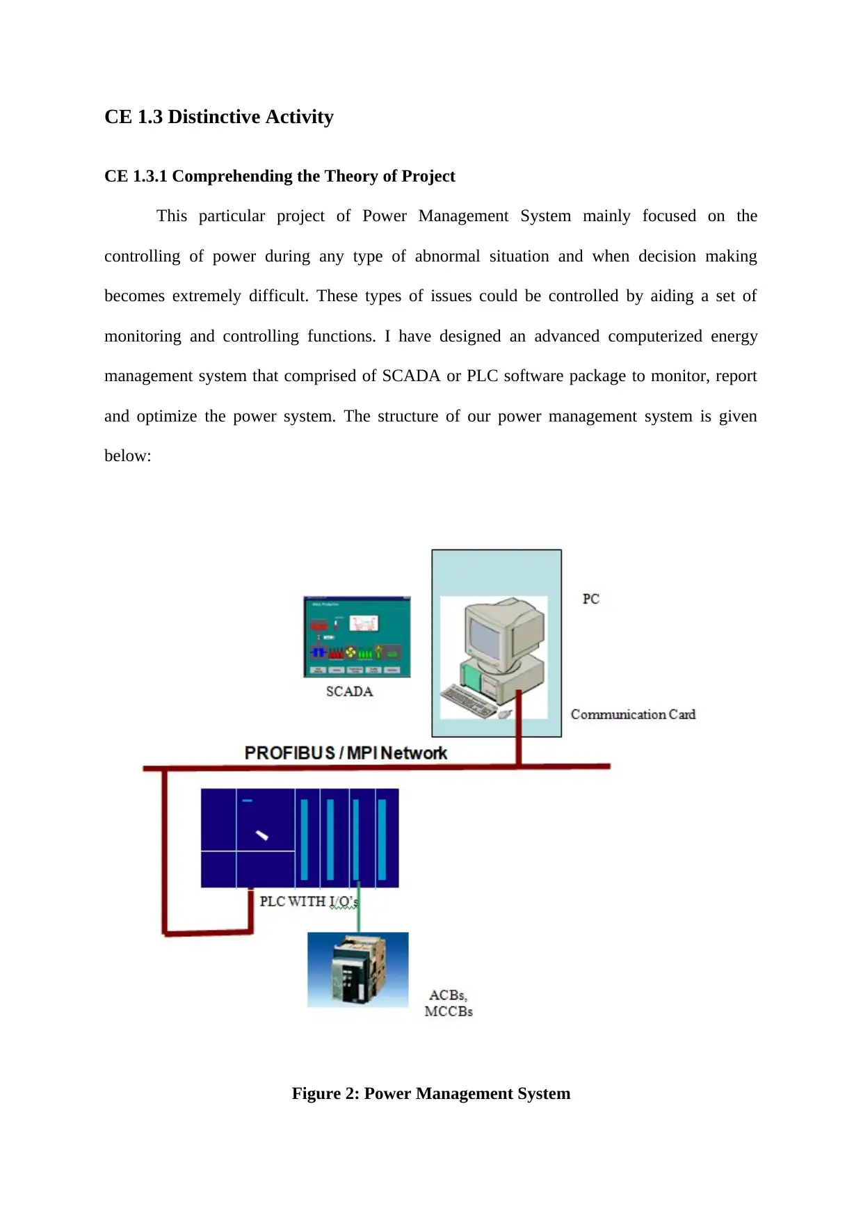
and optimize the power system. The structure of our power management system is given
below:
Figure 2: Power Management System
Paraphrase This Document
Need a fresh take? Get an instant paraphrase of this document with our AI Paraphraser
I have identified the fault stimulations in this project. There were two types of faults,
which were DG fault and EB fault. I have used Toggle switches of 5A/250 V as the mimic
panel and a specific PLC in my project. The control components of power management
system are power converter, moulded case circuit breaker or MCB for isolating the current,
C1 to C12 with both input and output ports C10 to C12 for spare.
CE 1.3.2 Engineering knowledge and skills applied in the project
The first skill that I have applied here is the circuit designing. I hold a good
understanding of the working procedures of circuits. The instrumentations and the proper
electrical measurements were the next significant skills applied in this project. I had also
tested the electric current and each and every component from reacting with each other. I
have also utilized several important programming languages to solve every equation and even
for circuit designing.
CE 1.3.3 Accomplishment and Task Performed
I had identified the various faults and specifications in LED Indication. The system
faults, Buss faults, DC supply, FORCE, RUN, STOP and MRES or memory reset were noted
by me.
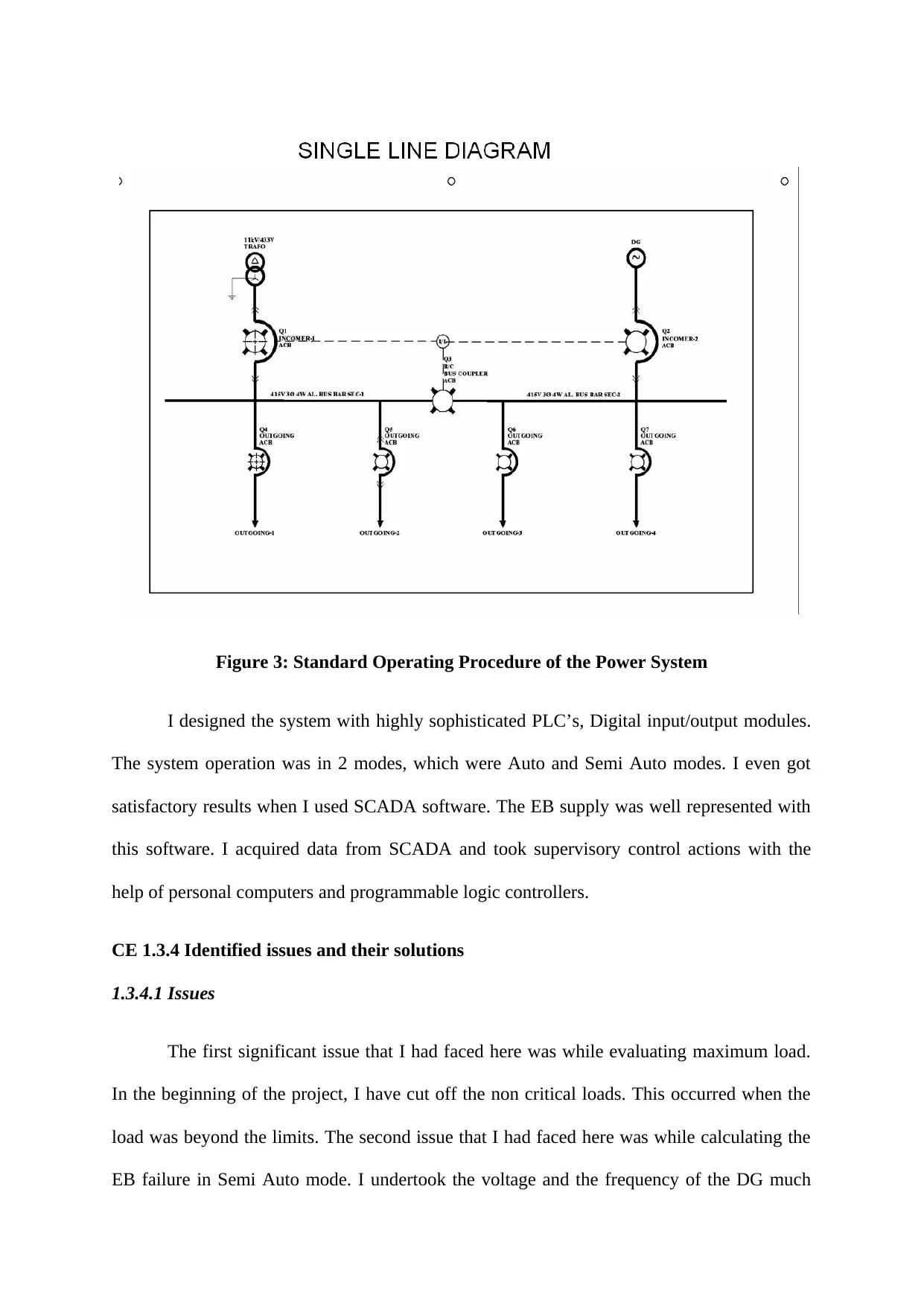
Figure 3: Standard Operating Procedure of the Power System
I designed the system with highly sophisticated PLC’s, Digital input/output modules.
The system operation was in 2 modes, which were Auto and Semi Auto modes. I even got
satisfactory results when I used SCADA software. The EB supply was well represented with
this software. I acquired data from SCADA and took supervisory control actions with the
help of personal computers and programmable logic controllers.
CE 1.3.4 Identified issues and their solutions
1.3.4.1 Issues
The first significant issue that I had faced here was while evaluating maximum load.
In the beginning of the project, I have cut off the non critical loads. This occurred when the
load was beyond the limits. The second issue that I had faced here was while calculating the
EB failure in Semi Auto mode. I undertook the voltage and the frequency of the DG much
⊘ This is a preview!⊘
Do you want full access?
Subscribe today to unlock all pages.

Trusted by 1+ million students worldwide
higher than the usual range and hence erroneous results were coming in the project. When the
system operation was not working properly, the results were not coming perfect and thus they
were completely erroneous in my project. I distinctly compared my experimental results with
the simulation and the theoretical results. Each and every above mentioned issue was to be
solved as early as possible.
1.3.4.2 Solutions
I provided some of the most relevant solutions to all the above mentioned issues,
which we had come across in this project of Power Management System. For the very first
issue of maximum demand, I gave the suggestion that we should use open bus coupler and
start our DG. I even fed the supply to the non critical loads, when they required supply. For
the second significant issue of EB failure in the semi auto mode, I finally checked for the
voltage and the frequency of our DG, with in the required permissible limits. These limits
were 380 V to 430 V and 48 Hz to 50 Hz. Moreover, I even closed the Bus coupler ACB
from SCADA PC by keeping Auto or Semi auto selector button in Semi auto mode and
subsequently ensured that the EB I/C must be in open condition.
CE 1.3.5 Plan to produce creative and innovative work
My plan was simply to produce the most creative and innovative work by perfectly
dividing our work. This kind of effective and efficient plan helped me in knowing and
identifying our errors and flaws and thus I was successful to remove each and every problem
within this particular project.
CE 1.3.6 Collaborative Work
We made sure that each and every team member is executing their duties or
responsibilities effectively and efficiently. I even arranged for regular meetings in our project
Paraphrase This Document
Need a fresh take? Get an instant paraphrase of this document with our AI Paraphraser
schedule to identify the loopholes. Moreover, this project was completed with the
collaborative work of our project team members.
CE 1.4 Project Review
CE 1.4.1 Project Overview
The entire project result helped me in designing a system that has the core capability
to change manage and control power and provide automation to electrical system. The higher
voltage switching was the main part in this project. I even operated the generators for
supporting the operations.
CE 1.4.2 My Contribution to work
In this project, I have performed higher voltage switching as well as operated
generators for the support of each and every operation at the transmission plant. I also had
planned for the electrical installations to reduce of wastage of material and then provided
proper access for future maintenance. I also took up the research part and then documented
the entire project report.
1 out of 8
Related Documents
Your All-in-One AI-Powered Toolkit for Academic Success.
+13062052269
info@desklib.com
Available 24*7 on WhatsApp / Email
![[object Object]](/_next/static/media/star-bottom.7253800d.svg)
Unlock your academic potential
Copyright © 2020–2026 A2Z Services. All Rights Reserved. Developed and managed by ZUCOL.


