Detailed Report on Power System Protection, Safety, and Earthing
VerifiedAdded on 2023/06/03
|11
|1893
|470
Report
AI Summary
This report provides a detailed overview of power system protection, focusing on feeder protection strategies, condition monitoring techniques for power equipment, and essential safety considerations. It explains the importance of earthing or grounding for safety, highlighting how it protects personnel from hazardous voltages by directing fault currents to the earth. The report also covers operating standards for generators connected to transmission systems and workplace safety practices, including induction and risk assessment to prevent electrical hazards. Key aspects include the use of switches, circuit breakers, automatic reclosers, and fuses for feeder protection, as well as online and offline methods for monitoring the condition of power cables and capacitors. Furthermore, the document emphasizes safety measures such as proper generator placement, fuel handling precautions, and the use of insulated tools to prevent electrical shocks and fire hazards. The document is available on Desklib, a platform that provides students with access to a wide range of study tools and solved assignments.

POWER PROTECTION
By Name
Course
Instructor
Institution
Location
Date
By Name
Course
Instructor
Institution
Location
Date
Paraphrase This Document
Need a fresh take? Get an instant paraphrase of this document with our AI Paraphraser
(a) Feeder protection
Feeder protection work on the principle that when there is an occurrence of fault on a feeder
itself then the fault is cleared by an upstream protection. The commonly addressed problems
emanate from the effect of over current and the Earth fault. Several equipment is required to
facilitate the protection of the distribution feeder. The most commonly used equipment includes
the following:
Switches-This is a circuit component that is used to connect and disconnect the circuits so as to
offer protection to the feeder .They is of different types
Disconnect Switch
This kind of the device serves to disconnect the devices of power when there are no loads.
Switches are devices or the circuit components that are used for changing the connections.
Sometimes they are used for making the circuits.
Circuit breakers
This is a circuit component that is used to interrupt the fault current.
Load break switch
This is a device that is designed specifically to break or to interrupt the load current.
Automatic Sectionaliser
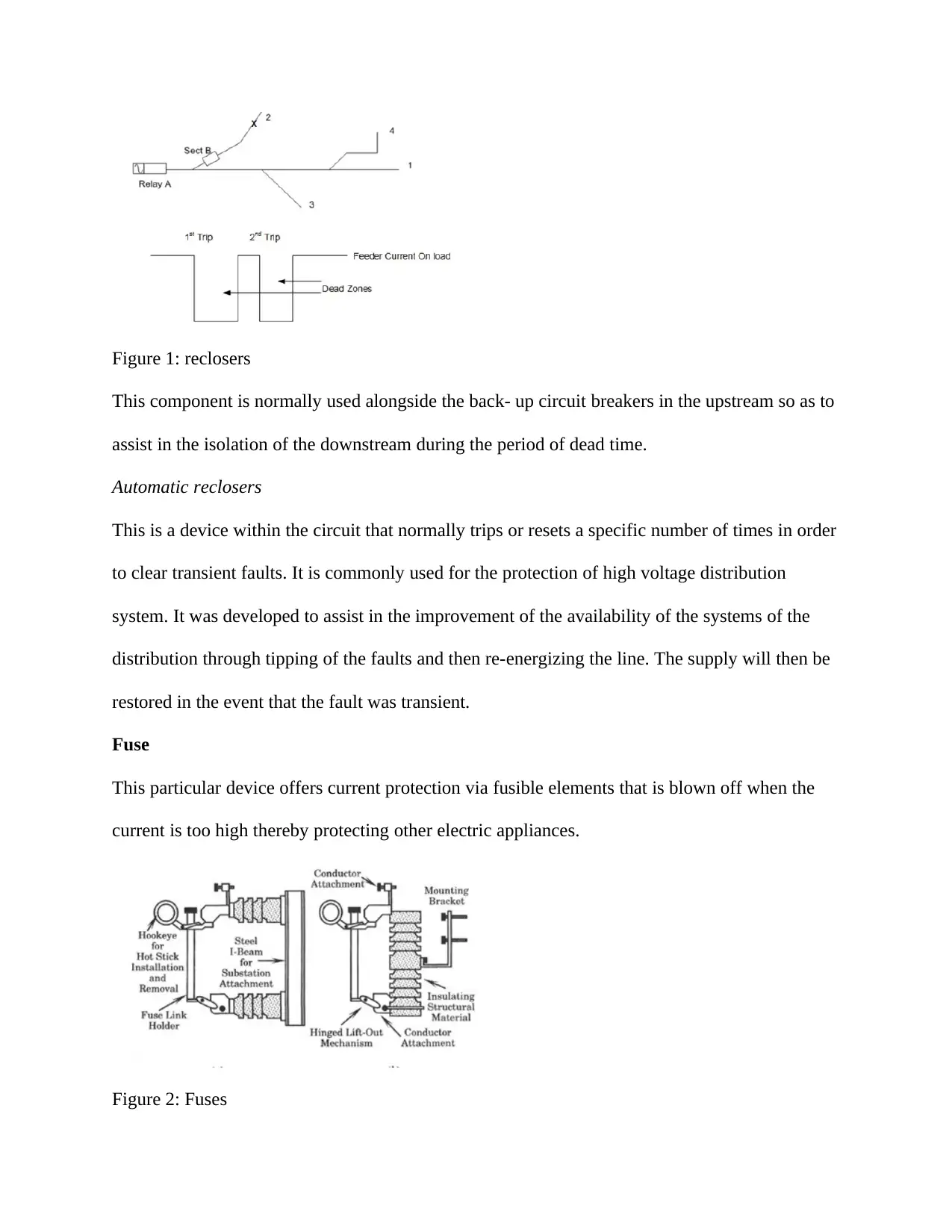
Figure 1: reclosers
This component is normally used alongside the back- up circuit breakers in the upstream so as to
assist in the isolation of the downstream during the period of dead time.
Automatic reclosers
This is a device within the circuit that normally trips or resets a specific number of times in order
to clear transient faults. It is commonly used for the protection of high voltage distribution
system. It was developed to assist in the improvement of the availability of the systems of the
distribution through tipping of the faults and then re-energizing the line. The supply will then be
restored in the event that the fault was transient.
Fuse
This particular device offers current protection via fusible elements that is blown off when the
current is too high thereby protecting other electric appliances.
Figure 2: Fuses
⊘ This is a preview!⊘
Do you want full access?
Subscribe today to unlock all pages.

Trusted by 1+ million students worldwide
(b) Condition monitoring for various power equipment’s
Condition monitoring and technologies of the diagnosis for the cable
The condition monitoring and technologies of the diagnosis for the power cables can be
classified can be classified into two categories. However, the online monitoring is known to be
having several advantages over the off-line methods[3]. The commonly used on-line methods of
monitoring include the distributed temperature sensors.
The sheath and on-line PD current monitoring. The detection of the temperature is very
important since it allows for the determination of the insulation and carrying capacity by
monitoring the temperature of the cables. The cable temperature is used in the determination of
the life of the cable as per the Arrhenius Law traditional methods of the temperature detection
was used to detect the temperature at specific points. The device could be installed at one point
along the wire. The results that were obtained were regarded local since it was not on the entire
cable[4].
Monitoring of the sheath current can assist in the reflection of insulation conditions of the cable.
The distributed sheath current normally assist in the recording of the short-circuit current the
point of the instant of the cable fault and the time when the actuation process of the system
responds.
The large current and power consumptions in the big cities have made it very challenging to have
the extraction of the sheath current. One of the key challenges that are associated with the PD
monitoring is the accurate coupling of the cable voltage to the system for the test[5].
Condition monitoring and diagnosis for the power capacitor
Paraphrase This Document
Need a fresh take? Get an instant paraphrase of this document with our AI Paraphraser
The power factor normally plays a major role in the improvement of the voltage quality, power
factor, transmission ability and system stability. Considering that such equipment’s are normally
subjected to very long operating voltage, working conditions, and short term over voltage, the
power capacitor faults that include high temperature rise, degradation of the insulation system
and abnormal noise are common[6]. The oil leakage may occur and this can possibly lead to
unsafe conditions of the operation. It is therefore very important to monitor the operating
conditions of the power capacitor.
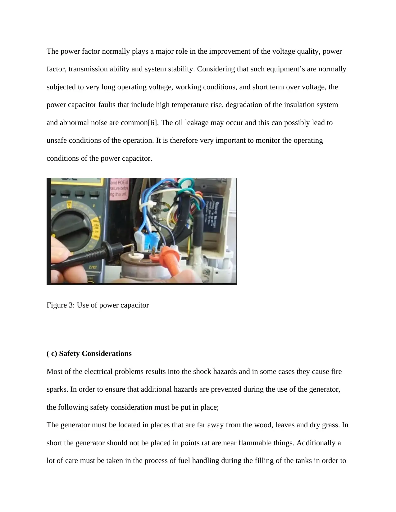
Figure 3: Use of power capacitor
( c) Safety Considerations
Most of the electrical problems results into the shock hazards and in some cases they cause fire
sparks. In order to ensure that additional hazards are prevented during the use of the generator,
the following safety consideration must be put in place;
The generator must be located in places that are far away from the wood, leaves and dry grass. In
short the generator should not be placed in points rat are near flammable things. Additionally a
lot of care must be taken in the process of fuel handling during the filling of the tanks in order to
prevent the spills. The oiling or fuelling should not be done during the operation. The engine
should be allowed to cool down completely before addition of the fuel.
There should be no smoking near the location of the generator[7].
(d) I explain how Earthling or grounding is important for safety
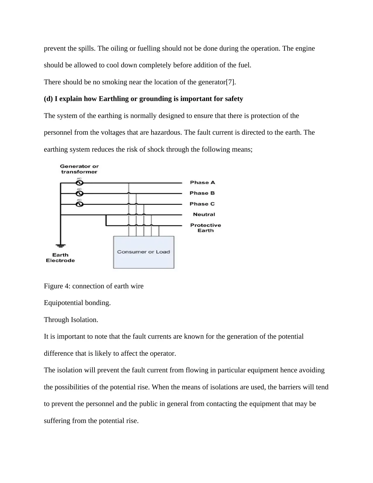
The system of the earthing is normally designed to ensure that there is protection of the
personnel from the voltages that are hazardous. The fault current is directed to the earth. The
earthing system reduces the risk of shock through the following means;
Figure 4: connection of earth wire
Equipotential bonding.
Through Isolation.
It is important to note that the fault currents are known for the generation of the potential
difference that is likely to affect the operator.
The isolation will prevent the fault current from flowing in particular equipment hence avoiding
the possibilities of the potential rise. When the means of isolations are used, the barriers will tend
to prevent the personnel and the public in general from contacting the equipment that may be
suffering from the potential rise.
⊘ This is a preview!⊘
Do you want full access?
Subscribe today to unlock all pages.

Trusted by 1+ million students worldwide
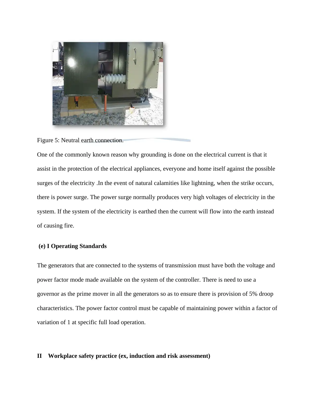
Figure 5: Neutral earth connection.
One of the commonly known reason why grounding is done on the electrical current is that it
assist in the protection of the electrical appliances, everyone and home itself against the possible
surges of the electricity .In the event of natural calamities like lightning, when the strike occurs,
there is power surge. The power surge normally produces very high voltages of electricity in the
system. If the system of the electricity is earthed then the current will flow into the earth instead
of causing fire.
(e) I Operating Standards
The generators that are connected to the systems of transmission must have both the voltage and
power factor mode made available on the system of the controller. There is need to use a
governor as the prime mover in all the generators so as to ensure there is provision of 5% droop
characteristics. The power factor control must be capable of maintaining power within a factor of
variation of 1 at specific full load operation.
II Workplace safety practice (ex, induction and risk assessment)
Paraphrase This Document
Need a fresh take? Get an instant paraphrase of this document with our AI Paraphraser
Avoid water at all the times when working with the electricity. Never touch or repair any
component of the electrical equipment with the wet hands since it is known to increase the
conductivity of the electric current.
Equipment’s that have got frayed cords should never be used. This includes the equipment’s with
the damaged insulation or the broken plugs.
Always ensure that the mains are turned off when working on the receptacle. This practice
should include putting up the sign on the service panel so as to ensure that no one turns on the
mains by accident
Insulating tools should be used always when working on electricity.
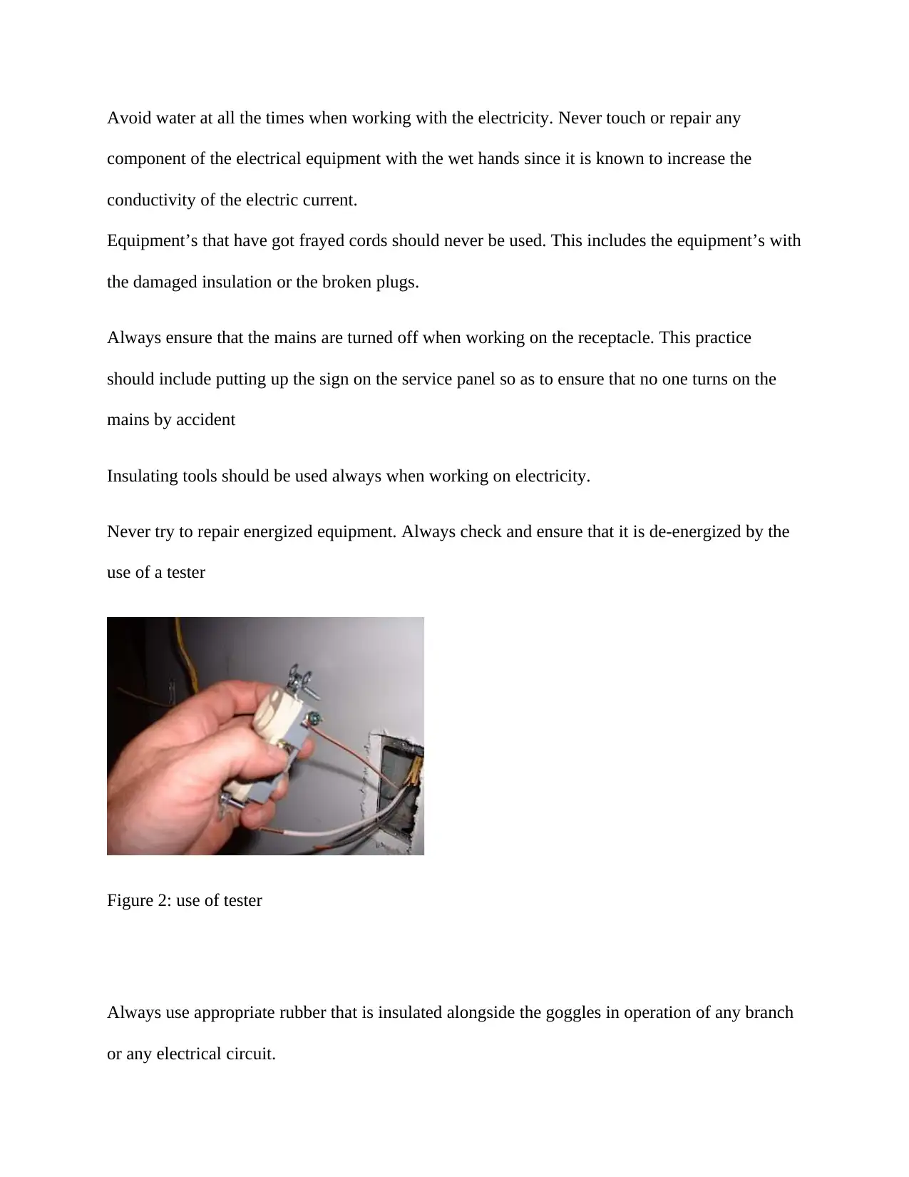
Never try to repair energized equipment. Always check and ensure that it is de-energized by the
use of a tester
Figure 2: use of tester
Always use appropriate rubber that is insulated alongside the goggles in operation of any branch
or any electrical circuit.

Never use a ladder that is made of steel when working on any receptacle at a height. This is
because there is possibility of electric surge passing through the operator
Always ensure that the wire coding o the country is known[9].
Always be observant on the signs that include Shock Risks since electrical hazards include
exposed energized parts and also the unguarded equipment’s of electricity that usually becomes
energized unexpectedly.
References
⊘ This is a preview!⊘
Do you want full access?
Subscribe today to unlock all pages.

Trusted by 1+ million students worldwide

[1]Boss, M.J. and Day, D., 2014. Circuit Disconnects, On/Off Switches, and OSHA.
In Electrical Safety (pp. 132-145). CRC Press.
[2]Boss, M.J. and Day, D., 2014. Grounding. In Electrical Safety(pp. 146-173). CRC Press.
[3]Boss, M.J. and Nicoll, G., 2014. Electrical testing. In Electrical Safety (pp. 236-263). CRC
Press.
[4]Boss, R. and Boss, M.J., 2014. Electromagnetic Shielded Equipment, Instrumentation, and
Facilities, Part One. In Electrical Safety (pp. 264-289). CRC Press.
[5]Freschi, F., Mitolo, M. and Tommasini, R., 2014, October. Electrical safety of aeronautical
ground lighting systems. In 2014 IEEE Industry Application Society Annual Meeting (pp. 1-7).
IEEE.
[6]Kemper, G.M., Vilcheck, W.S. and Durocher, D.B., 2014. The journey of an enterprise in a
process industry toward improved electrical workplace safety. IEEE Transactions on Industry
Applications, 50(5), pp.3072-3078.
[7]Lademann, J., Ulrich, C., Patzelt, A., Richter, H., Kluschke, F., Klebes, M., Lademann, O.,
Kramer, A., Weltmann, K.D. and Lange-Asschenfeldt, B., 2013. Risk assessment of the
application of tissue-tolerable plasma on human skin. Clinical Plasma Medicine, 1(1), pp.5-10.
[8]Nicoll, G., Boss, M.J., Tajali, R. and Zweifel, R., 2014. Arc Flash, Personal Protective
Equipment, and Classified Locations. In Electrical Safety (pp. 214-235). CRC Press.
[8]Paul, D., Peterson, K. and Chavdarian, P.R., 2014. Designing cold ironing power systems:
electrical safety during ship berthing. IEEE Industry Applications Magazine, 20(3), pp.24-32.
Paraphrase This Document
Need a fresh take? Get an instant paraphrase of this document with our AI Paraphraser

[9]Roberts, D., 2015, January. Risk assessment and your electrical safety program. In Electrical
Safety Workshop (ESW), 2015 IEEE IAS (pp. 1-6). IEEE.
Safety Workshop (ESW), 2015 IEEE IAS (pp. 1-6). IEEE.
1 out of 11
Related Documents
Your All-in-One AI-Powered Toolkit for Academic Success.
+13062052269
info@desklib.com
Available 24*7 on WhatsApp / Email
![[object Object]](/_next/static/media/star-bottom.7253800d.svg)
Unlock your academic potential
Copyright © 2020–2025 A2Z Services. All Rights Reserved. Developed and managed by ZUCOL.


