Power Supply Circuit
Added on 2023-03-23
4 Pages525 Words20 Views
Power Supply Circuit:
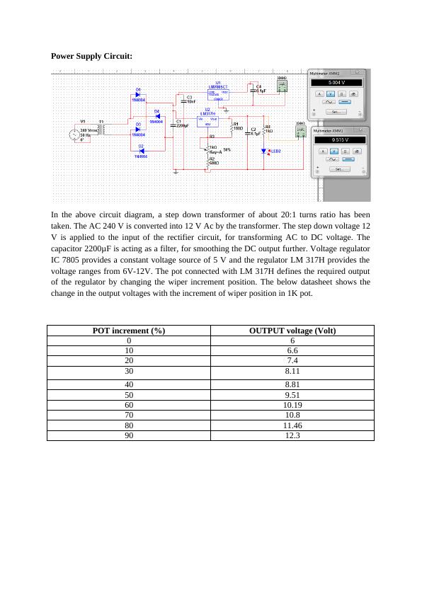
In the above circuit diagram, a step down transformer of about 20:1 turns ratio has been
taken. The AC 240 V is converted into 12 V Ac by the transformer. The step down voltage 12
V is applied to the input of the rectifier circuit, for transforming AC to DC voltage. The
capacitor 2200μF is acting as a filter, for smoothing the DC output further. Voltage regulator
IC 7805 provides a constant voltage source of 5 V and the regulator LM 317H provides the
voltage ranges from 6V-12V. The pot connected with LM 317H defines the required output
of the regulator by changing the wiper increment position. The below datasheet shows the
change in the output voltages with the increment of wiper position in 1K pot.
POT increment (%) OUTPUT voltage (Volt)
0 6
10 6.6
20 7.4
30 8.11
40 8.81
50 9.51
60 10.19
70 10.8
80 11.46
90 12.3
Decade Sequencer Circuit:
555Timmer:
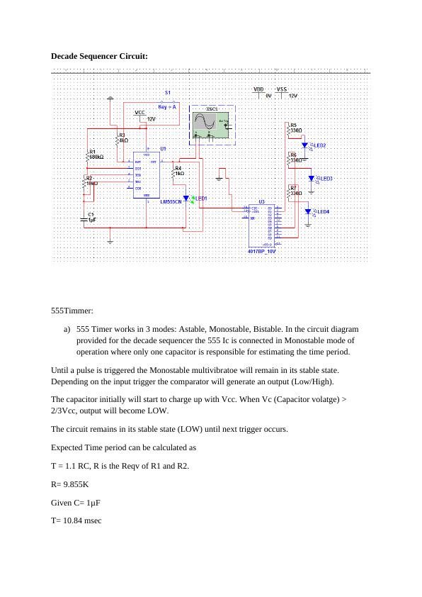
a) 555 Timer works in 3 modes: Astable, Monostable, Bistable. In the circuit diagram
provided for the decade sequencer the 555 Ic is connected in Monostable mode of
operation where only one capacitor is responsible for estimating the time period.
Until a pulse is triggered the Monostable multivibratoe will remain in its stable state.
Depending on the input trigger the comparator will generate an output (Low/High).
The capacitor initially will start to charge up with Vcc. When Vc (Capacitor volatge) >
2/3Vcc, output will become LOW.
The circuit remains in its stable state (LOW) until next trigger occurs.
Expected Time period can be calculated as
T = 1.1 RC, R is the Reqv of R1 and R2.
R= 9.855K
Given C= 1μF
T= 10.84 msec
555Timmer:
a) 555 Timer works in 3 modes: Astable, Monostable, Bistable. In the circuit diagram
provided for the decade sequencer the 555 Ic is connected in Monostable mode of
operation where only one capacitor is responsible for estimating the time period.
Until a pulse is triggered the Monostable multivibratoe will remain in its stable state.
Depending on the input trigger the comparator will generate an output (Low/High).
The capacitor initially will start to charge up with Vcc. When Vc (Capacitor volatge) >
2/3Vcc, output will become LOW.
The circuit remains in its stable state (LOW) until next trigger occurs.
Expected Time period can be calculated as
T = 1.1 RC, R is the Reqv of R1 and R2.
R= 9.855K
Given C= 1μF
T= 10.84 msec
End of preview
Want to access all the pages? Upload your documents or become a member.