Power System Analysis: Transmission Line Parameters and Stability
VerifiedAdded on 2023/05/28
|16
|1740
|475
Report
AI Summary
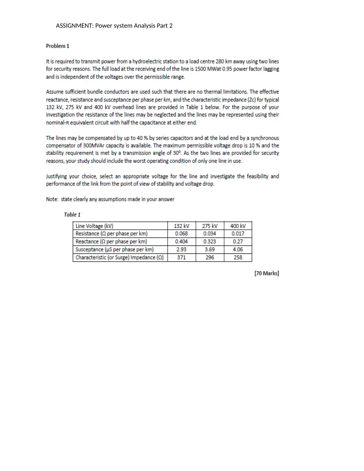
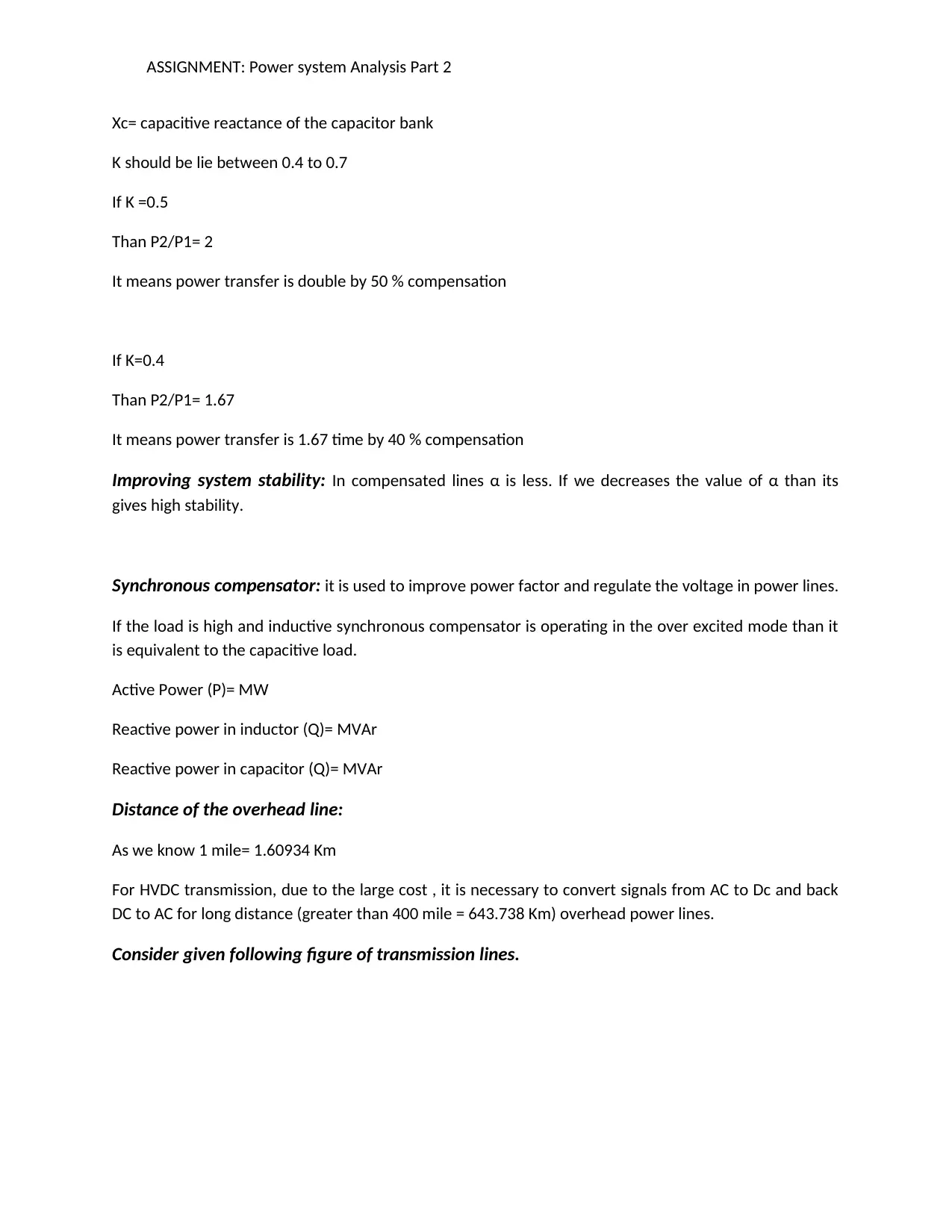
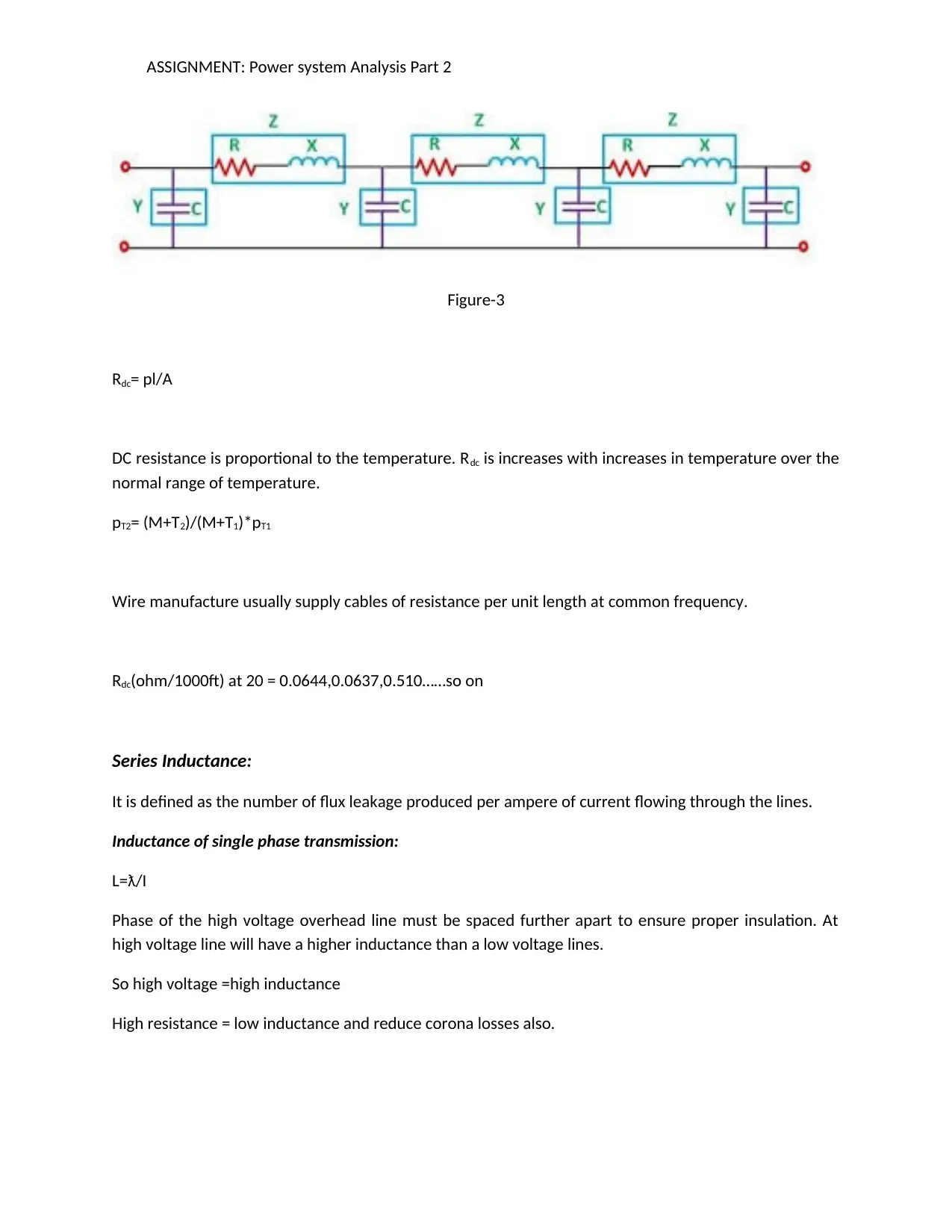
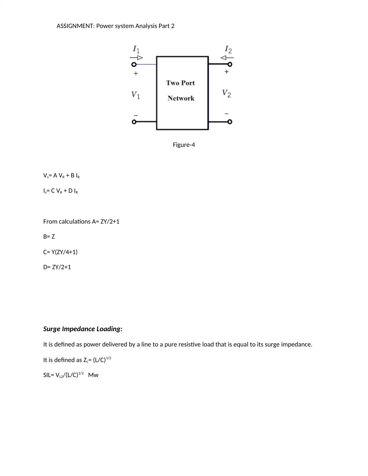
This report provides a comprehensive analysis of power systems, focusing on transmission line parameters, HVDC transmission, and system stability. It examines the impact of distance, voltage, and various line parameters on transmission efficiency. The report also discusses the role of series and synchronous compensation in improving system voltage and stability. Furthermore, it includes a fault analysis and calculations for interrupting and making capacity of circuit breakers. The analysis concludes with the selection of an appropriate voltage level for a given transmission distance and load, emphasizing the importance of minimizing energy loss and improving overall system performance. Desklib offers a wealth of resources, including solved assignments and past papers, to aid students in mastering these complex concepts.

1 out of 16
Your All-in-One AI-Powered Toolkit for Academic Success.
+13062052269
info@desklib.com
Available 24*7 on WhatsApp / Email
![[object Object]](/_next/static/media/star-bottom.7253800d.svg)
Copyright © 2020–2026 A2Z Services. All Rights Reserved. Developed and managed by ZUCOL.