logo

Power System Studies: Fault Analysis using Simulation Tool

Design the network, divide it in zones and draft the protection scheme for the draft network.

13 Pages1359 Words212 Views
   

Added on  2023-06-07

About This Document

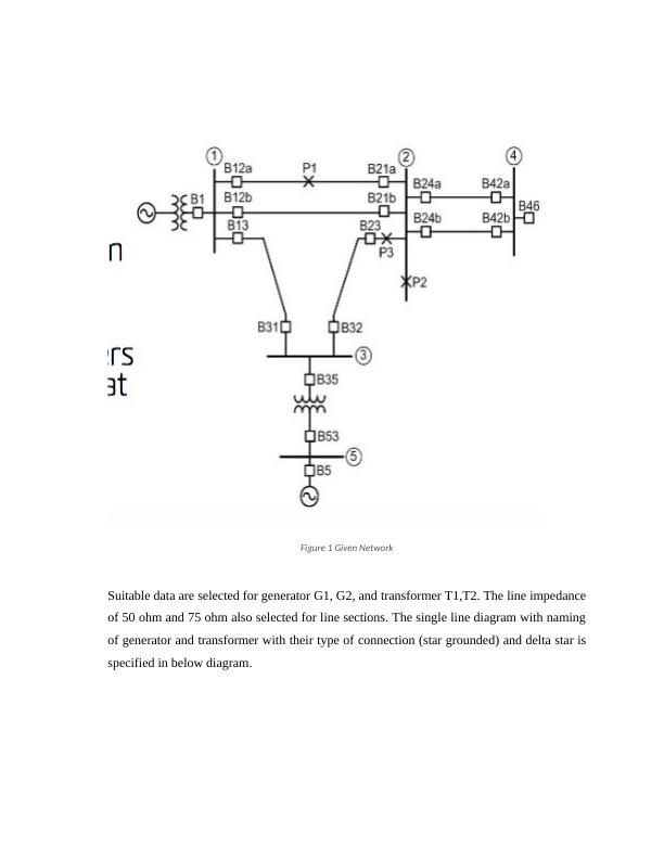
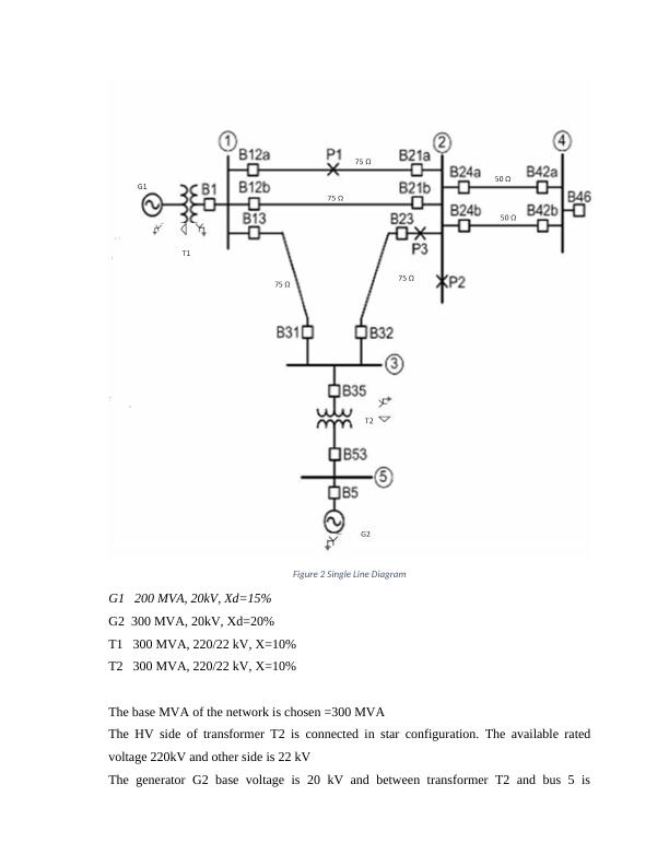
This experiment focuses on fault analysis in power systems using simulation tools like MATLAB, PsCAD, ETAP, EMTP, PSS etc. It covers the importance of relay setting and impedance calculation. The experiment analyzes fault currents for different fault points in the network. The network diagram is provided with suitable data for generator and transformer. The per unit impedance of the network components is calculated and the impedance diagram is drawn. The experiment also covers the calculation of fault current for different fault points in the network.

Power System Studies: Fault Analysis using Simulation Tool

Design the network, divide it in zones and draft the protection scheme for the draft network.

   Added on 2023-06-07

ShareRelated Documents
Unit name:
Title of experiment:
Date:
Student ID:
Student name:
Power System Studies: Fault Analysis using Simulation Tool_1
Solution A: The simulation tool plays important role for the power system studies. The
designing of power system involves lots of Data and their processing need to be done
within fraction of time with high accuracy indeed. Tools like MATLAB, PsCAD, ETAP,
EMTP, PSS etc. very important and useful tool for the power system protection studies.
The setting of relay can be done with the software simulation, setting 2,3 or 10 relay can be
done on paper with hand calculation but when interconnected power system need to be
studied the computer simulation plays important role. Relay setting task need so much
attention since it involves with the protection of power system, CT ratio, CB rating, fuse
rating and the impedance of network are key parameter need to be considered.
Solution B: For the given network below data are not provided so with the assumption of
suitable data related to the given network are assumed. Since long line network is assumed
line voltage and line impedance are chosen according to 220 kV line data with total
impedance rather than specifying the line length.
Power System Studies: Fault Analysis using Simulation Tool_2
Figure 1 Given Network
Suitable data are selected for generator G1, G2, and transformer T1,T2. The line impedance
of 50 ohm and 75 ohm also selected for line sections. The single line diagram with naming
of generator and transformer with their type of connection (star grounded) and delta star is
specified in below diagram.
Power System Studies: Fault Analysis using Simulation Tool_3
Figure 2 Single Line Diagram
G1 200 MVA, 20kV, Xd=15%
G2 300 MVA, 20kV, Xd=20%
T1 300 MVA, 220/22 kV, X=10%
T2 300 MVA, 220/22 kV, X=10%
The base MVA of the network is chosen =300 MVA
The HV side of transformer T2 is connected in star configuration. The available rated
voltage 220kV and other side is 22 kV
The generator G2 base voltage is 20 kV and between transformer T2 and bus 5 is
Power System Studies: Fault Analysis using Simulation Tool_4

End of preview

Want to access all the pages? Upload your documents or become a member.

Related Documents
Impedance and Power Analysis
|17
|2977
|254

Introduction to Power System Analysis
|13
|525
|284