Power Transmission Design: Friction Clutch, Gear Train, and Gearbox
VerifiedAdded on 2023/01/11
|9
|1381
|33
Practical Assignment
AI Summary
This document presents a comprehensive solution to a power transmission design assignment, addressing three key tasks. Task 1 focuses on designing a friction clutch and drive belt system for a Perkins diesel engine connected to an electrical generator, including calculations for belt length, number of belts, and clutch plate requirements. Task 2 analyzes a compound gear train with five gears, determining output speed, output power, and gearbox holding torque. Finally, Task 3 delves into an epicyclic speed reduction gearbox, calculating the number of annulus teeth, gear ratios, output speed, nominal torque, and holding torque, providing a detailed analysis of the system's performance. The assignment incorporates relevant formulas, calculations, and references to support the design and analysis of these power transmission components.
1GEARS POWER TRANSMISSION
POWER TRANSMISSION
Name of class
Professor
Name of School
City and State
Date
POWER TRANSMISSION
Name of class
Professor
Name of School
City and State
Date
Paraphrase This Document
Need a fresh take? Get an instant paraphrase of this document with our AI Paraphraser
2GEARS POWER TRANSMISSION
Task 1
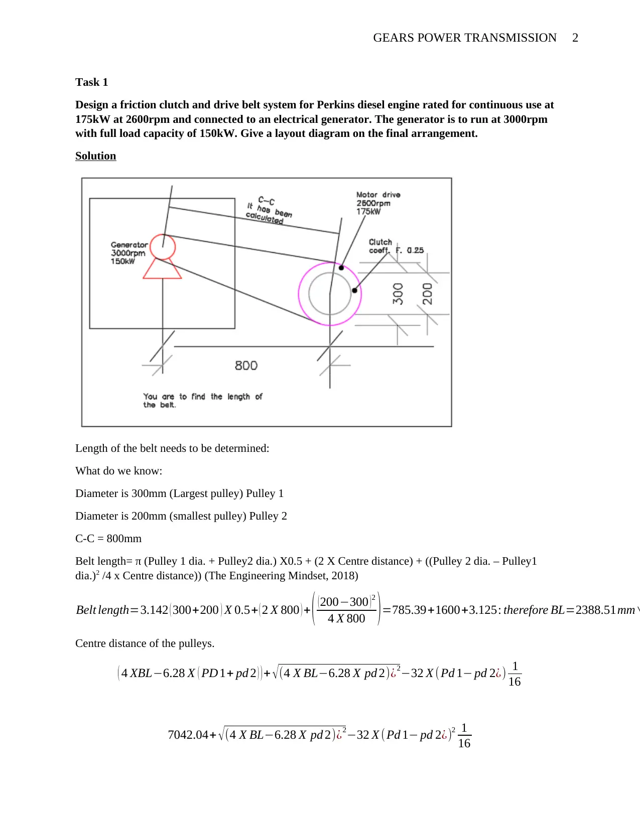
Design a friction clutch and drive belt system for Perkins diesel engine rated for continuous use at
175kW at 2600rpm and connected to an electrical generator. The generator is to run at 3000rpm
with full load capacity of 150kW. Give a layout diagram on the final arrangement.
Solution
Length of the belt needs to be determined:
What do we know:
Diameter is 300mm (Largest pulley) Pulley 1
Diameter is 200mm (smallest pulley) Pulley 2
C-C = 800mm
Belt length= π (Pulley 1 dia. + Pulley2 dia.) X0.5 + (2 X Centre distance) + ((Pulley 2 dia. – Pulley1
dia.)2 /4 x Centre distance)) (The Engineering Mindset, 2018)
Belt length=3.142 ( 300+200 ) X 0.5+ ( 2 X 800 ) + ( (200−300 )2
4 X 800 )=785.39+1600+3.125: therefore BL=2388.51mm∨
Centre distance of the pulleys.
( 4 XBL−6.28 X ( PD 1+ pd 2 ) ) + √ (4 X BL−6.28 X pd 2)¿2−32 X ( Pd 1− pd 2¿) 1
16
7042.04+ √ (4 X BL−6.28 X pd 2)¿2−32 X ( Pd 1− pd 2¿)2 1
16
3GEARS POWER TRANSMISSION
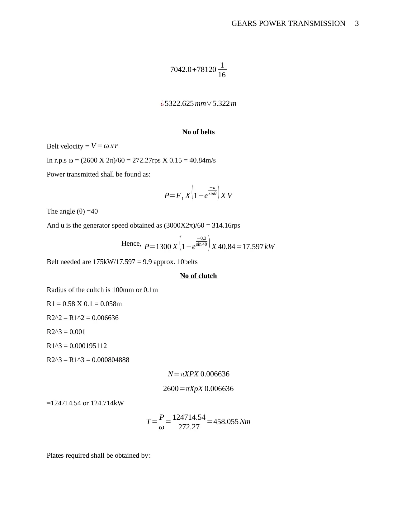
7042.0+78120 1
16
¿ 5322.625 mm∨5.322 m
No of belts
Belt velocity = V =ω x r
In r.p.s ω = (2600 X 2π)/60 = 272.27rps X 0.15 = 40.84m/s
Power transmitted shall be found as:
P=F1 X (1−e
−u
sinθ ) X V
The angle (θ) =40
And u is the generator speed obtained as (3000X2π)/60 = 314.16rps
Hence, P=1300 X (1−e
−0.3
sin 40 ) X 40.84=17.597 kW
Belt needed are 175kW/17.597 = 9.9 approx. 10belts
No of clutch
Radius of the cultch is 100mm or 0.1m
R1 = 0.58 X 0.1 = 0.058m
R2^2 – R1^2 = 0.006636
R2^3 = 0.001
R1^3 = 0.000195112
R2^3 – R1^3 = 0.000804888
N=πXPX 0.006636
2600=πXpX 0.006636
=124714.54 or 124.714kW
T = P
ω = 124714.54
272.27 =458.055 Nm
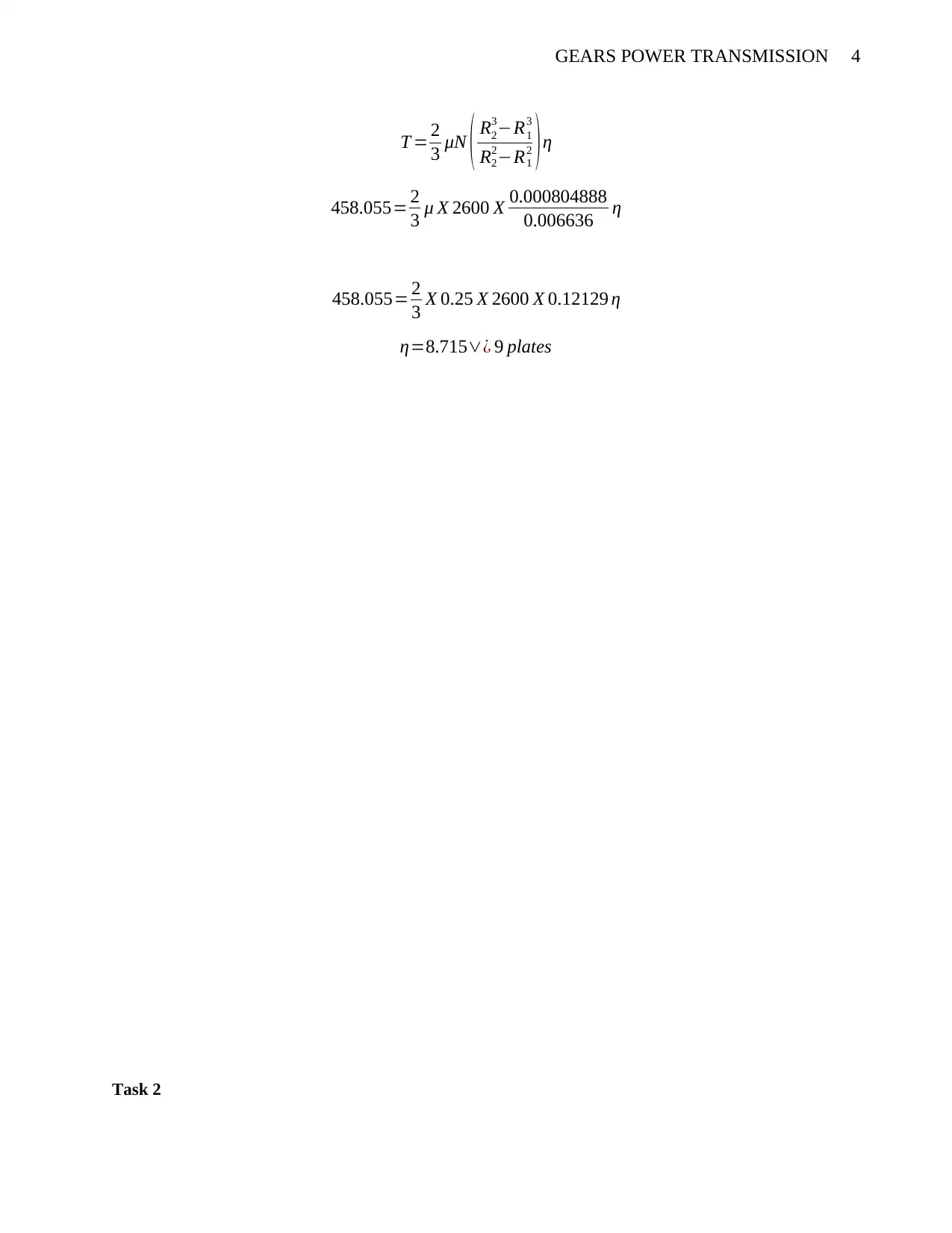
Plates required shall be obtained by:
⊘ This is a preview!⊘
Do you want full access?
Subscribe today to unlock all pages.

Trusted by 1+ million students worldwide
4GEARS POWER TRANSMISSION
T = 2
3 μN ( R2
3−R1
3
R2
2−R1
2 )η
458.055= 2
3 μ X 2600 X 0.000804888
0.006636 η
458.055= 2
3 X 0.25 X 2600 X 0.12129 η
η=8.715∨¿ 9 plates
Task 2
T = 2
3 μN ( R2
3−R1
3
R2
2−R1
2 )η
458.055= 2
3 μ X 2600 X 0.000804888
0.006636 η
458.055= 2
3 X 0.25 X 2600 X 0.12129 η
η=8.715∨¿ 9 plates
Task 2
Paraphrase This Document
Need a fresh take? Get an instant paraphrase of this document with our AI Paraphraser
5GEARS POWER TRANSMISSION
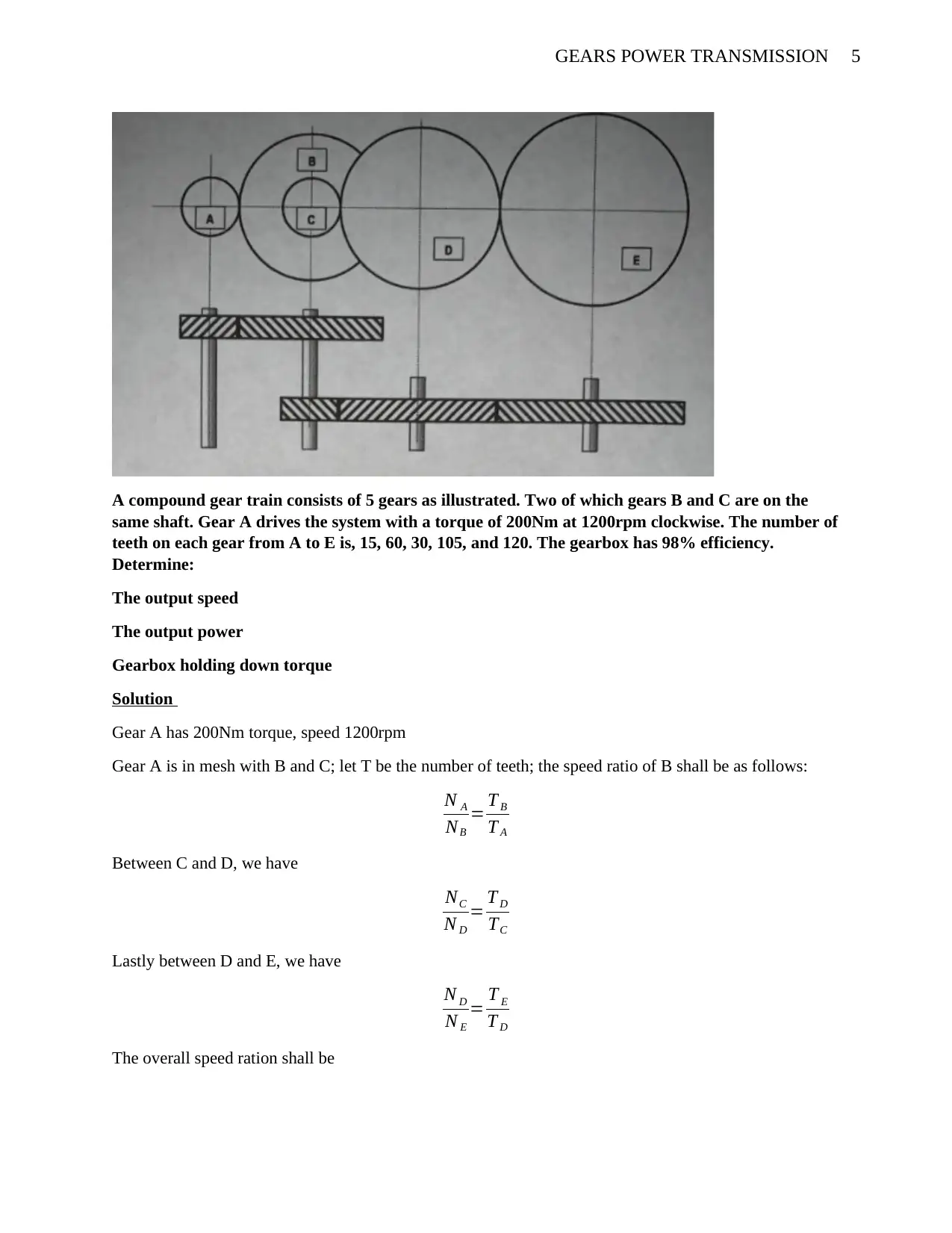
A compound gear train consists of 5 gears as illustrated. Two of which gears B and C are on the
same shaft. Gear A drives the system with a torque of 200Nm at 1200rpm clockwise. The number of
teeth on each gear from A to E is, 15, 60, 30, 105, and 120. The gearbox has 98% efficiency.
Determine:
The output speed
The output power
Gearbox holding down torque
Solution
Gear A has 200Nm torque, speed 1200rpm
Gear A is in mesh with B and C; let T be the number of teeth; the speed ratio of B shall be as follows:
N A
NB
= T B
T A
Between C and D, we have
NC
N D
= T D
TC
Lastly between D and E, we have
N D
N E
= T E
T D
The overall speed ration shall be
6GEARS POWER TRANSMISSION
N A
NB
X NC
N D
X N D
N E
= T B
T A
X T D
T C
X T E
T D
Since gears B and C are mounted on the same shaft, therefore NB =NC
Therefore, we shall have: N A
N E
= T B
T A
X T D
T C
X T E
T D
NE is the output speed; 1200
NE
=60
15 X 105
30 X 120
105
N E=75 rpm , theoutput speed
The output power shall be calculated as:
Input torque =200Nm, speed = 1200rpm (convert this to r.p.s, which shall be 20rps)
Input power shall be 200 X 20 = 4000W or 4kW
Output power shall be: efficiency X input power = 0.98X4000 = 3920W or 3.92kW
Turns ratio (input and output) multiplied by power, we shall have the gearbox holding down torque: (Barr
& Bansal, 2006)
N A
N E
X output power
1200
75 X 3.92=62.72 Nm
N A
NB
X NC
N D
X N D
N E
= T B
T A
X T D
T C
X T E
T D
Since gears B and C are mounted on the same shaft, therefore NB =NC
Therefore, we shall have: N A
N E
= T B
T A
X T D
T C
X T E
T D
NE is the output speed; 1200
NE
=60
15 X 105
30 X 120
105
N E=75 rpm , theoutput speed
The output power shall be calculated as:
Input torque =200Nm, speed = 1200rpm (convert this to r.p.s, which shall be 20rps)
Input power shall be 200 X 20 = 4000W or 4kW
Output power shall be: efficiency X input power = 0.98X4000 = 3920W or 3.92kW
Turns ratio (input and output) multiplied by power, we shall have the gearbox holding down torque: (Barr
& Bansal, 2006)
N A
N E
X output power
1200
75 X 3.92=62.72 Nm
⊘ This is a preview!⊘
Do you want full access?
Subscribe today to unlock all pages.

Trusted by 1+ million students worldwide
7GEARS POWER TRANSMISSION
Task 3
An epicyclic speed reduction gearbox is 98% efficient with rated maximum power input of 2.5MW
at its nominal input on the sun gear of 7500rpm. Gearbox output is from the planet carrier with the
annulus ring fixed. The planet gears have 60 teeth and the sun gear 40 teeth. Determine:
a. The number of annulus teeth
b. Produce a table of gear ratio for sun, planet, annulus, and planet carrier
c. The output gear ratio
d. The nominal output speed and its direction or rotation
e. The nominal holding torque
f. The nominal output torques
Solution
Input parameters
Sun gear is 7500rpm (125rps), teeth = 40;
Output parameters
Planet gear =60 teeth,
The overall gear equation of the planetary gear system, which represents the sun-planet and the planet-
ring is given by:
Ns ωs + N p ωp − ( Ns + N p ) ωc=0
Nr ωr−N p ω p− ( N r−N p ) ωc=0
Where; ωr , ωs , ω p , ωcis the angular velocities of the Ring, Sun gear, planet and the carrier in that order
Nr , N p , N sis the teeth number ring, each planet, and the sun respectively.
To get the number of teeth, we shall consider the following equation:
Nr =Ns +2 NP
On substituting we get:
Nr =40+120=160 teeth
The three items can be considered to be input, or the output, or they can be sometimes be held stationary.
Each of them at different capacities determine the gear ratio to the set. The results shall be written in the
equations below, but main equation becomes is
( R−1 ) ωc=Rωr −ωs :Where R= N r
N s
The results are (which shall be calculated using the number of teeth)
1+ R
S ; when the Sun is statieonary
Paraphrase This Document
Need a fresh take? Get an instant paraphrase of this document with our AI Paraphraser
8GEARS POWER TRANSMISSION
1
1+ S
R
; when the Carrier is stationary
−R
S : whenthe annulusring is stationary
The table shall be:
Item I/P O/P Fixed Calculation GR
A The sun Carrier Annulus Ring 1 + RS/SS 5:1
B Carrier Annulus Ring The Sun 1 / (1 + SS/RS) 0.8:1
C Carrier Annulus Ring Carrier -RS/SS -5:1
The output gear ratio we shall say the annulus is fixed, then the gear ratio becomes 5:1
Output speed
We shall consider that the epicyclic gear we are having is to reduce speed,
Therefore, the output speed is obtained by;
(1500 X 2 π)/60 = 157.08rpm
Nominal input torque pI/ωI but ωI = (7500 X 2π)/60 = 784.4rps, therefore Nominal input torque
= 2500/784.4 = 3.187Nm
Output torque = (Eff. X tI X ωI)/ωo = (0.98 X 3.18 X 784.4)/157.08 = 15.56Nm
Nominal holding toque = T1 – T2 = 3.18 – 15.56 = -12.38Nm
References
9GEARS POWER TRANSMISSION
Barr, J. S., & Bansal, R. K. (2006). A text Book Theory of Machines; Gears. Delhi: Laxmi Publications.
The Engineering Mindset. (2018, June 1). Pulley Belt CALCULATIONS - Belt length, distance between
pulley wheels. Retrieved from Engineering mindset: https://www.youtube.com/watch?
v=yxCBhD9nguw&lc=UgiXIXFNrRCsy3gCoAEC
⊘ This is a preview!⊘
Do you want full access?
Subscribe today to unlock all pages.

Trusted by 1+ million students worldwide
1 out of 9
Your All-in-One AI-Powered Toolkit for Academic Success.
+13062052269
info@desklib.com
Available 24*7 on WhatsApp / Email
![[object Object]](/_next/static/media/star-bottom.7253800d.svg)
Unlock your academic potential
Copyright © 2020–2025 A2Z Services. All Rights Reserved. Developed and managed by ZUCOL.
