ENGR-3016 Summer 2018: Mechanical Power Transmission Project
VerifiedAdded on 2022/09/14
|7
|1404
|27
Project
AI Summary
This project focuses on the design of a mechanical power transmission system utilizing a helical bevel geared motor to enhance speed in a factory setting. The project begins with an introduction to the importance of mechanical systems in increasing production efficiency and the role of engineers in addressing speed-related challenges. It delves into the specifics of bevel gears, their configurations, and their application in increasing motor speed. The client problem involves increasing the pumping speed of a motor, which is addressed by designing a gear system to modify the output speed. The project includes detailed calculations for gear ratios, pitch angles, and speed determination to achieve the desired output speed. The solution also includes drawings to illustrate the system's components and their arrangement. The conclusion emphasizes the suitability of the chosen gear system for the client's needs, considering space and operational requirements. References to relevant sources are also provided.

1POWER TRANSMISSION PROJECT
Mechanical Design: Power Transmission Project
[Name]
[Course]
[Prof/Tutor….]
[Date]
Mechanical Design: Power Transmission Project
[Name]
[Course]
[Prof/Tutor….]
[Date]
Paraphrase This Document
Need a fresh take? Get an instant paraphrase of this document with our AI Paraphraser
2POWER TRANSMISSION PROJECT
Introduction
Today in the world humans have the urge to make things faster, develop systems faster and
processes. Engineers are the ones that are usually confronted with these kinds of challenges
or ideas for production to be made faster. Machines are made exactly for that, where they
have the mechanical systems to enhance speed. Some machines can be used in the right
production places but the speed might be too much, so engineers will develop systems to
make sure the speed of these systems are reduced. The right assembly of mechanisms and
machine components are needed so long as they are well specified for the manufacture to
develop them as per the requirements.
Gear drives are complicated mechanical systems that are in most of the machinery types,
especially the ones that deals with locomotion, like automobiles, robots, aircrafts, trains, even
robots. The design of gear system needs to be carried out carefully that is why it seems
tedious and consuming a lot of time. Though this depends on the technicality of the system
and where the system shall be applied. In the design of the gear system, the configuration of
it really matters and is what must be done keenly in design. Configurations starts from the
gear shafts, the gears themselves, bearings, clutches, and couplings which are connected
together to form a gear transmission system in the power flow of a machine. When decision
is made early in the design, influences the successes of the final product which also proves to
be cost effective at the end.
This paper is concerned with a design of a mechanical power transmission system of a helical
bevel geared motor. The system shall be dissected and the components that makes up the
system specified. The system shall be mounted on a motor to enhance its speed this is
suitable in increasing the rate of production in a factory. the best place to start is in the
understanding of the bevel gears, then how they are mounted on the motor and other
components. Before talking about that, the motor that needs reinforcement shall be an
induction motor, either single or three-phase. Our focus in this motor, shall be the
synchronous speed, which is the speed at which the magnetic field rotates (Electrical 4U,
2019). This is usually dependent on the number of poles and the frequency; both are
determined by the manufacturer.
Bevel Gears
Bevel gears are gears where a pair of axes of the two shafts intersect, and the faces that bears
the tooth are shaped conically. In the context of bevel gearing system, the pitch surface and
pitch angle are important. The pitch surface of a gear system is an imaginary surface that is
toothless that aids in the making an average of the peaks and valleys of the individual teeth.
Bevel gears are commonly used in mining industry, aerospace, textile and many other fields
(Deep, 2019). the use of these gears is wide, and for this context they shall be employed for
increasing motor speed. The bevel gears are advantageous in the following ways: they do not
take a lot of space, large amount of energy is transmitted through them, they perform highly
compared to other gears, their maintenance requirement is very basic, and they reduce the
chances of slip.
The Client Problem
The client would like to have a pump from this motor, and because a lot of water is required,
the pumping speed must be increased, which is dependent on the speed of motor. According
3POWER TRANSMISSION PROJECT
to the client, the motor speed doesn’t achieve the intended demand of delivering water to his
clients at the right time. So, one of the suggestions is to have a gear system attached to the
motor to ensure the speed is increased. We know that the motor rated speed in RPM cannot
be changed since this speed is governed by the number of poles and the slip. Therefore, our
work is to identify the suitable gear system that will change the output speed or the shaft
speed and reduce the effective torque.
Calculations
As it’s always known, a gear is made up of teeth or toothed wheels which is attached to the
shafts. One of the many properties of gear system is the speed ratio, which is also referred to
as fear ratio. This is the ratio of the speed that the gears turn with at the point of input to the
output of the gear, in other words, the motor original speed (or rated speed) is the input and
the output of what the gear will generate. The simplest calculation or where to start from, is
how the output speed relates with input speed and the speed ratio.
Output Speed = Input speed/ speed ratio
In the gear system we are dealing with, obviously has two gears, where the number of teeth
(T) in one gear is different from the other gear. To compare the two, we shall have an
equation that relates the speed (N) to the number of teeth, given by:
T A
T B
= N B
N A
… … … … … … … … .(1)
For the bevel gear calculations, the bevel tooth elements are tapered the dimensions of the
tooth and pitch diameter have to be taken into consideration. Here we shall determine
parameters like the velocity ratio, i, which is derived from the ratio of different parameters.
i= z1
z2
= d1
d2
= sin δ1
sin δ2
… … … … … … …(2)
Where, δ is the pitch angle, and z1∧z2are the pinion and the gear tooth number respectively,
consider the following equation
tan δ1= sin θ
( z2
z1 )+cos θ
tan δ2= sin θ
( z1
z2 )+cos θ
… … … … … … ..(3)
⊘ This is a preview!⊘
Do you want full access?
Subscribe today to unlock all pages.

Trusted by 1+ million students worldwide
4POWER TRANSMISSION PROJECT
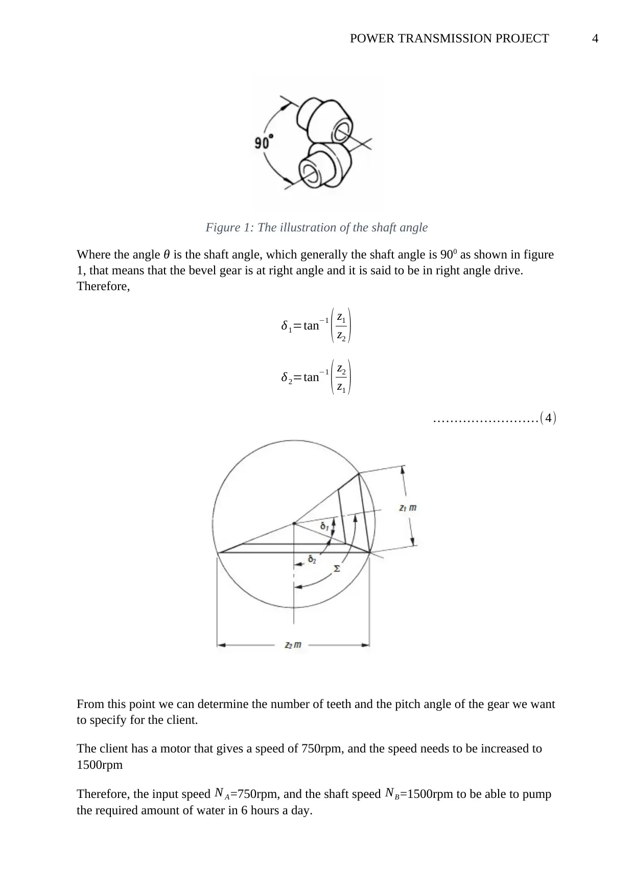
Figure 1: The illustration of the shaft angle
Where the angle θ is the shaft angle, which generally the shaft angle is 900 as shown in figure
1, that means that the bevel gear is at right angle and it is said to be in right angle drive.
Therefore,
δ1=tan−1
( z1
z2 )
δ2=tan−1
( z2
z1 )
… … … … … … … … .( 4)
From this point we can determine the number of teeth and the pitch angle of the gear we want
to specify for the client.
The client has a motor that gives a speed of 750rpm, and the speed needs to be increased to
1500rpm
Therefore, the input speed N A=750rpm, and the shaft speed NB=1500rpm to be able to pump
the required amount of water in 6 hours a day.
Paraphrase This Document
Need a fresh take? Get an instant paraphrase of this document with our AI Paraphraser
5POWER TRANSMISSION PROJECT
The pitch angle, shall be deemed to be around 25.650 and 154.40 for δ 1 and δ2 respectively,
tan δ1=tan 25.650=0.48 1
¿ 12
25
tan δ1=tan 154.40=−0.4 8
The negative value denotes the opposite, which now when converted, becomes the same as:
¿ 12
25
The Drawings
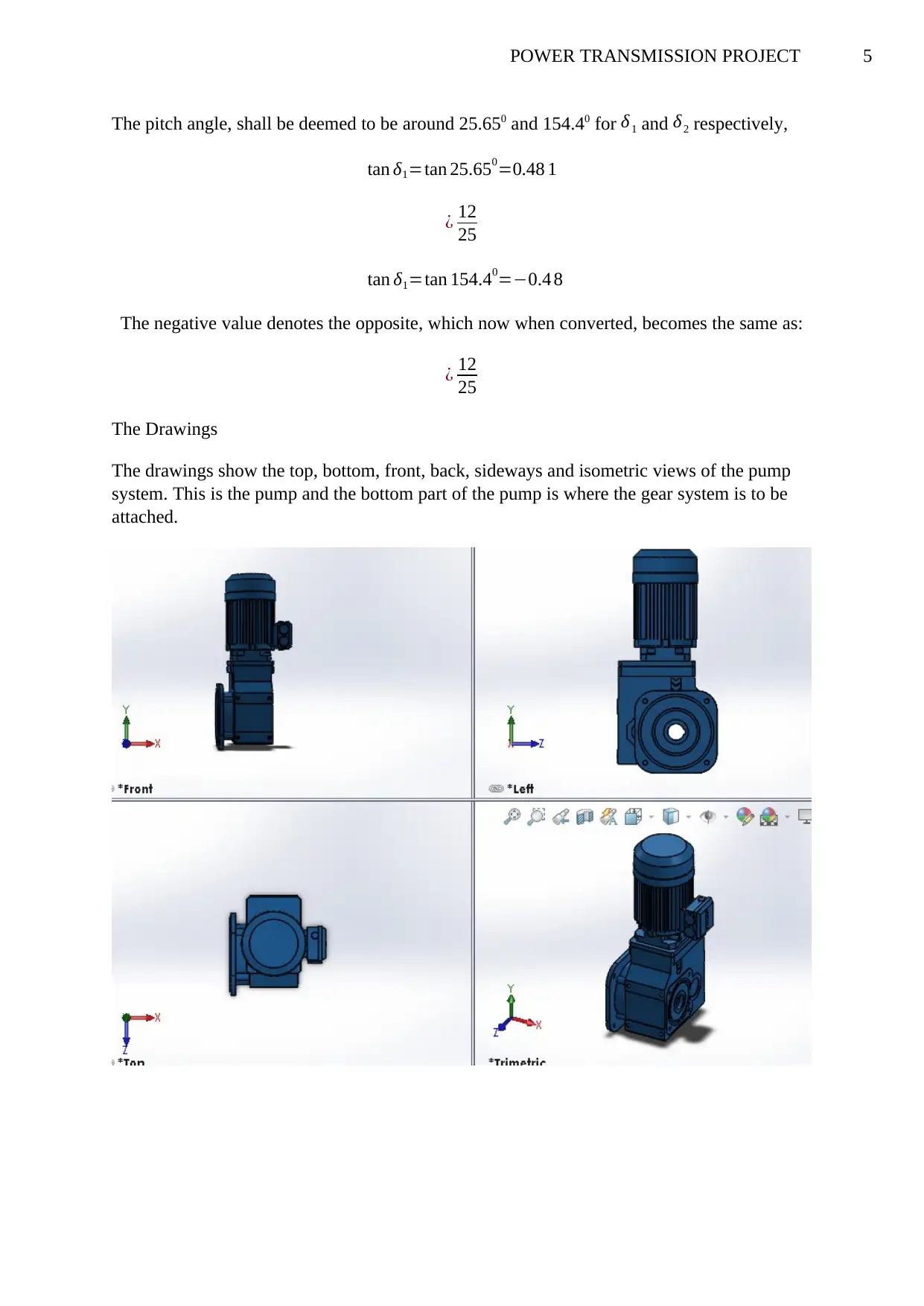
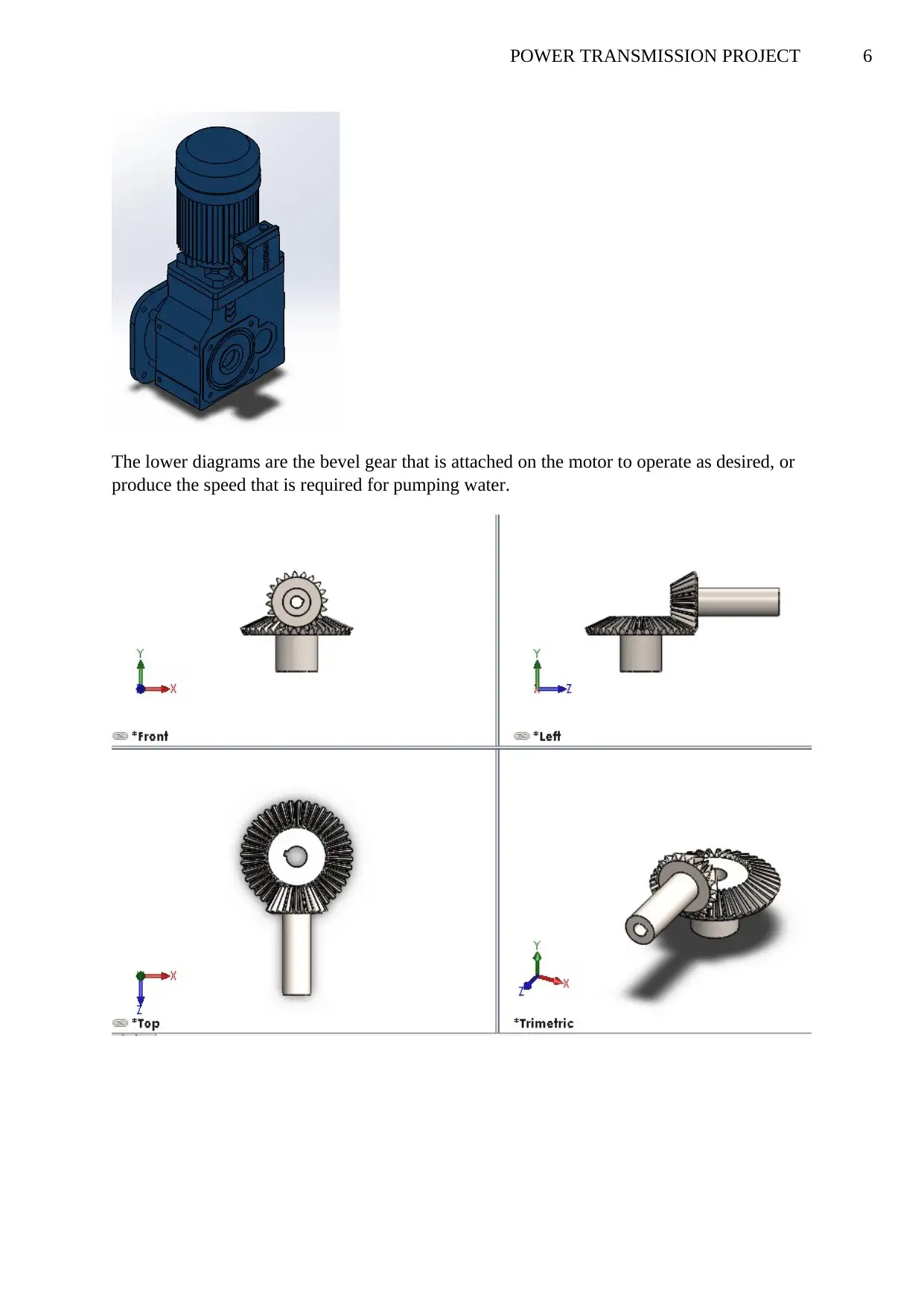
The drawings show the top, bottom, front, back, sideways and isometric views of the pump
system. This is the pump and the bottom part of the pump is where the gear system is to be
attached.
6POWER TRANSMISSION PROJECT
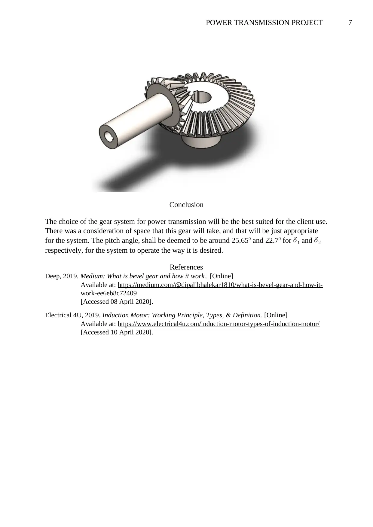
The lower diagrams are the bevel gear that is attached on the motor to operate as desired, or
produce the speed that is required for pumping water.
The lower diagrams are the bevel gear that is attached on the motor to operate as desired, or
produce the speed that is required for pumping water.
⊘ This is a preview!⊘
Do you want full access?
Subscribe today to unlock all pages.

Trusted by 1+ million students worldwide
7POWER TRANSMISSION PROJECT
Conclusion
The choice of the gear system for power transmission will be the best suited for the client use.
There was a consideration of space that this gear will take, and that will be just appropriate
for the system. The pitch angle, shall be deemed to be around 25.650 and 22.70 for δ1 and δ2
respectively, for the system to operate the way it is desired.
References
Deep, 2019. Medium: What is bevel gear and how it work.. [Online]
Available at: https://medium.com/@dipalibhalekar1810/what-is-bevel-gear-and-how-it-
work-ee6eb8c72409
[Accessed 08 April 2020].
Electrical 4U, 2019. Induction Motor: Working Principle, Types, & Definition. [Online]
Available at: https://www.electrical4u.com/induction-motor-types-of-induction-motor/
[Accessed 10 April 2020].
1 out of 7
Related Documents
Your All-in-One AI-Powered Toolkit for Academic Success.
+13062052269
info@desklib.com
Available 24*7 on WhatsApp / Email
![[object Object]](/_next/static/media/star-bottom.7253800d.svg)
Unlock your academic potential
Copyright © 2020–2026 A2Z Services. All Rights Reserved. Developed and managed by ZUCOL.


