Bending Moments, Shear Forces, and Beam Design Considerations
VerifiedAdded on 2022/11/14
|21
|2791
|55
Homework Assignment
AI Summary
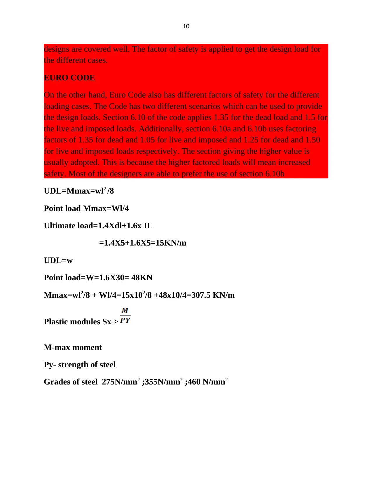
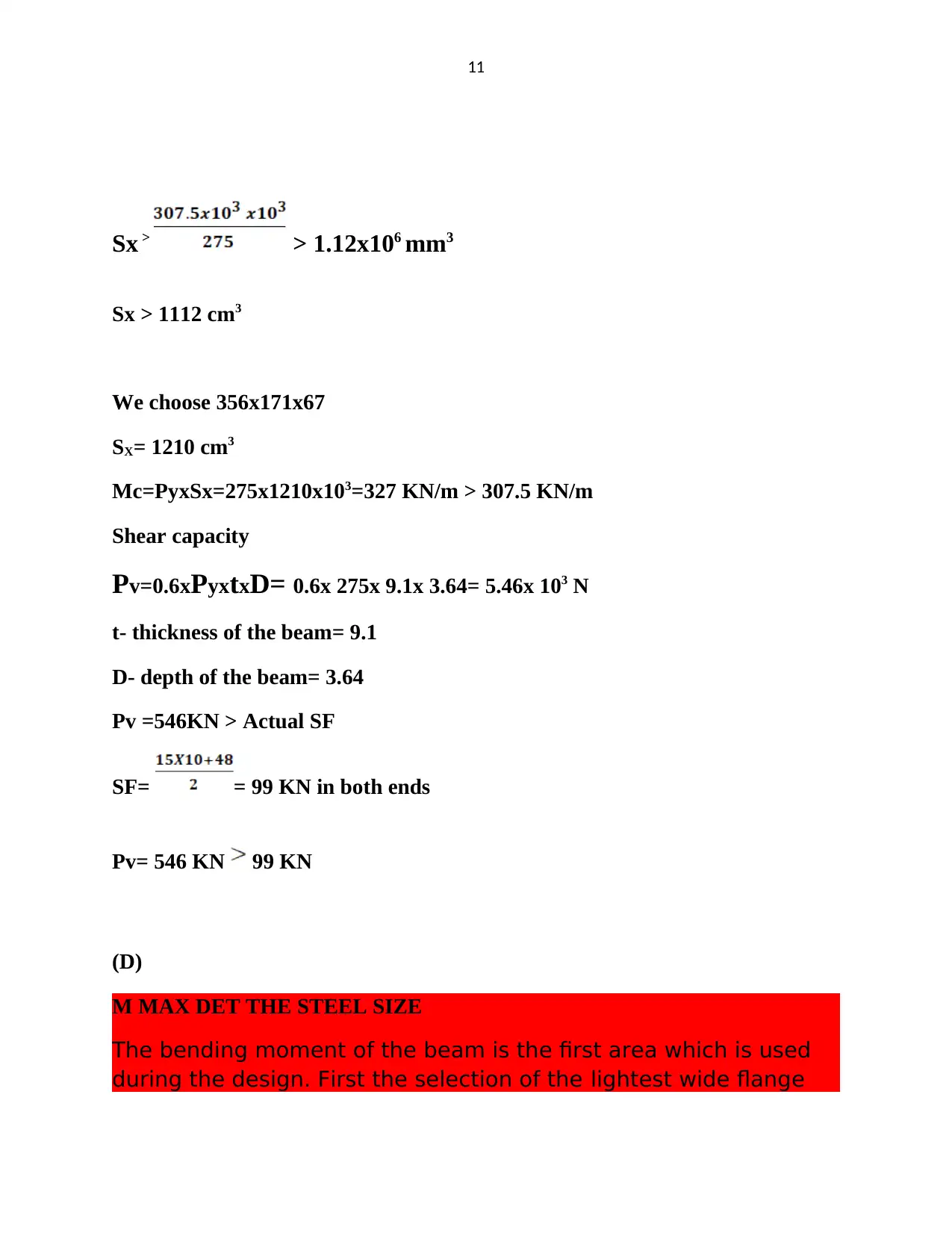
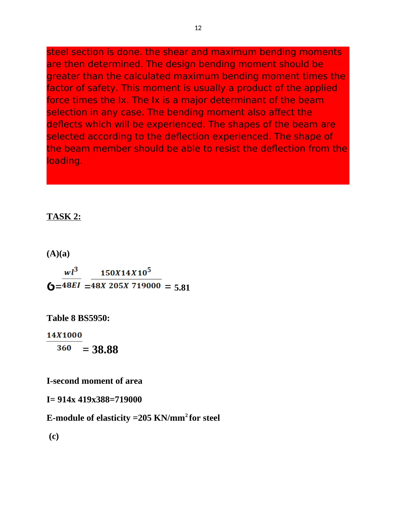
This assignment solution addresses the principles of structural design, encompassing calculations for bending moments and shear forces in simply supported steel and concrete beams. It delves into the determination of deflection, calculation of axial load carrying capacity of steel and reinforced concrete columns, and explores design methods for beams and columns. The solution includes an analysis of statutory requirements for structural designs, safety factors for various loads, and the impact of bending moments on steel beam selection. Furthermore, it evaluates different support methods, deflection in beams, and materials for construction, including the use of Building Information Modeling (BIM) for design and construction. The document provides detailed calculations, explanations, and design considerations for various structural elements.

1
Principles of Structural
Design
Table of Contents
Principles of Structural
Design
Table of Contents
Paraphrase This Document
Need a fresh take? Get an instant paraphrase of this document with our AI Paraphraser

2
Task 1:.............................................................................................................................................2
Task 2:...........................................................................................................................................12
Task 3:...........................................................................................................................................15
Bibliography..................................................................................................................................17
Task 1:
(A)
(a)SF at A=75 KN
Change on SF from a to c1=0

3
SFa to c1=75KN
SFa to c2=150-75= -75KN
Change to SF from c2 to B=0
SFB= -75 KN
Bending moment
Max=Area of diagram= =525 KN
(b)ℇRA=0
RBX8-65X2=0
RB=16.25KN
SFa to c1=75KN
SFa to c2=150-75= -75KN
Change to SF from c2 to B=0
SFB= -75 KN
Bending moment
Max=Area of diagram= =525 KN
(b)ℇRA=0
RBX8-65X2=0
RB=16.25KN
⊘ This is a preview!⊘
Do you want full access?
Subscribe today to unlock all pages.

Trusted by 1+ million students worldwide

4
RA=48.75KN
SF at A=48.75KN
SF at c1=48.75KN
SF at c2=48.75-65= -16.25KN
Change from c2 to B=0
SF at B= -16.25KN
Bending moment Max=Area of diagram= = 130KN
(c)
RA+RB=SXF
RA=48.75KN
SF at A=48.75KN
SF at c1=48.75KN
SF at c2=48.75-65= -16.25KN
Change from c2 to B=0
SF at B= -16.25KN
Bending moment Max=Area of diagram= = 130KN
(c)
RA+RB=SXF
Paraphrase This Document
Need a fresh take? Get an instant paraphrase of this document with our AI Paraphraser

5
RA+RB=625KN
RA= 312.5KN
RB=312.25 KN
SF at A=312.25KN
SF at B= -312.25 KN
BM=Area of diagram= = 1953.125 KN/m
(d)
RA+RB=625KN
RA= 312.5KN
RB=312.25 KN
SF at A=312.25KN
SF at B= -312.25 KN
BM=Area of diagram= = 1953.125 KN/m
(d)

6
RA+RB= = 215KN
SF at A=215KN
RA= 215 KN
RB=215KN
Change in SF from A to c= 215-140=75KN
SFc2= -75KN
Change in SF from c2 to B= -15-140= -215 KN
BM=Area of diagram=75x7+ = 1015KN
RA+RB= = 215KN
SF at A=215KN
RA= 215 KN
RB=215KN
Change in SF from A to c= 215-140=75KN
SFc2= -75KN
Change in SF from c2 to B= -15-140= -215 KN
BM=Area of diagram=75x7+ = 1015KN
⊘ This is a preview!⊘
Do you want full access?
Subscribe today to unlock all pages.

Trusted by 1+ million students worldwide

7
(e)
RA+RB= 625+50=675 KN
RA1=312 KN
RB1=312 KN
RBX20-15X50=7
(e)
RA+RB= 625+50=675 KN
RA1=312 KN
RB1=312 KN
RBX20-15X50=7
Paraphrase This Document
Need a fresh take? Get an instant paraphrase of this document with our AI Paraphraser

8
RA= 20KN
RB= 30 KN
RA+RB= 625+50=675 KN
RA1=312.5 KN
RB1=312.5 KN
RBX25-15X50=15
RA= 20KN
RB= 30 KN
RA=332.5 KN
RB=342.5 KN
SF from A to c1
332.5-25x15= -42.5 KN
SF from c1 to c2
-42.5-50= -92.5 KN
SF from c2 to B
-92.5-25X10= -342.5 KN
BMc1 == 2211.125
15-13.3= 1.7 m
= 36.12
RA= 20KN
RB= 30 KN
RA+RB= 625+50=675 KN
RA1=312.5 KN
RB1=312.5 KN
RBX25-15X50=15
RA= 20KN
RB= 30 KN
RA=332.5 KN
RB=342.5 KN
SF from A to c1
332.5-25x15= -42.5 KN
SF from c1 to c2
-42.5-50= -92.5 KN
SF from c2 to B
-92.5-25X10= -342.5 KN
BMc1 == 2211.125
15-13.3= 1.7 m
= 36.12

9
BMc2= 2211.125-36.12=2175
(B)
CDM2007 SAFETY REGULATION
Statutory requirements to ensure safety in structural designs
Safety in structural design is a key consideration to ensure when designing. All the
codes and regulations are designed to ensure safety regulations take a key point.
The major statutory requirement to ensure safety in designs are anchored on the
maintaining of the stability of the structure against either turning, sliding of
buckling. BS, Euro Code and code of conduct offers the key procedures of
ensuring safety measures are attained during design1. The statutory requirement
also requires the design to be able to meet the minimum strength to resist the safely
imposed stresses which are created by the loads. Lastly, the regulations also
require that the serviceability of the designed members is met. This ensures that
satisfactory performance is well achieved. The design of the stiffness and enough
reinforcement to contain the deflects and cracking is covered under this section.
(C)
BRITISH CODE
Explore, explain and produce valid factors of safety for live loads, dead loads and
imposed loads
Factors of safety are meant to ensure that the designs are able to meet the safety
factors. The British code is able to apply a factor of safety of 1.4 for the dead load
and 1.6 for both imposed and live loads. These factors ensure that the safety of the
1 Buchanan, Andrew Hamilton, and Anthony k Abu. Structural design for fire safety. (Chichester: John Wiley 2017).
⊘ This is a preview!⊘
Do you want full access?
Subscribe today to unlock all pages.

Trusted by 1+ million students worldwide

10
designs are covered well. The factor of safety is applied to get the design load for
the different cases.
EURO CODE
On the other hand, Euro Code also has different factors of safety for the different
loading cases. The Code has two different scenarios which can be used to provide
the design loads. Section 6.10 of the code applies 1.35 for the dead load and 1.5 for
the live and imposed loads. Additionally, section 6.10a and 6.10b uses factoring
factors of 1.35 for dead and 1.05 for live and imposed and 1.25 for dead and 1.50
for live and imposed loads respectively. The section giving the higher value is
usually adopted. This is because the higher factored loads will mean increased
safety. Most of the designers are able to prefer the use of section 6.10b
UDL=Mmax=wl2 /8
Point load Mmax=Wl/4
Ultimate load=1.4Xdl+1.6x IL
=1.4X5+1.6X5=15KN/m
UDL=w
Point load=W=1.6X30= 48KN
Mmax=wl2/8 + Wl/4=15x102/8 +48x10/4=307.5 KN/m
Plastic modules Sx >
M-max moment
Py- strength of steel
Grades of steel 275N/mm2 ;355N/mm2 ;460 N/mm2
Paraphrase This Document
Need a fresh take? Get an instant paraphrase of this document with our AI Paraphraser

11
Sx > > 1.12x106 mm3
Sx > 1112 cm3
We choose 356x171x67
SX= 1210 cm3
Mc=PyxSx=275x1210x103=327 KN/m > 307.5 KN/m
Shear capacity
Pv=0.6xPyxtxD= 0.6x 275x 9.1x 3.64= 5.46x 10³ N
t- thickness of the beam= 9.1
D- depth of the beam= 3.64
Pv =546KN > Actual SF
SF= = 99 KN in both ends
Pv= 546 KN 99 KN
(D)
M MAX DET THE STEEL SIZE
The bending moment of the beam is the first area which is used
during the design. First the selection of the lightest wide flange

12
steel section is done. the shear and maximum bending moments
are then determined. The design bending moment should be
greater than the calculated maximum bending moment times the
factor of safety. This moment is usually a product of the applied
force times the Ix. The Ix is a major determinant of the beam
selection in any case. The bending moment also affect the
deflects which will be experienced. The shapes of the beam are
selected according to the deflection experienced. The shape of
the beam member should be able to resist the deflection from the
loading.
TASK 2:
(A)(a)
=Ỽ = = 5.81
Table 8 BS5950:
= 38.88
I-second moment of area
I= 914x 419x388=719000
E-module of elasticity =205 KN/mm2 for steel
(c)
⊘ This is a preview!⊘
Do you want full access?
Subscribe today to unlock all pages.

Trusted by 1+ million students worldwide
1 out of 21
Your All-in-One AI-Powered Toolkit for Academic Success.
+13062052269
info@desklib.com
Available 24*7 on WhatsApp / Email
Unlock your academic potential
Copyright © 2020–2025 A2Z Services. All Rights Reserved. Developed and managed by ZUCOL.