Finite Element Analysis of Cantilever and Oil Platform Structures
VerifiedAdded on 2022/12/27
|5
|2001
|1
Project
AI Summary
This project presents a finite element analysis (FEA) of two structural engineering problems: a cantilever beam and an oil platform. The cantilever beam analysis explores the idealization of the structure using 1D beam, 2D plate, and 3D solid finite elements, comparing their deflection results against analytical solutions and conducting a mesh convergence study. A parametric analysis investigates the impact of length-to-width and length-to-thickness ratios on the beam's deflection. The second part of the project focuses on an oil platform modeled as a space frame, determining its translational and rotational displacements under applied loads. Recommendations are provided for design improvements, including increasing cross-sectional dimensions, adding diagonal members, and using materials with higher Young's modulus. The project utilizes Abaqus CAE 6.13 Standard for simulations, and the findings highlight the accuracy of different element types and the importance of structural parameters. The solutions also provides insights on how to improve the design of the structures.
Problem A Solution:
Introduction:
Given the problem is regarding the cantilever structure made of steel material with E =
200GPa and ʋ = 0.3. The objective of the problem is to idealise the cantilever structure with
beam, plate and 3D-solid finite elements and study the behaviour of the cantilever structure.
Parametric analysis for different length to width ratio, length to thickness ratio and mesh
elements for beam or plate elements is also required to understand the design of the cantilever
structure.
Analysis:
1. The initial length, width and thickness of the cantilever structure chosen are 100 mm, 30
mm and 4 mm.
2. The initial mesh size chosen for performing the FE analysis is 100X30X4. The parameter
used to compare results for various conditions is the deflection of the beam in the load
direction, and hence the loading is applied using force control. The force P is equal to
1000N.
3. 1D wire FE linear elements are used to model the beam structure with a rectangular
profile of assumed dimensions. 2D Planar shell linear elements are used to idealise the
cantilever structure with plate elements. 3D Hexahedral linear brick elements are used to
idealise the cantilever structure with solid elements [1].
4. Abaqus CAE 6.13 Standard is used to solve the problem [2].
Findings:
1. The deflection of the cantilever structure is used as a parameter to understand the
cantilever structure idealisation for beam, plate and solid elements. Deflection of the
structure is also used as a parameter to study the beam structure with various boundary
conditions.
2. The analytical solution using Euler-Bernoulli beam theory [2] for a given dimension is
10.41667 mm (δ= P L3
3 EI ).
3. The numerical results are compared with the analytical solution to quantify the error in
the results.
Results:
1. The following Table 1 shows the mesh convergence study on the various FE models with
various conditions. The deflection of the FE model is observed to find the right
combination of the FE elements.
2. The increase in the FE elements of the model can produce a stable output result and
produce a result with mesh independence. From Table 1, it is clear that the finite elements
required for beam idealisation are 100 and for plate and 3D solid elements are 100 x 30.
3. The number of finite elements present along the thickness direction for 3D solid elements
idealisation is essential to get the desired output result. The required deflection is close to
the analytical solution when the thickness of the 3D FE model is idealised with six finite
elements.
Paraphrase This Document
Need a fresh take? Get an instant paraphrase of this document with our AI Paraphraser
4. The 3D-solid elements resemble the actual behaviour of the structure and can accurately
produce the desired results due to loading when compared to the beam and plate elements
idealisation. The deflection of the cantilever structure with 3D solid elements is equal to
10.46191, and the value exceeds the analytical solution.
Table 1. Mesh convergence study for various conditions in the given problem
Boundary Conditions 20 Finite Elements 50 Finite elements 100 Finite elements
Cantilever Beam 10.427880 10.429167 10.429351
Fixed-Fixed Support 0.161692 0.165882 0.165931
Simply Supported 0.653845 0.654167 0.654213
Cantilever Idealisation
(L X b) 50 X 15 100 X 30 200 X 60
Plate 10.208829 10.210881 10.212087
3D Solid (L X b)
Elements 10.206558 10.461905 10.653809
3D Solid Thickness
Elements for (100 X 30 ) 10.843363 (4 FE’s) 10.461905 (6 FE’s) 10.276772 (10 FE’s)
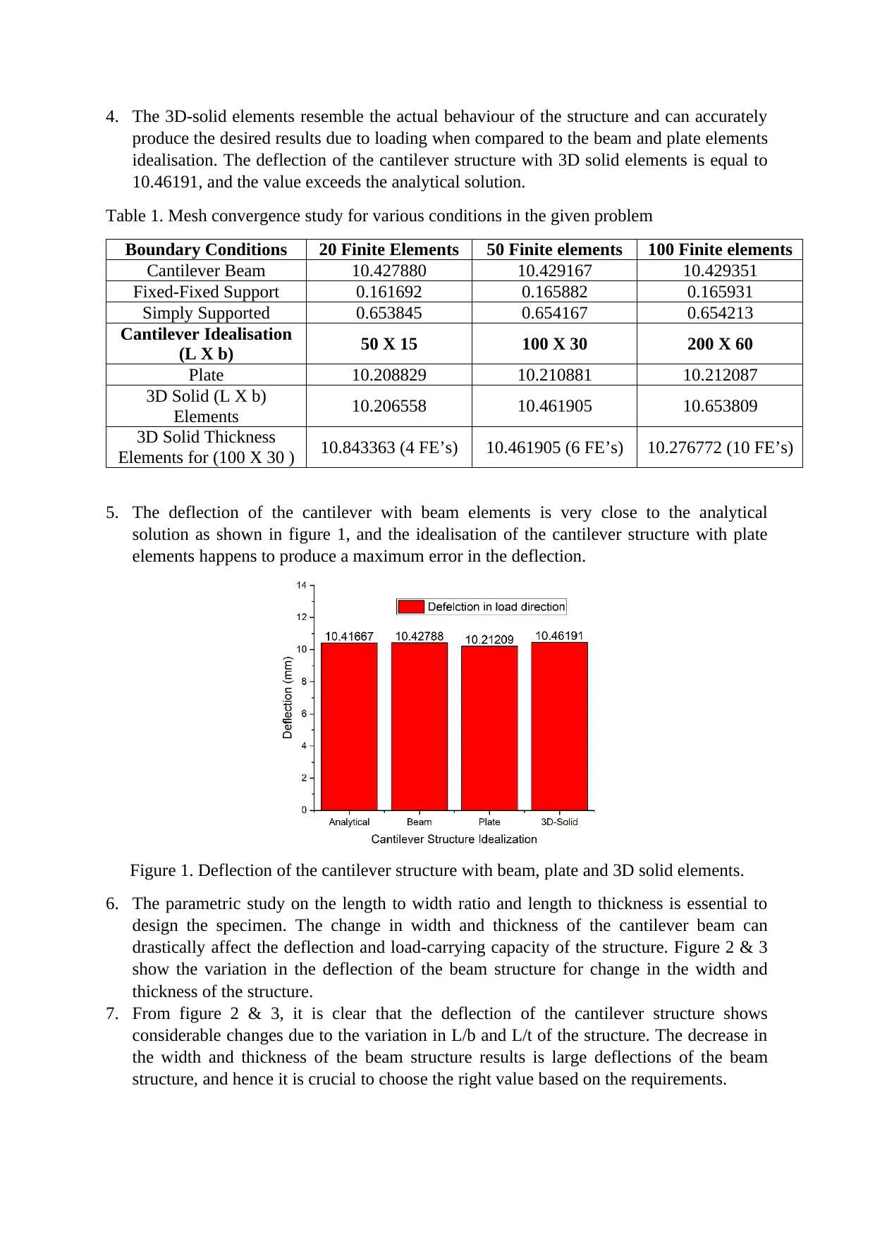
5. The deflection of the cantilever with beam elements is very close to the analytical
solution as shown in figure 1, and the idealisation of the cantilever structure with plate
elements happens to produce a maximum error in the deflection.
Figure 1. Deflection of the cantilever structure with beam, plate and 3D solid elements.
6. The parametric study on the length to width ratio and length to thickness is essential to
design the specimen. The change in width and thickness of the cantilever beam can
drastically affect the deflection and load-carrying capacity of the structure. Figure 2 & 3
show the variation in the deflection of the beam structure for change in the width and
thickness of the structure.
7. From figure 2 & 3, it is clear that the deflection of the cantilever structure shows
considerable changes due to the variation in L/b and L/t of the structure. The decrease in
the width and thickness of the beam structure results is large deflections of the beam
structure, and hence it is crucial to choose the right value based on the requirements.
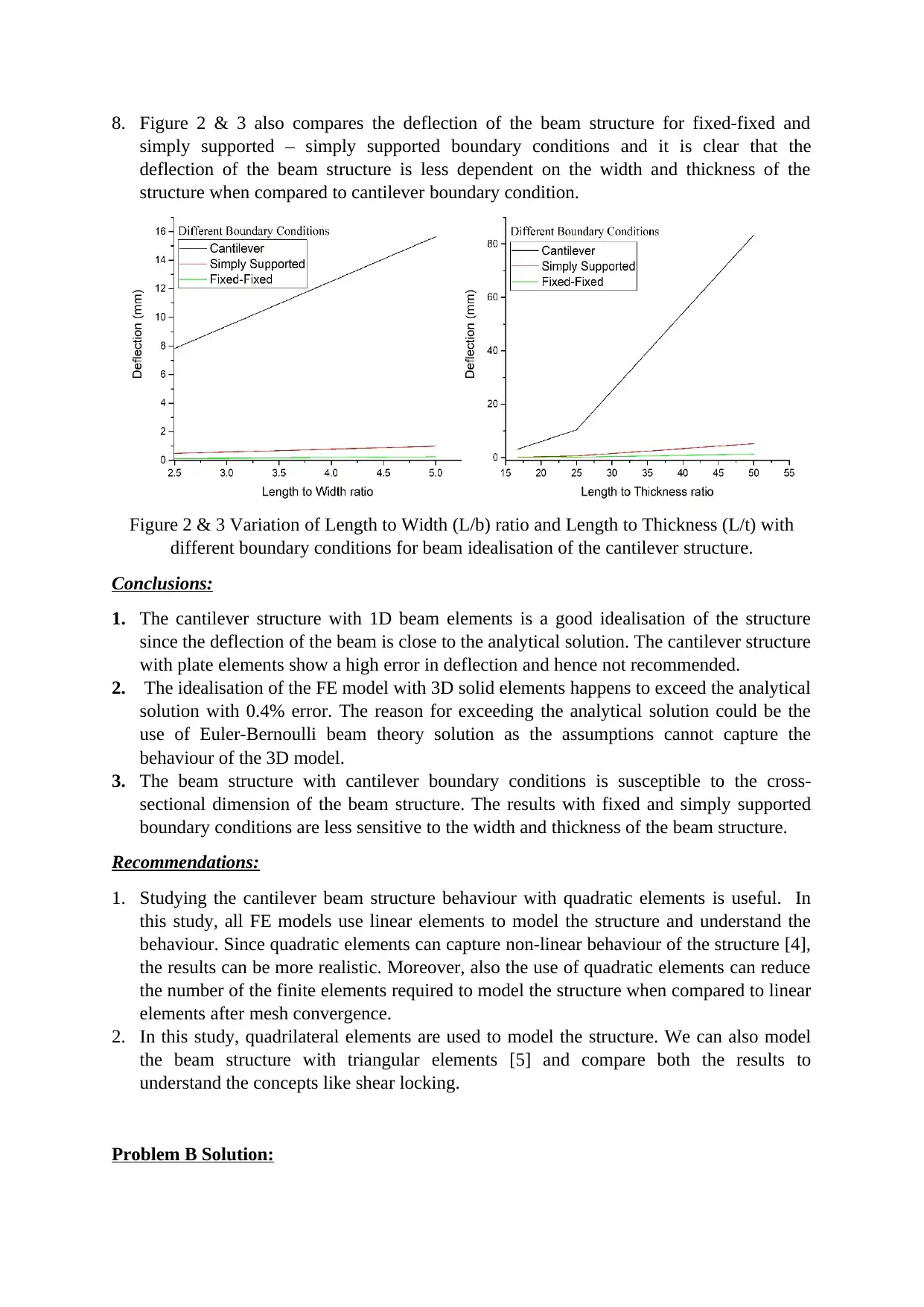
8. Figure 2 & 3 also compares the deflection of the beam structure for fixed-fixed and
simply supported – simply supported boundary conditions and it is clear that the
deflection of the beam structure is less dependent on the width and thickness of the
structure when compared to cantilever boundary condition.
Figure 2 & 3 Variation of Length to Width (L/b) ratio and Length to Thickness (L/t) with
different boundary conditions for beam idealisation of the cantilever structure.
Conclusions:
1. The cantilever structure with 1D beam elements is a good idealisation of the structure
since the deflection of the beam is close to the analytical solution. The cantilever structure
with plate elements show a high error in deflection and hence not recommended.
2. The idealisation of the FE model with 3D solid elements happens to exceed the analytical
solution with 0.4% error. The reason for exceeding the analytical solution could be the
use of Euler-Bernoulli beam theory solution as the assumptions cannot capture the
behaviour of the 3D model.
3. The beam structure with cantilever boundary conditions is susceptible to the cross-
sectional dimension of the beam structure. The results with fixed and simply supported
boundary conditions are less sensitive to the width and thickness of the beam structure.
Recommendations:
1. Studying the cantilever beam structure behaviour with quadratic elements is useful. In
this study, all FE models use linear elements to model the structure and understand the
behaviour. Since quadratic elements can capture non-linear behaviour of the structure [4],
the results can be more realistic. Moreover, also the use of quadratic elements can reduce
the number of the finite elements required to model the structure when compared to linear
elements after mesh convergence.
2. In this study, quadrilateral elements are used to model the structure. We can also model
the beam structure with triangular elements [5] and compare both the results to
understand the concepts like shear locking.
Problem B Solution:
⊘ This is a preview!⊘
Do you want full access?
Subscribe today to unlock all pages.

Trusted by 1+ million students worldwide
Introduction:
Oil platform idealised as a space frame is analysed in this problem with equal force of 4 MN
at 1,2,3,4 nodes. The objective of the problem is to find translational and rotational
displacements of the oil platform space frame for the given load.
Analysis:
1. The linear beam elements with thin-walled pipe cross-section profile are used to the
model of the oil platform space frame with given dimensions. The mesh size value used
in this analysis is one with quadratic beam elements.
2. The space frame is constrained from all possible displacements using fixed boundary
conditions at the bottom nodes 9 – 12 and is subjected to an equal force of 4 MN at nodes
1 – 4.
Finding:
1. To determine the translational and rotational displacements of the space frame in all
possible directions. U1, U2, and U3 are translational displacements about X, Y, Z axis
respectively and UR1, UR2 and UR3 are rotational displacements about Y-Z plane, X-Z
plane and X-Y plane respectively of the space frame.
Results:
Nod
e 1 2 3 4 5 6 7 8 9 10 11 12
U1 0.086 - 0.096 - 0.094 0.089 - 0.0002 0.0002 0 0.0002 0 0 0 0
U2 2.600 2.593 2.71 2.716 - 3.968 - 3.968 - 3.981 - 3.981 0 0 0 0
U3 6.259 6.252 6.78 6.783 3.647 3.647 2.863 2.863 0 0 0 0
UR1 0.054 0.054 0.003 0.010 0.018 0.018 0.037 0.037 0 0 0 0
UR2 - 0.005 0.005 0.006 -0.005 - 0.007 0.007 0.008 - 0.008 0 0 0 0
UR3 0.005 - 0.006 - 0.003 0.003 0 0 -0.001 0.001 0 0 0 0
Table 2 Translational and rotational displacements of the space frame structure
1. The displacements are very significant on 1 to 8 nodes of the structures. It is clear that the
displacements are zero in 9-12 nodes of the frame structure due to fixed boundary
conditions.
2. The maximum translational displacement found at nodes 3 & 4 is 6.78 mm along the
loading direction (Z-axis), and maximum rotational displacement is 0.054 degrees found
at nodes 1 and 2.
Recommendations:
1. Increase in the cross-sectional dimensions of the platform can reduce the deflection and
improve the load-carrying capacity. The twice increase in the diameter and thickness of
the platform cross-section resulted in a reduction of maximum translational displacement
value to 1.659 mm. There is an approximate decrease of 75 % in the maximum deflection
and maximum rotation displacements in the space frame.
Paraphrase This Document
Need a fresh take? Get an instant paraphrase of this document with our AI Paraphraser
2. Increase in the diagonal space members in the structure can significantly reduce the
displacements. Earlier the space frame contains only four diagonal members in the
structure. The deflection of the structure happens about the middle plane at the 5-8 nodal
plane of the structure. The increase in diagonal members to six and eight members
considerably reduced the deflection of the structure due to extra stiffness given to
structure. The maximum deflection is reduced to 5.41 mm and 4.23 mm when diagonal
space members are increases to 6 & 8 members respectively. There is a significant
decrease in the rotational displacements of the space frame. Increasing in cross-sectional
values can further reduce the maximum deflection in the structure.
3. The material with high Young’s modulus can also reduce the deflection in the space
frame.
Conclusions:
1. The CAD model of the oil platform space frame is performed using Abaqus CAE to
determine the translational and rotational displacements for the given load P = 4 MN.
2. The maximum translational and rotational displacements are found to be 6.78 mm and
0.0540 respectively.
3. The further FE analysis to improvise the design of the oil platform shows a reduction in
the displacement in all possible directions due to loading.
References:
1. Wang, E., Nelson, T. and Rauch, R., 2004, May. Back to elements-tetrahedra vs.
hexahedra. In Proceedings of the 2004 international ANSYS conference. Pennsylvania:
ANSYS.
2. ABAQUS, I., 2014. Abaqus documentation. Version, 6, pp.5-1.
3. Han, S.M., Benaroya, H. and Wei, T., 1999. Dynamics of transversely vibrating beams
using four engineering theories. Journal of Sound and vibration, 225(5), pp.935-988.
4. Younis, W., 2010. Up and running with Autodesk Inventor Simulation 2011: a step-by-
step guide to engineering design solutions. Elsevier.
5. Research gate, why are the triangular elements more stiff than the quad ones,
<https://www.researchgate.net/post/In_bending_problems_why_are_the_triangular_elem
ents_more_stiff_than_the_quad_ones>
1 out of 5
Related Documents
Your All-in-One AI-Powered Toolkit for Academic Success.
+13062052269
info@desklib.com
Available 24*7 on WhatsApp / Email
![[object Object]](/_next/static/media/star-bottom.7253800d.svg)
Unlock your academic potential
Copyright © 2020–2026 A2Z Services. All Rights Reserved. Developed and managed by ZUCOL.


