Environmental Engineering Project: SBR Simulation for Nutrient Removal
VerifiedAdded on 2022/08/25
|29
|4614
|22
Project
AI Summary
This project simulates the nitrogen and phosphorus removal process in a granular sequencing batch reactor (SBR) using Aquasim software. The research focuses on mathematically modeling the simultaneous heterotrophic and autotrophic growth within the SBR, considering biofilm, mixed, and settler compartments linked through advective and bifurcation links. The model utilizes the ASM2d model and floc models for biological processes, incorporating stoichiometric coefficients and laboratory data for validation. Key aspects include understanding the kinetics of nitrification and denitrification, the role of aerobic granules, and the impact of factors such as temperature, DO levels, and pH on the process. The project aims to provide insights into reactor performance, the fractions of active biomass, and the efficient removal of nutrients from wastewater, addressing the challenges of stringent discharge standards and eutrophication. The model simulates various parameters, including bacteria profiles, nitrite and nitrate concentrations, and the variation of mixed compartment volume with time. The results highlight the importance of understanding the interactions between autotrophs and heterotrophs for optimizing nutrient removal in wastewater treatment systems.
1
Nitrogen and phosphorus removal process in a granular SBR
Student’s Name
Institutional affiliation
Date
Nitrogen and phosphorus removal process in a granular SBR
Student’s Name
Institutional affiliation
Date
Paraphrase This Document
Need a fresh take? Get an instant paraphrase of this document with our AI Paraphraser
2
Abstract
The objective of this research was to investigate the performance of a granule SBR used in
the removal of nitrogen and phosphorus from wastewater. The removal process of these
elements was mathematically modeled taking into account the simultaneous heterotrophic
and autotrophic growth in the SBR. Aquasim software was then used to simulate the system
using three compartments including the biofilm, mixed and settler compartments. These were
linked using advective links with a bifurcation link circulating Qwaste between the mixed
and biofilm compartments. The results obtained indicate that this model is sufficient for the
validation of experimental data.
Keywords
Autotrophic, heterotrophic, aerobic, anaerobic
Introduction
Nitrogen and phosphorous are crucial constituents of organic materials. The cycle of
these materials in the natural surroundings is one of the key material cycles in the biosphere.
According to Zhu et al., (2018), emissions and water pollution from nitrogen and
phosphorous-based compounds has increased with the rapid growth of manufacturing and
processing industries as well as agricultural activities. If wastewater containing high
ammonia content enters into water bodies, eutrophication results. Eutrophication can cause
algal blooms, which in turn lead to plant and fish mortality as a result of oxygen and light
deficiency (Sengupta, Nawaz, & Beaudry, 2015). Consequently, the treatment of wastewater
is necessary to reduce nitrogen and phosphorus concentrations before discharging into water
bodies. With the increasing stringent discharge standards, the sequencing batch reactor (SBR)
treatment technology offers flexible process control and design to achieve these standards.
SBR cycle phases depend on time rather than space which provides a high degree of
3
flexibility for the removal of nutrients through mixing regimes and the alteration of aeration
to create an alternating anoxic and aerobic environment in the 'react' phase (Dutta & Sarkar,
2015).
Two steps are involved in the removal of biological nutrients. These include
nitrification and denitrification. The first step involves the conversion of the organic nitrogen
into ammonia-nitrogen. In complete nitrification, chemoautotrophic bacteria oxidize
ammonia-nitrogen to nitrate-nitrogen (Samer, 2015). The process comprises two steps with
the conversion of ammonia to nitrite in the first step and conversion of nitrite to nitrate in the
second step. This process is catalyzed by two types of autotrophic bacteria namely ammonia
oxidizing bacteria (AOB) and nitrite oxidizing bacteria (NOB) respectively. An aerobic
environment is required for nitrification and is achieved by aeration in the SBR tank. In the
second step (denitrification), the active bacteria are heterotrophic which require an anaerobic
environment. In nitrification kinetics, factors such as temperature, DO level, pH and solids
retention time (SRT) are very important. The optimum temperature ranges from 25 to 35℃.
If the pH lies beyond 7.5 to 9.8, the rate of nitrification drops to about half of the optimum
(Li et al., 2010). Nitrification lowers the pH (increases acidity). Generally, aerobic
granulation makes it possible to treat the same wastewater volume using about 3 to 5 times
more biomass (Dutta & Sarkar 2015).
Review
The settling properties in an SBR treatment plant have a significant dependency on
the type of sludge (Li et al., 2010). The higher density of granules and larger diameter
compared to flocs allows a granular bioreactor to maintain a high concentration of biomass
⊘ This is a preview!⊘
Do you want full access?
Subscribe today to unlock all pages.

Trusted by 1+ million students worldwide
4
yielding excellent settling properties (Dutta & Sarkar, 2015). There has been extensive
research on aerobic granules, motivated by the advantages offered by granules compared to
flocs. In addition to their high biomass retention, they are more compact in structure.
According to (Ni, 2012), aerobic granules could be used in the removal of organic matters
including nitrogen and phosphorous as well as the decomposition of toxic wastewaters.
Aerobic granules are made up of two major microbial groups namely autotrophic and
heterotrophic bacteria. According to Ni (2012), the two types of bacteria interact and coexist
in aerobic granules. Both bacteria types play a critical role in the removal of nitrogen and
phosphorous. Yang, Li, Yang, & Luo (2011) investigated the simultaneous removal of
nitrogen and phosphorus from wastewater. They established that it is possible to convert
conventional SBRs that use flocculating sludge into granular SBRs by the reduction of the
settling time. Studies have reported the formation of granules under aerobic and alternating
aerobic/anaerobic environments in SBRs utilizing flocculating sludge.
According to Ni, Yu, & Sun (2008), the organic matter present in wastewater presents
dissolved oxygen (DO) and space competition between the heterotrophs and autotrophs in the
granules. The limited oxygen diffusion in granules of large size with a mixed population
creates anoxic and aerobic conditions that allow the sequential use of acceptors including
oxygen and nitrate. The optimal removal of nutrients from wastewater in granule based SBRs
requires a deep understanding of the activities of autotrophs and heterotrophs such as growth
in aerobic granules. The rate of growth of heterotrophs is considerably higher than that of
autotrophs. The efficiency of nitrification may be reduced by the inhibition of the autotrophs
due to the interspecies competition (Duan, Fu, Zhu, Xu, & Li, 2011). Keluskar, Nerurkar, &
Desai (2013) studied the competition between heterotrophs and autotrophs for oxygen and
ammonia (substrates) and space in biofilms. Understanding this relationship is of major
practical importance. A study by Bassin, Kleerebezem, Rosado, Van Loosdrecht, & Dezotti
Paraphrase This Document
Need a fresh take? Get an instant paraphrase of this document with our AI Paraphraser
5
(2012) showed that competition in a biofilm produced a stratified biofilm structure with the
fast-growing heterotrophs on the outer layers where the rate of detachment and substrate
concentration were high and the slow-growing nitrifying bacteria located deeper inside the
biofilm. According to, research on heterotrophic and autotrophic growth in SBRs based on
aerobic granules is limited. He, Zhang, Zhang, Zou, & Wang (2017) studied the connection
between reactor operation performance and population dynamics. Their results showed that a
rise in hydraulic retention time (HRT) produced a decrease in the nitrification activity. They
used two biofilm reactors operating at HRTs of 0.8 and 5 hours from pure nitrification and
the combination of nitrification with organic carbon removal.
Method
Mathematical formulation and software simulations are important tools in the modeling of
physical systems. In this study, a mathematical model was developed to describe the process
of the removal of nitrogen and phosphorus from wastewater. Laboratory data were also
collected for use as a basis for the validation of the developed model.
Reactor specifications and operation
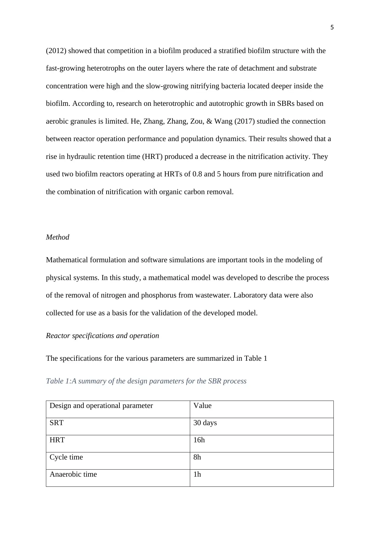
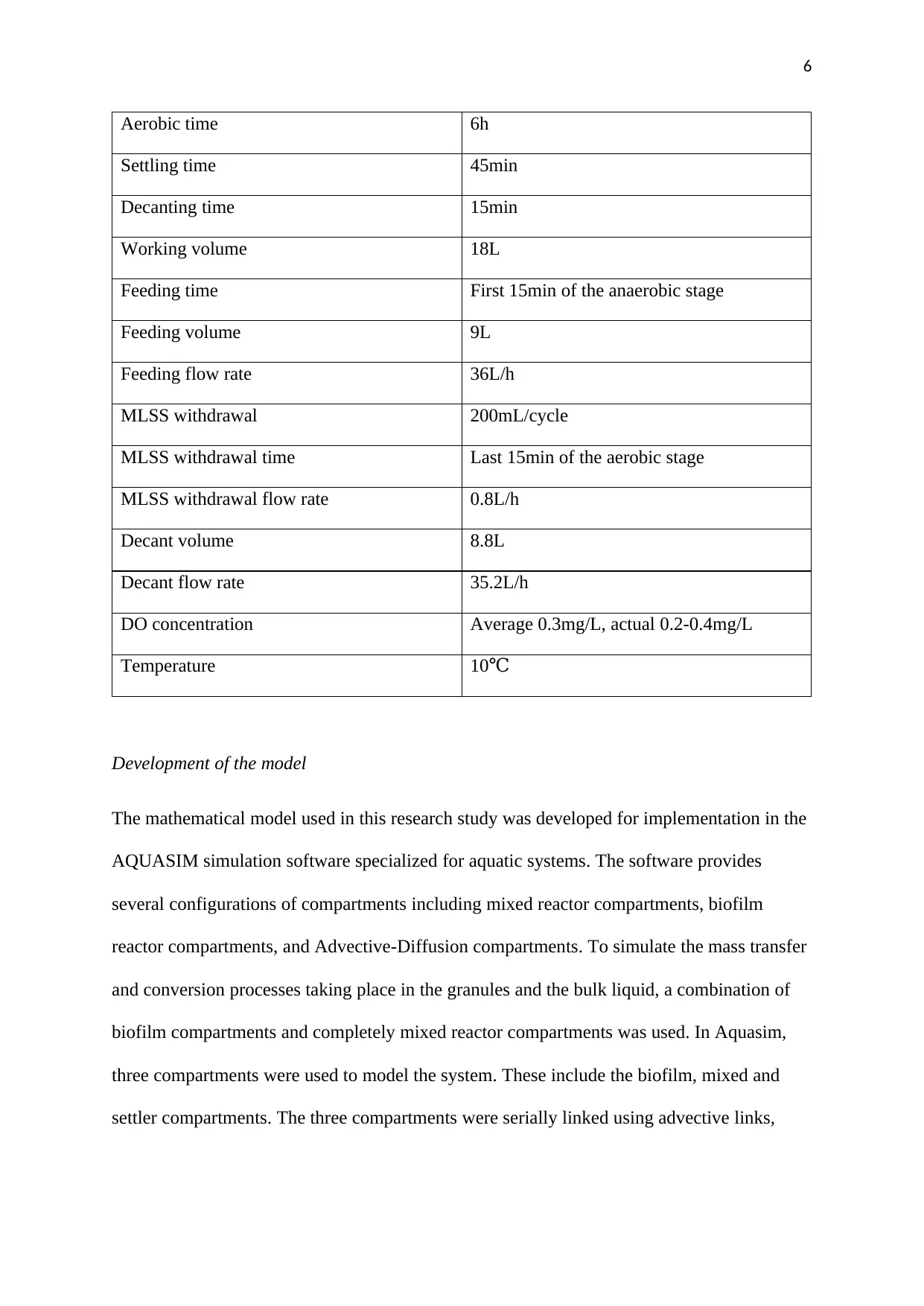
The specifications for the various parameters are summarized in Table 1
Table 1:A summary of the design parameters for the SBR process
Design and operational parameter Value
SRT 30 days
HRT 16h
Cycle time 8h
Anaerobic time 1h
6
Aerobic time 6h
Settling time 45min
Decanting time 15min
Working volume 18L
Feeding time First 15min of the anaerobic stage
Feeding volume 9L
Feeding flow rate 36L/h
MLSS withdrawal 200mL/cycle
MLSS withdrawal time Last 15min of the aerobic stage
MLSS withdrawal flow rate 0.8L/h
Decant volume 8.8L
Decant flow rate 35.2L/h
DO concentration Average 0.3mg/L, actual 0.2-0.4mg/L
Temperature 10℃
Development of the model
The mathematical model used in this research study was developed for implementation in the
AQUASIM simulation software specialized for aquatic systems. The software provides
several configurations of compartments including mixed reactor compartments, biofilm
reactor compartments, and Advective-Diffusion compartments. To simulate the mass transfer
and conversion processes taking place in the granules and the bulk liquid, a combination of
biofilm compartments and completely mixed reactor compartments was used. In Aquasim,
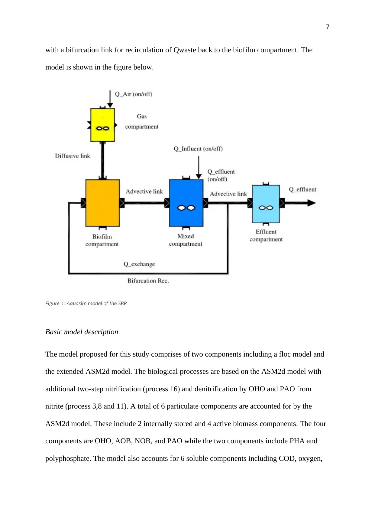
three compartments were used to model the system. These include the biofilm, mixed and
settler compartments. The three compartments were serially linked using advective links,
⊘ This is a preview!⊘
Do you want full access?
Subscribe today to unlock all pages.

Trusted by 1+ million students worldwide
7
with a bifurcation link for recirculation of Qwaste back to the biofilm compartment. The
model is shown in the figure below.
Figure 1: Aquasim model of the SBR
Basic model description
The model proposed for this study comprises of two components including a floc model and
the extended ASM2d model. The biological processes are based on the ASM2d model with
additional two-step nitrification (process 16) and denitrification by OHO and PAO from
nitrite (process 3,8 and 11). A total of 6 particulate components are accounted for by the
ASM2d model. These include 2 internally stored and 4 active biomass components. The four
components are OHO, AOB, NOB, and PAO while the two components include PHA and
polyphosphate. The model also accounts for 6 soluble components including COD, oxygen,
Paraphrase This Document
Need a fresh take? Get an instant paraphrase of this document with our AI Paraphraser
8
phosphorus, nitrate, nitrite, and ammonia. The floc model is based on that used by Henze et
al. (2008).
Extended ASM2d
The model consists of a total of 18 processes. VFAs in the influent are consumed by PAO
under anaerobic conditions to store as PHA. VFAs, PHA act as carbon sources for the two
types of bacteria for denitrification, OHO, and PAO respectively. For denitrification, nitrite
or nitrate can act as the electron acceptor. It is also possible to store phosphorous as
polyphosphate through PAO in anoxic conditions. The carbon needed by OHO and PAO for
growth can be sourced from VFAs and PHA respectively. For nitrification, AOB and NOB
can utilize ammonia and nitrite respectively as the electron donors. The model also includes
the endogenous respirations for OHO AOB, NOB, and PAO. The kinetics and stoichiometry
for the model are derived from (De Kreuk et al., 2007; Henze et al., 2000; Jubany Güell,
2007; Wiesmann, 1994). The stoichiometric matrix, process rate equations, and kinetic
parameters are presented in the appendix in tables 1 and 2.
The floc model
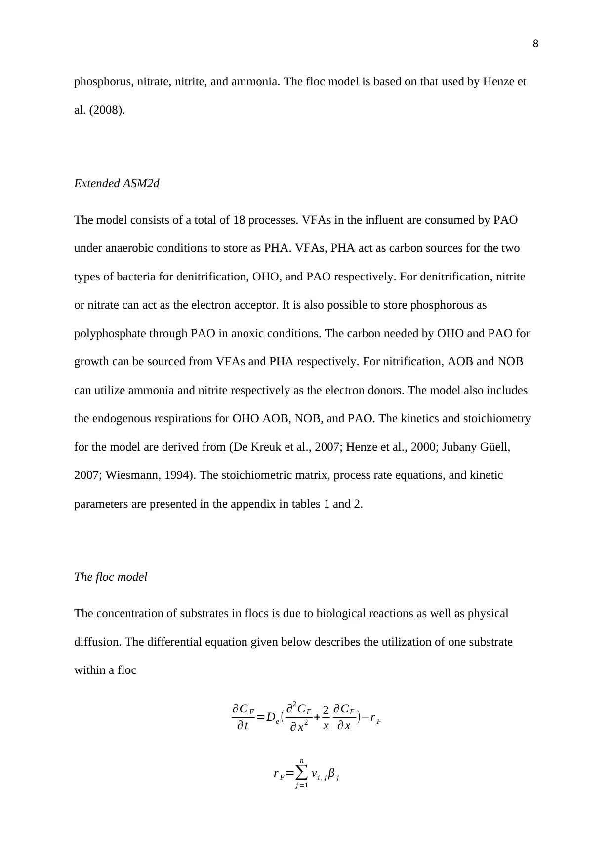
The concentration of substrates in flocs is due to biological reactions as well as physical
diffusion. The differential equation given below describes the utilization of one substrate
within a floc
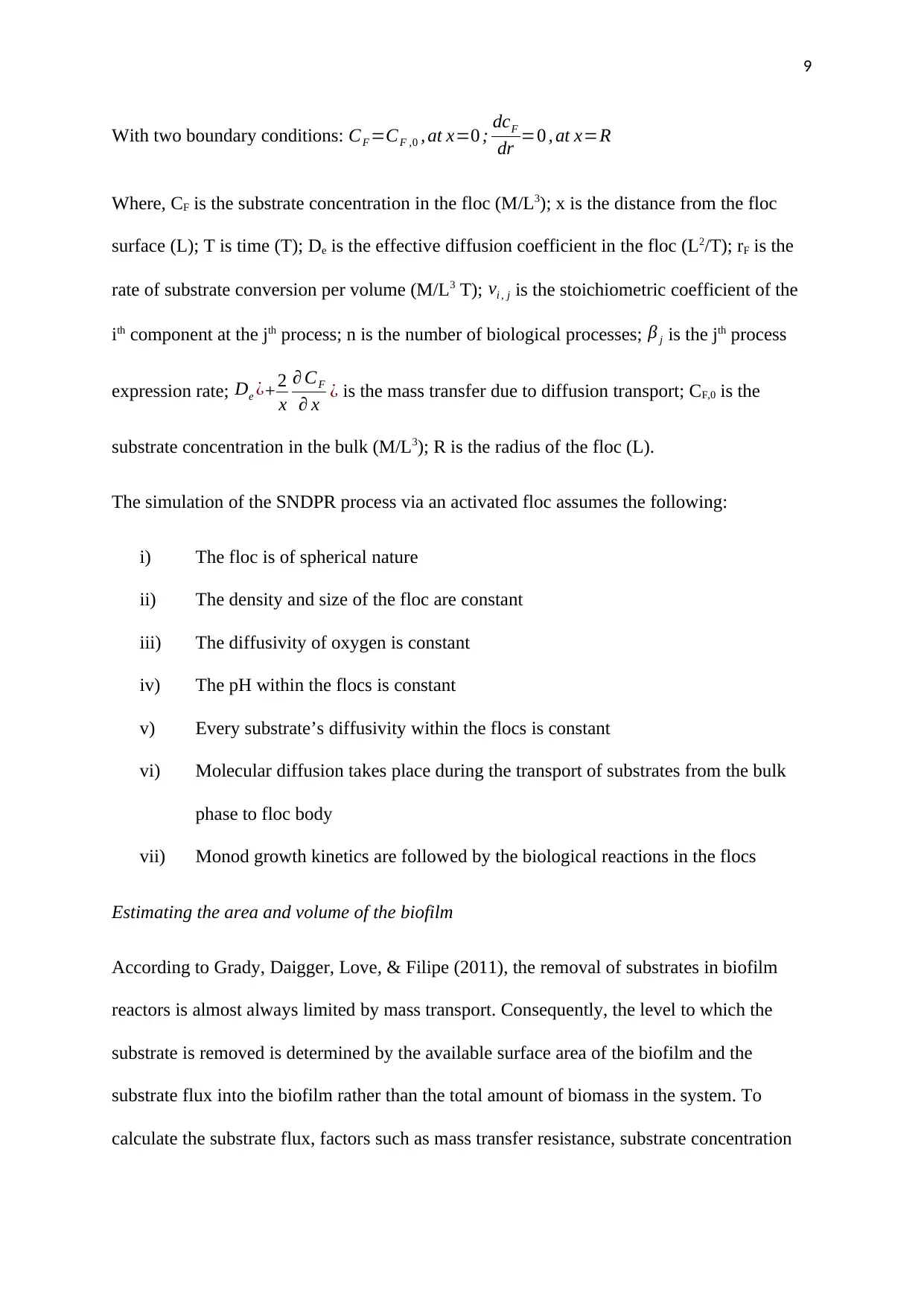
∂C F
∂ t =De ( ∂2 CF
∂ x2 + 2
x
∂CF
∂ x )−r F
r F =∑
j =1
n
vi , j β j
9
With two boundary conditions: CF =CF ,0 , at x=0 ; dcF
dr =0 , at x=R
Where, CF is the substrate concentration in the floc (M/L3); x is the distance from the floc
surface (L); T is time (T); De is the effective diffusion coefficient in the floc (L2/T); rF is the
rate of substrate conversion per volume (M/L3 T); vi , j is the stoichiometric coefficient of the
ith component at the jth process; n is the number of biological processes; β j is the jth process
expression rate; De ¿+ 2
x
∂ CF
∂ x ¿ is the mass transfer due to diffusion transport; CF,0 is the
substrate concentration in the bulk (M/L3); R is the radius of the floc (L).
The simulation of the SNDPR process via an activated floc assumes the following:
i) The floc is of spherical nature
ii) The density and size of the floc are constant
iii) The diffusivity of oxygen is constant
iv) The pH within the flocs is constant
v) Every substrate’s diffusivity within the flocs is constant
vi) Molecular diffusion takes place during the transport of substrates from the bulk
phase to floc body
vii) Monod growth kinetics are followed by the biological reactions in the flocs
Estimating the area and volume of the biofilm
According to Grady, Daigger, Love, & Filipe (2011), the removal of substrates in biofilm
reactors is almost always limited by mass transport. Consequently, the level to which the
substrate is removed is determined by the available surface area of the biofilm and the
substrate flux into the biofilm rather than the total amount of biomass in the system. To
calculate the substrate flux, factors such as mass transfer resistance, substrate concentration
⊘ This is a preview!⊘
Do you want full access?
Subscribe today to unlock all pages.

Trusted by 1+ million students worldwide
10
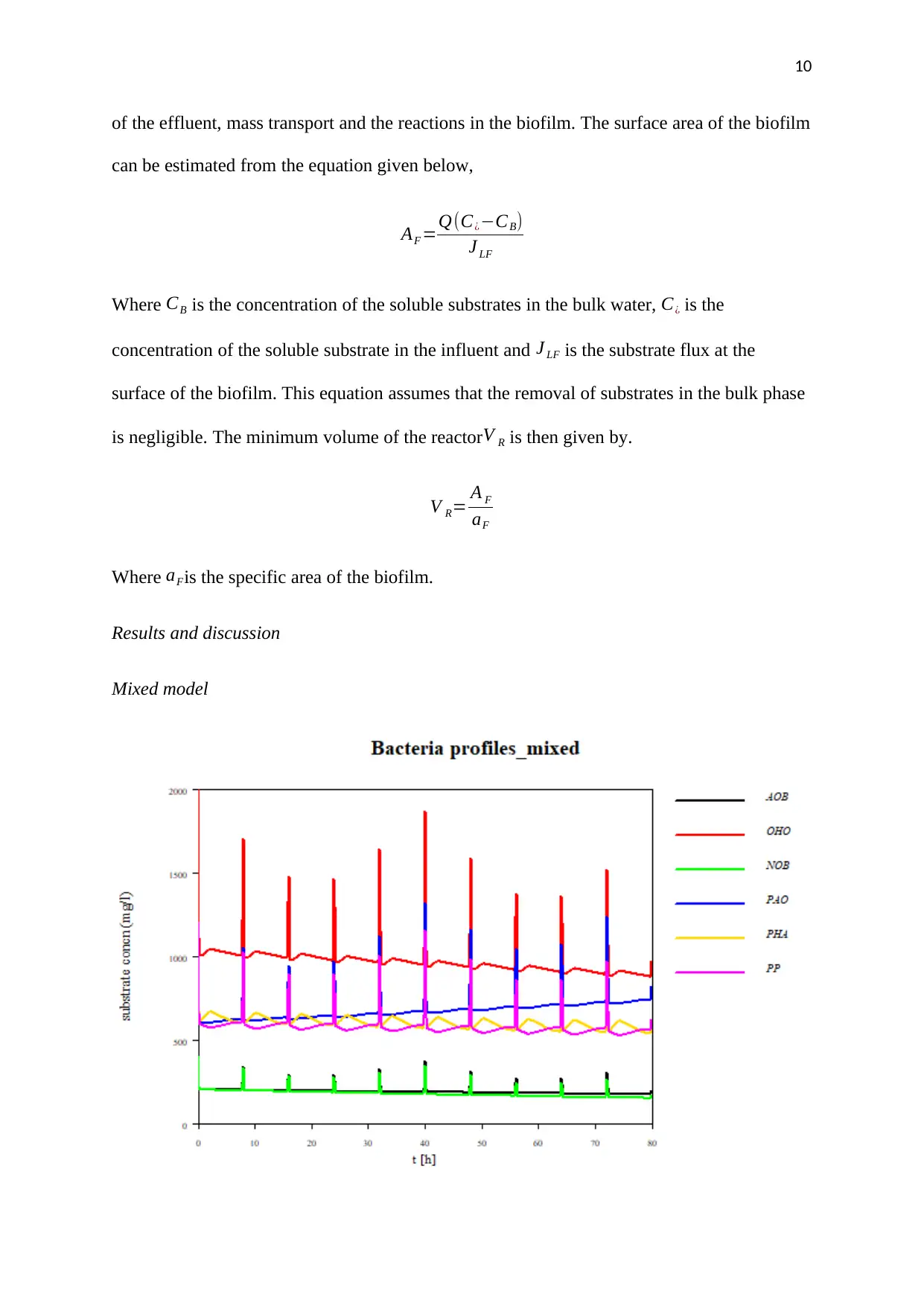
of the effluent, mass transport and the reactions in the biofilm. The surface area of the biofilm
can be estimated from the equation given below,
AF =Q(C¿−CB)
J LF
Where CB is the concentration of the soluble substrates in the bulk water, C¿ is the
concentration of the soluble substrate in the influent and J LF is the substrate flux at the
surface of the biofilm. This equation assumes that the removal of substrates in the bulk phase
is negligible. The minimum volume of the reactorV R is then given by.
V R= A F
aF
Where aFis the specific area of the biofilm.
Results and discussion
Mixed model
Paraphrase This Document
Need a fresh take? Get an instant paraphrase of this document with our AI Paraphraser
11
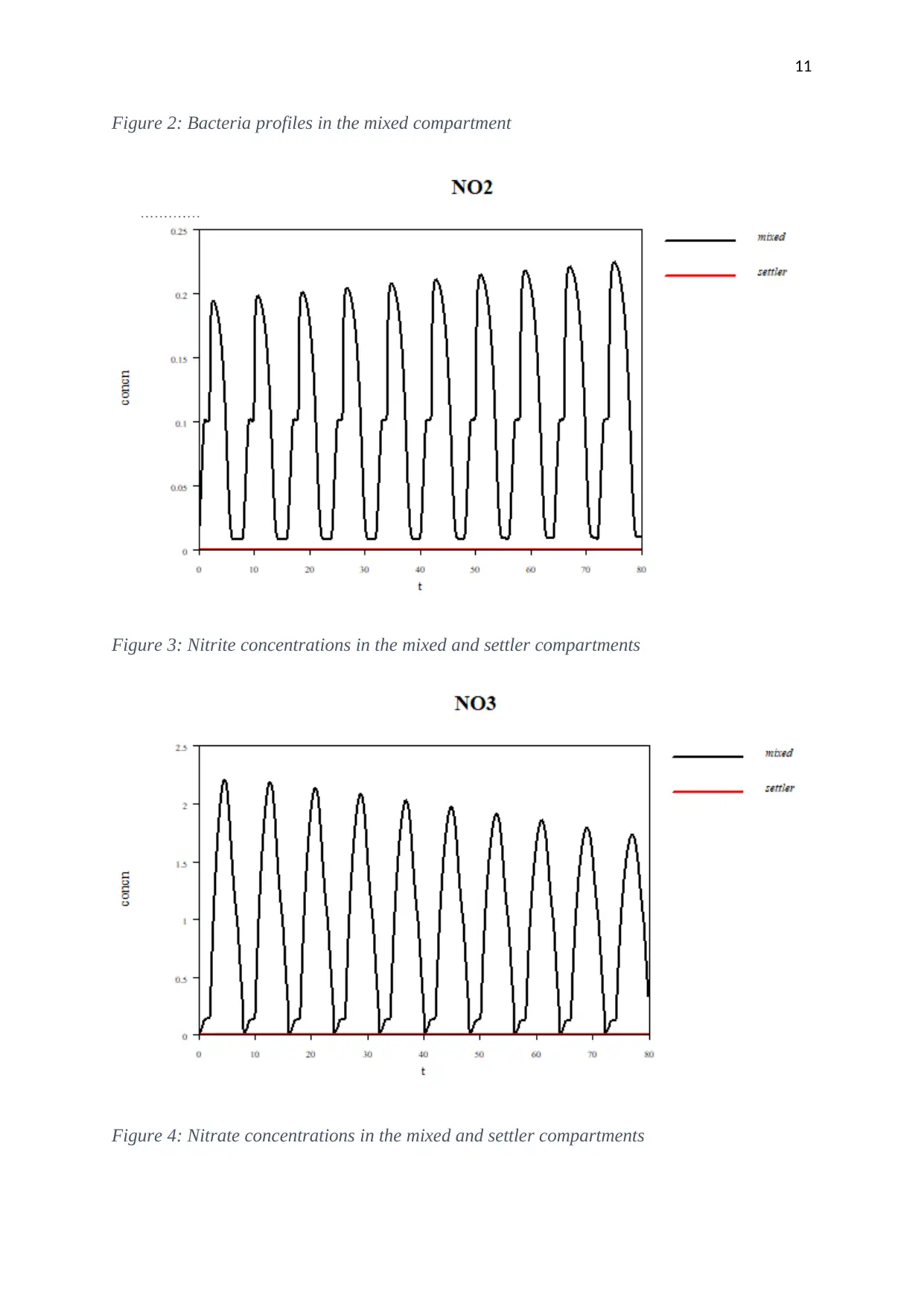
Figure 2: Bacteria profiles in the mixed compartment
Figure 3: Nitrite concentrations in the mixed and settler compartments
Figure 4: Nitrate concentrations in the mixed and settler compartments
Figure 2: Bacteria profiles in the mixed compartment
Figure 3: Nitrite concentrations in the mixed and settler compartments
Figure 4: Nitrate concentrations in the mixed and settler compartments
12
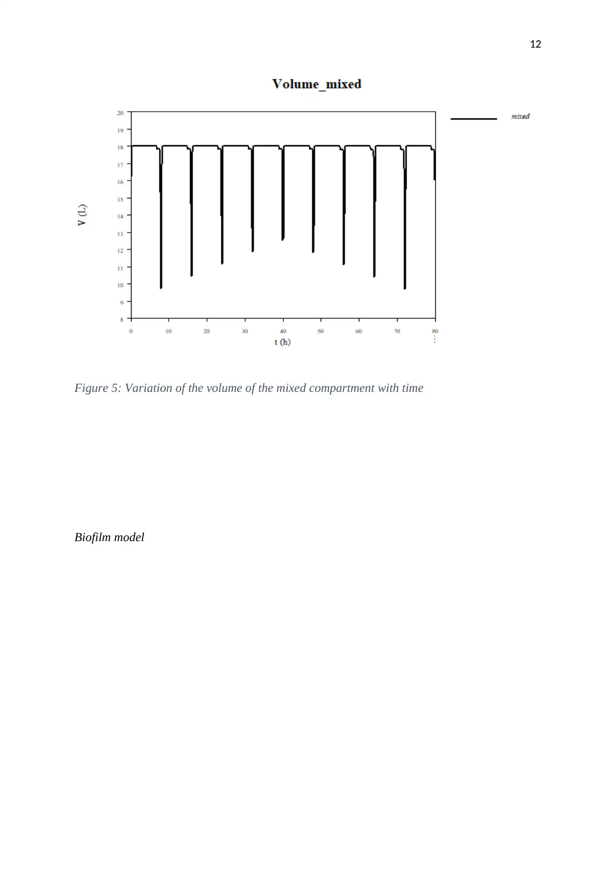
Figure 5: Variation of the volume of the mixed compartment with time
Biofilm model
Figure 5: Variation of the volume of the mixed compartment with time
Biofilm model
⊘ This is a preview!⊘
Do you want full access?
Subscribe today to unlock all pages.

Trusted by 1+ million students worldwide
1 out of 29
Your All-in-One AI-Powered Toolkit for Academic Success.
+13062052269
info@desklib.com
Available 24*7 on WhatsApp / Email
![[object Object]](/_next/static/media/star-bottom.7253800d.svg)
Unlock your academic potential
Copyright © 2020–2025 A2Z Services. All Rights Reserved. Developed and managed by ZUCOL.
