Teesside University: Programmable Logic Controllers Assignment
VerifiedAdded on 2022/08/12
|18
|2302
|21
Homework Assignment
AI Summary
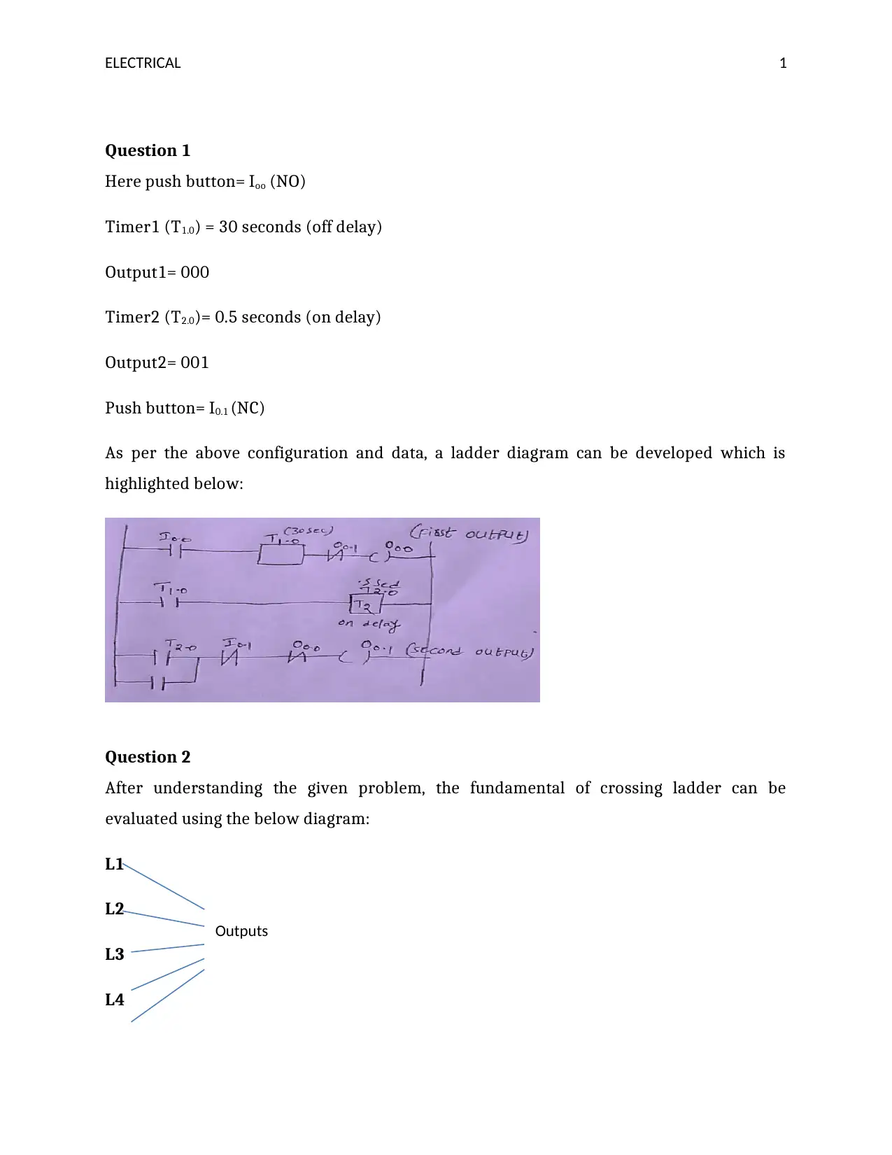
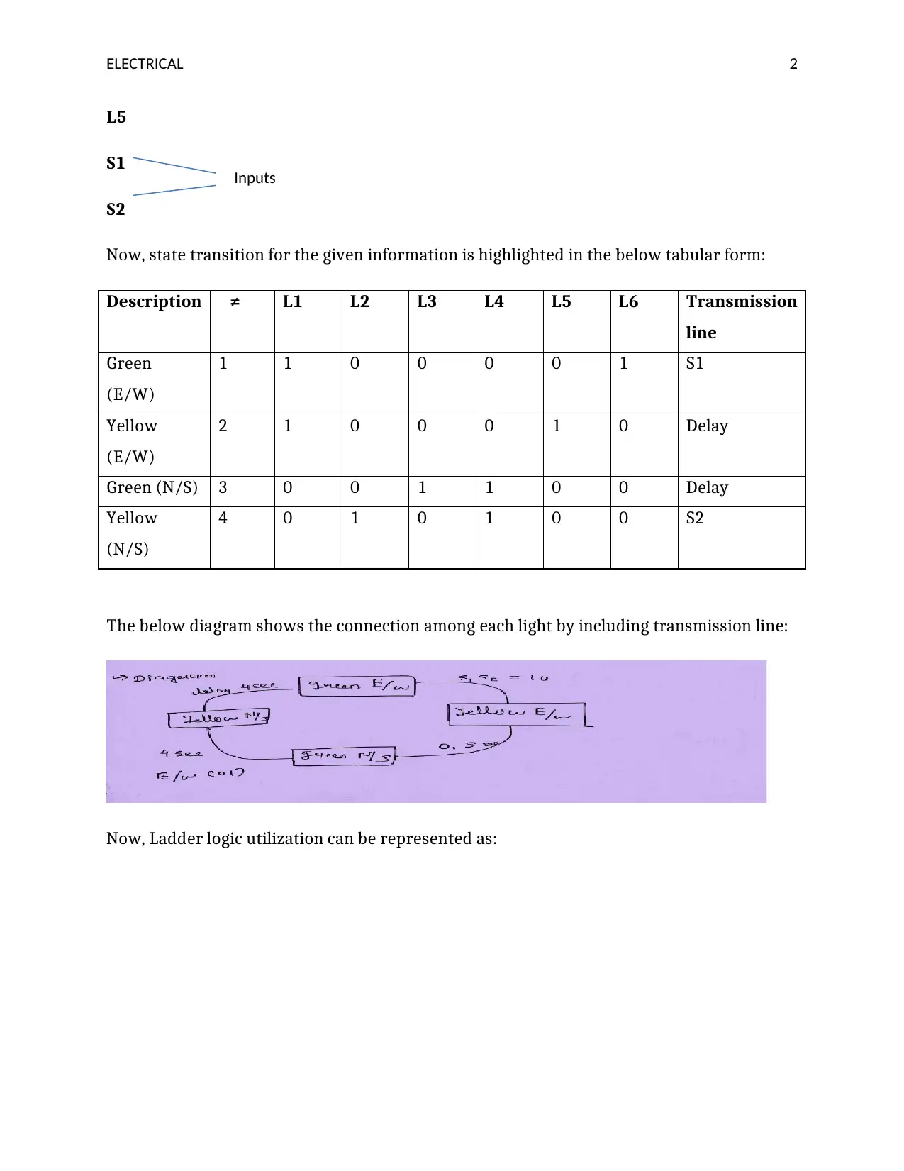
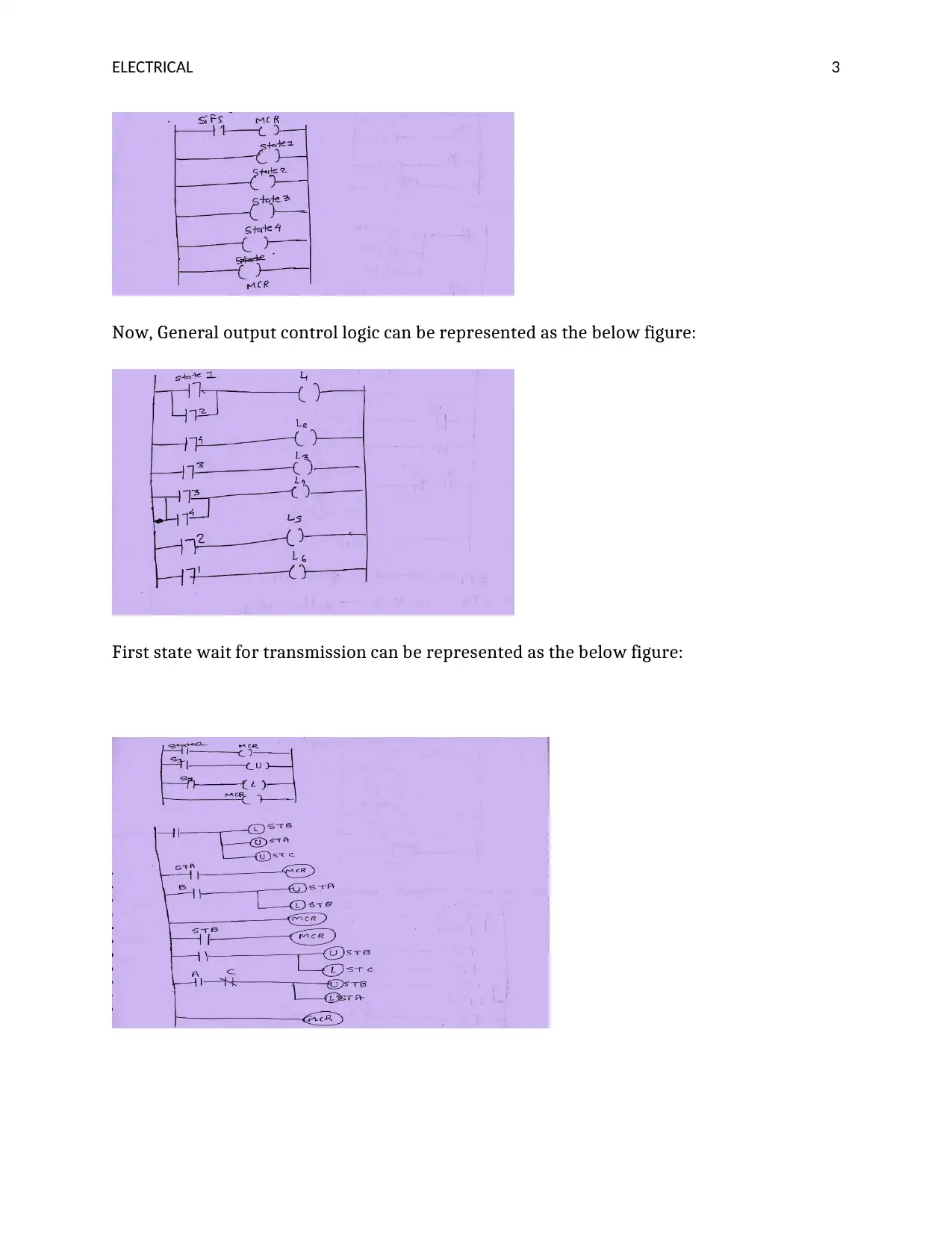
This document presents a complete solution to a Programmable Logic Controllers (PLC) assignment, addressing multiple facets of PLC programming and related technologies. The solution begins with a ladder diagram implementation based on given specifications, including timer functionalities and output controls. It then explores state transition diagrams and boolean expressions for traffic light control systems. The assignment further delves into shift register applications, detailing the control of relays using 8-bit shift registers. Additionally, the solution analyzes A/D conversion, calculating bit resolutions and converting decimal to hexadecimal values. The document also covers multiplexing techniques (FDM, TDM, WDM, and CDM), and the application of these techniques in communication systems. Finally, the assignment addresses circuit analysis, LAN applications, and the functionalities of RTUs, EIA-422, and IEEE-488 standards. The solution incorporates references to support the concepts discussed.
1 out of 18


Your All-in-One AI-Powered Toolkit for Academic Success.
+13062052269
info@desklib.com
Available 24*7 on WhatsApp / Email
![[object Object]](/_next/static/media/star-bottom.7253800d.svg)
Copyright © 2020–2026 A2Z Services. All Rights Reserved. Developed and managed by ZUCOL.