Teesside University PLC Programming Assignment Solution
VerifiedAdded on 2023/06/09
|8
|1114
|130
Homework Assignment
AI Summary
This document presents a comprehensive solution to a Programmable Logic Controllers (PLC) assignment. It addresses various scenarios, including the operation of alarm systems, lamp tests, and parking space sensors. The assignment utilizes ladder diagrams to illustrate the logic and control sequences. Case studies are provided to analyze different situations, such as the response to an alarm condition and the behavior of a parking space monitoring system. The solution includes detailed explanations of the logic behind each scenario, incorporating the use of contactors, inputs, and outputs. The document also features a ladder diagram for a parking space sensor system, explaining how the AND gate and inverters are used to indicate the availability of parking spaces. The assignment is well-structured, providing a thorough understanding of PLC programming and its applications in industrial control systems.
Running head: PROGRAMMABLE LOGIC CONTROLLERS 0
Paper Title Capitalized and Centered
Name of Student
Institution Affiliation
Paper Title Capitalized and Centered
Name of Student
Institution Affiliation
Paraphrase This Document
Need a fresh take? Get an instant paraphrase of this document with our AI Paraphraser
PROGRAMMABLE LOGIC CONTROLLERS 2
Question one
Case 1
If the operator press the ACCEPT button when the plant is alarm the audible alarm stop and the
flashing Amber light changes to Permanently ON (Bolton, Programmable Logic Controllers,
2016).
Ladder Diagram
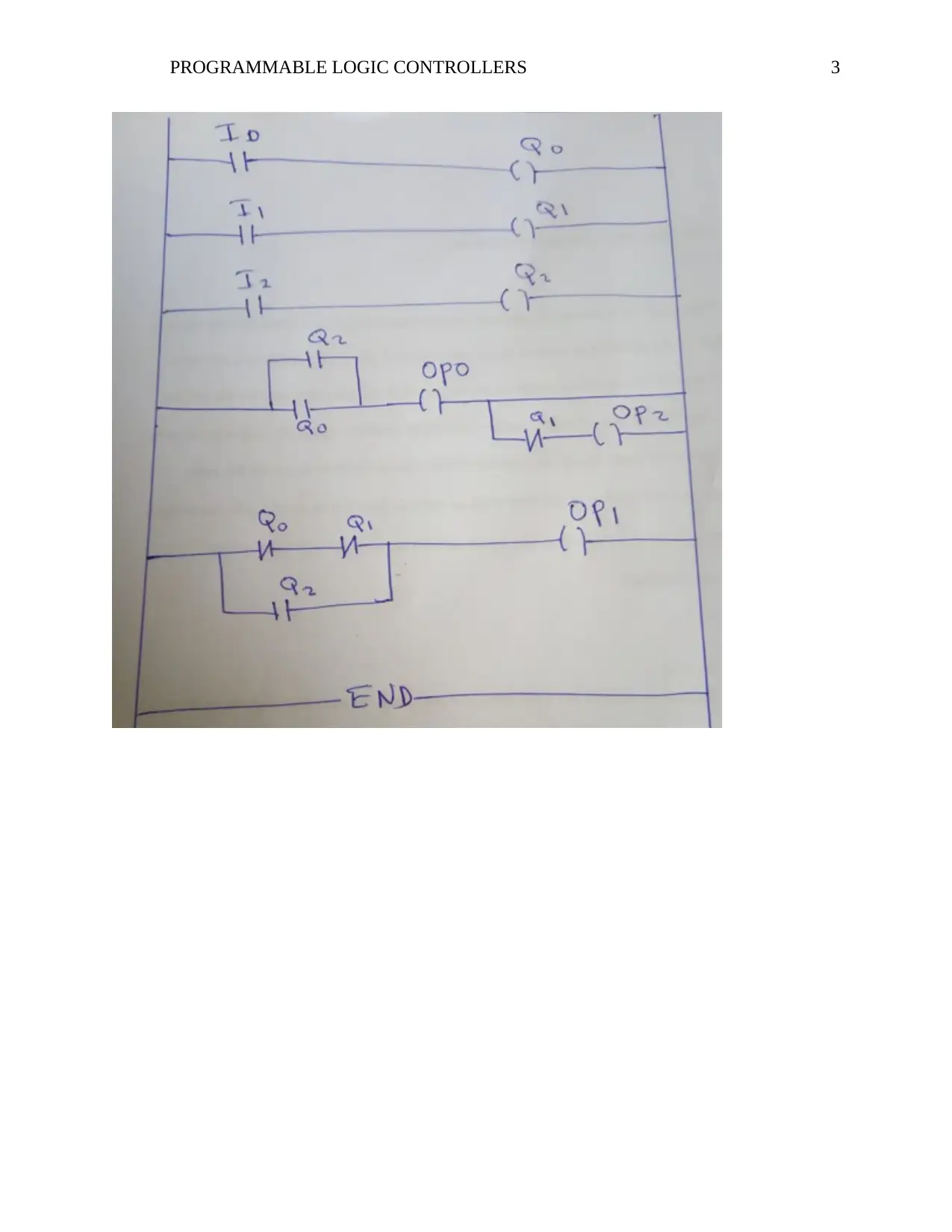
In this case we will have to use three contactors as outputs these are namely (Q 0, Q1 and Q2)
and three inputs that is ( I0, I1, and I2 ) (Clements, 2016).
PROGRAMMABLE LOGIC CONTROLLERS 3
⊘ This is a preview!⊘
Do you want full access?
Subscribe today to unlock all pages.

Trusted by 1+ million students worldwide

PROGRAMMABLE LOGIC CONTROLLERS 4
Conclusion from above scenario
When the ACCEPT button (IP1) is pressed and when the plant is in alarm condition then the
(OP0) will glow and alarm stop therefore we have to connect the Normally closed contact for Q1
to the OP2
Case 2
If the plat drops out of the alarm condition before the ACCEPT button is pressed, the panel will
show a flashing green light (Committee, 2015). The audible alarm and the amber light will go
OFF
- If the plant drop out of the alarm system (Alarm off )
- Before the ACCEPT button ( accept off)
- Therefore the green light will indicate OFF and the OP0 and OP1 will be OFF.
Case 3
If the ACCEPT button was pressed when the plant is healthy as in 2 above the flashing green
light will go OFF. If the ACCEPT button is ON and the plant healthy (alarm off) then green light
OFF.
Case 4
Paraphrase This Document
Need a fresh take? Get an instant paraphrase of this document with our AI Paraphraser
PROGRAMMABLE LOGIC CONTROLLERS 5
There should be a lamp test (the button which when pressed will light all lamps and sound the
audible alarm).
Lamp test. The button ON then the OP0, OP1 and OPQ will also be ON.
We will have to note that, it is started by whatever we can through use of the three contactors as
in the problem.
Question two
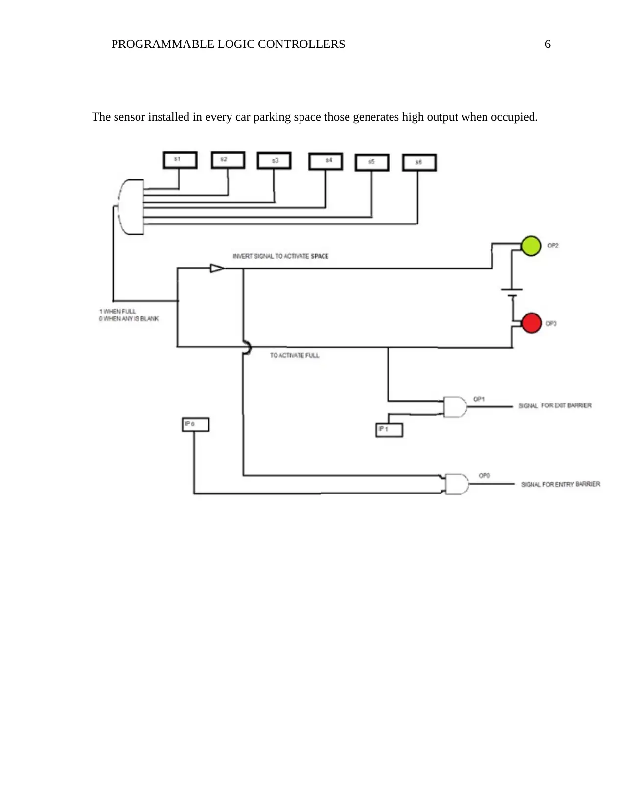
The logic ladder diagram can be explained as below;
- The AND gate will gather all the input from 6 parking space sensors and then generates a
1 when completely filled if not it will gives a 0.
- Inverting the signal makes the green light to glow indicating available spaces and direct
interpretation glows red indicating no parking space available (Committee, 2015).
- OP 1 signal generated after ANDing the IP1 sensor signal and gives the output from a
very large AND gate.
- OP0 signal generated after ANDing the IP0 signal the output from large AND gate. The
ladder diagram is shown in the diagram below;
PROGRAMMABLE LOGIC CONTROLLERS 6
The sensor installed in every car parking space those generates high output when occupied.
The sensor installed in every car parking space those generates high output when occupied.
⊘ This is a preview!⊘
Do you want full access?
Subscribe today to unlock all pages.

Trusted by 1+ million students worldwide
PROGRAMMABLE LOGIC CONTROLLERS 7
References
Ahmed, M. (2011). PLC (3rd ed.). London: Springer.
Bolton, W. (2015). Programmable Logic Controllers. Chicago: IEEE.
Bolton, W. (2016). Programmable Logic Controllers. Leicester: Elsevier.
Britain, G. (2013). Somerfield Plc and Wm Morrison Supermarkets Plc: A Report on the
Acquisition by Somerfield Plc of 115 Stores from Wm Morrison Supermarkets Plc. Hull:
The Stationery Office.
Cemic, L. (2015). Automation using PLC (2nd ed.). Leicester: Springer Science & Business
Media.
Charria, O. (2010). Fundamentals of Programmable Logic Controllers and Ladder Logic.
Hawaii: IEEE.
Clements, K. (2016). The PLC Workbook: Programmable Logic Controllers Made Easy.
Florida: Prentice Hall.
Committee, G. B. (2015). Parking Policy and Enforcement: Seventh Report of Session 2005-06.
London: CRC.
Dahm, K. (2014). PLC (3rd ed.). Chicago: Cengage Learning.
GREEN, C. (2014). Learn How to Program and Troubleshoot Ladder Logic. Hull: CRC.
Kamel, K. (2013). Programmable Logic Controllers: Industrial Control. Cairo: Haiver .
Kamen, E. W. (2010). Industrial Controls and Manufacturing. Hull: Elsevier.
Kent, G. (2014). PLC Ladder Diagram Programming Reference. Florida: entral Queensland
University, Department of Electrical Engineering.
Knopf, C. (2011). Modeling, Analysis and Industrial control using PLC (4th ed.). Manchester:
John Wiley & Sons.
Letcher, T. (2017). PLC (1st ed.). Stoke: Royal Society of Chemistry.
Lvov, B. (2012). PLC :Industrial control (3rd ed.). Hull: Springer Science & Business Media.
Mbadi, J. (2010). PLC (2nd ed.). Hull: CRC.
Paraphrase This Document
Need a fresh take? Get an instant paraphrase of this document with our AI Paraphraser
PROGRAMMABLE LOGIC CONTROLLERS 8
Mehra, R. (2011). PLCs & SCADA : Theory and Practice. New Delhi: CRC.
Petruzella, F. (2014). Programmable Logic Controllers. Beijing: CRC.
Rao, K. (2010). Ladder Programming of PLC (1st ed.). Hull: CUP Archive,.
Rehg, J. A. (2017). Programmable Logic Controllers. Chicago: Prentice Hall.
Ridley, J. (2014). Mitsubishi FX Programmable Logic Controllers: Applications and
Programming. Hull: Elsevier.
Rohner, P. (2016). Automation with Programmable Logic Controllers. New Delhi: UNSW Press.
Sato, N. (2014). Programming of PLC for Engineers (3rd ed.). London: Elsevier.
Tremaine, P. (2012). PLC controllers (2nd ed.). Hull: NRC Research Press.
Tsao, J. (2012). Ladder Diagram in PLC (2nd ed.). Manchetser: Academic Press.
Webb, J. (2011). Programmable Logic Controllers: Principles and Applications. Stoke : Heiver.
Wilson, H. (2014). Major Companies of Europe 1990/91: Volume 2 Major Companies of the
United Kingdom using PLC controllers . London: IEEE.
Wohlfarth, C. (2016). CRC Handbook for PLC (4th ed.). Manchester: CRC Press.
1 out of 8
Your All-in-One AI-Powered Toolkit for Academic Success.
+13062052269
info@desklib.com
Available 24*7 on WhatsApp / Email
![[object Object]](/_next/static/media/star-bottom.7253800d.svg)
Unlock your academic potential
Copyright © 2020–2025 A2Z Services. All Rights Reserved. Developed and managed by ZUCOL.


