Comprehensive UML Diagrams and Java Implementation for Online Retail
VerifiedAdded on 2021/02/19
|20
|2787
|114
Project
AI Summary
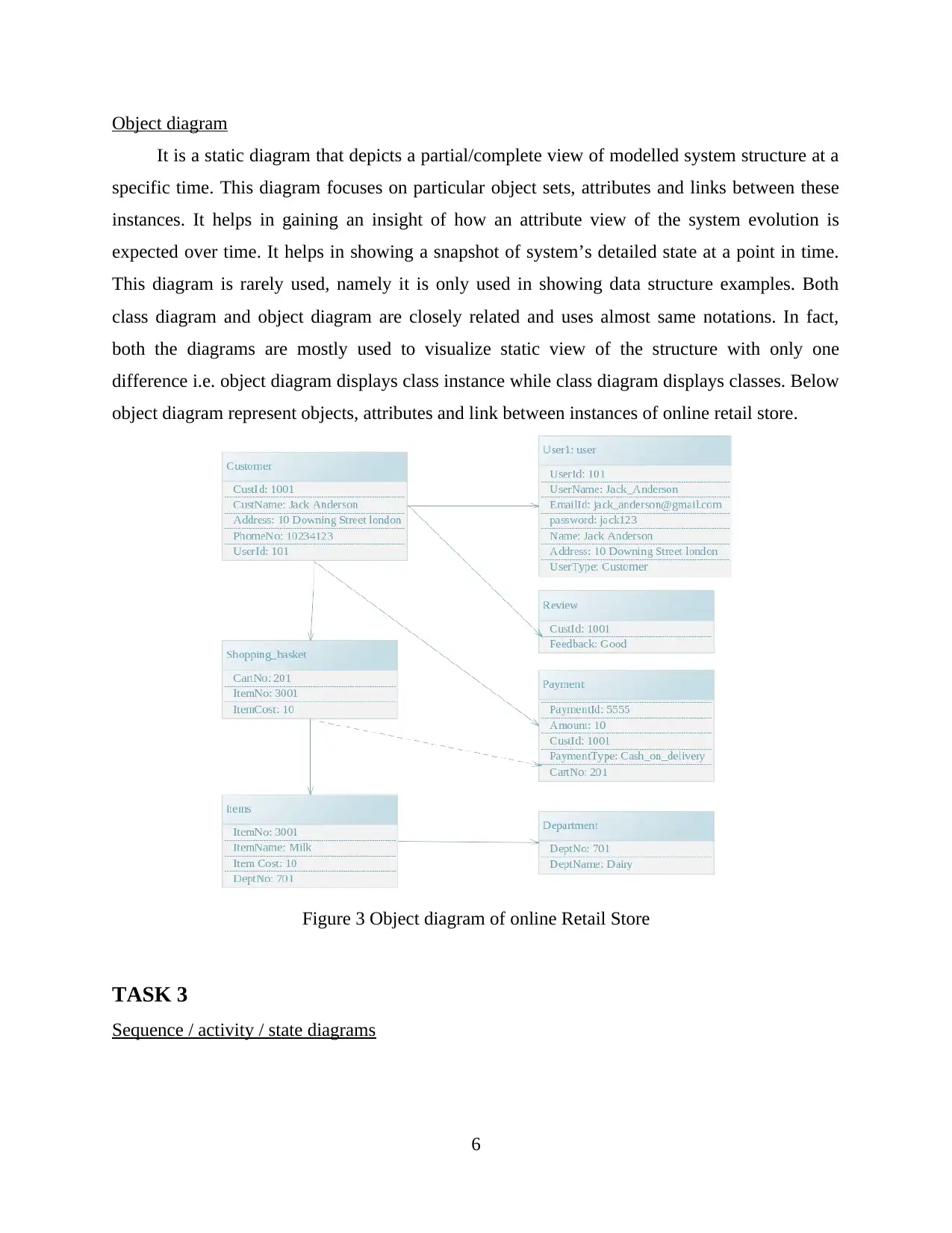
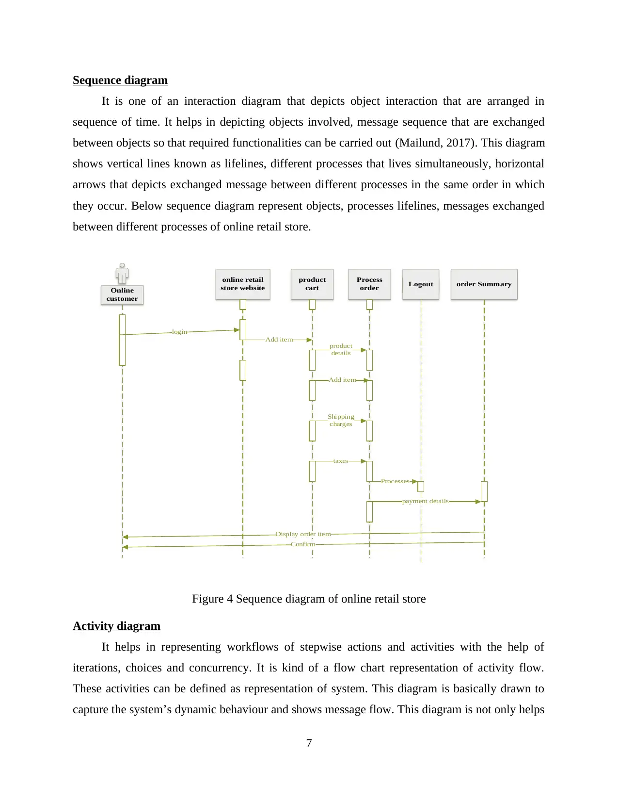
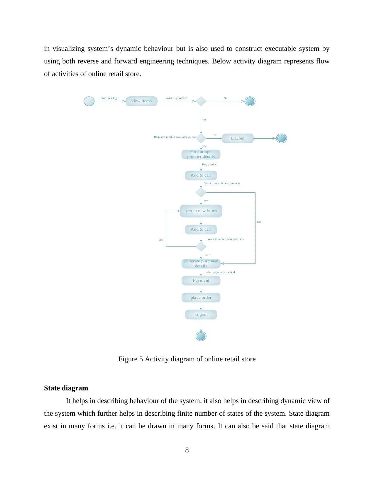
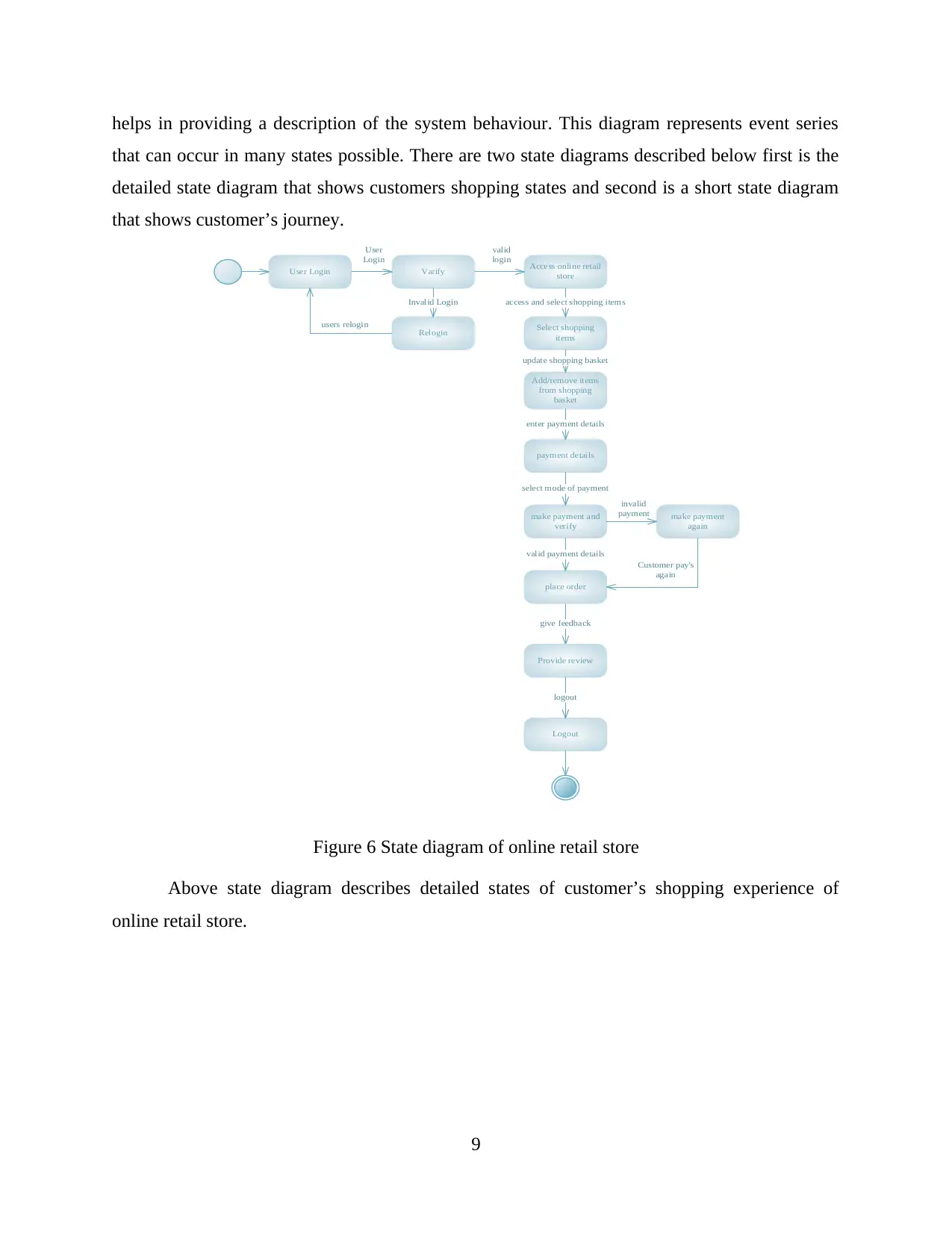
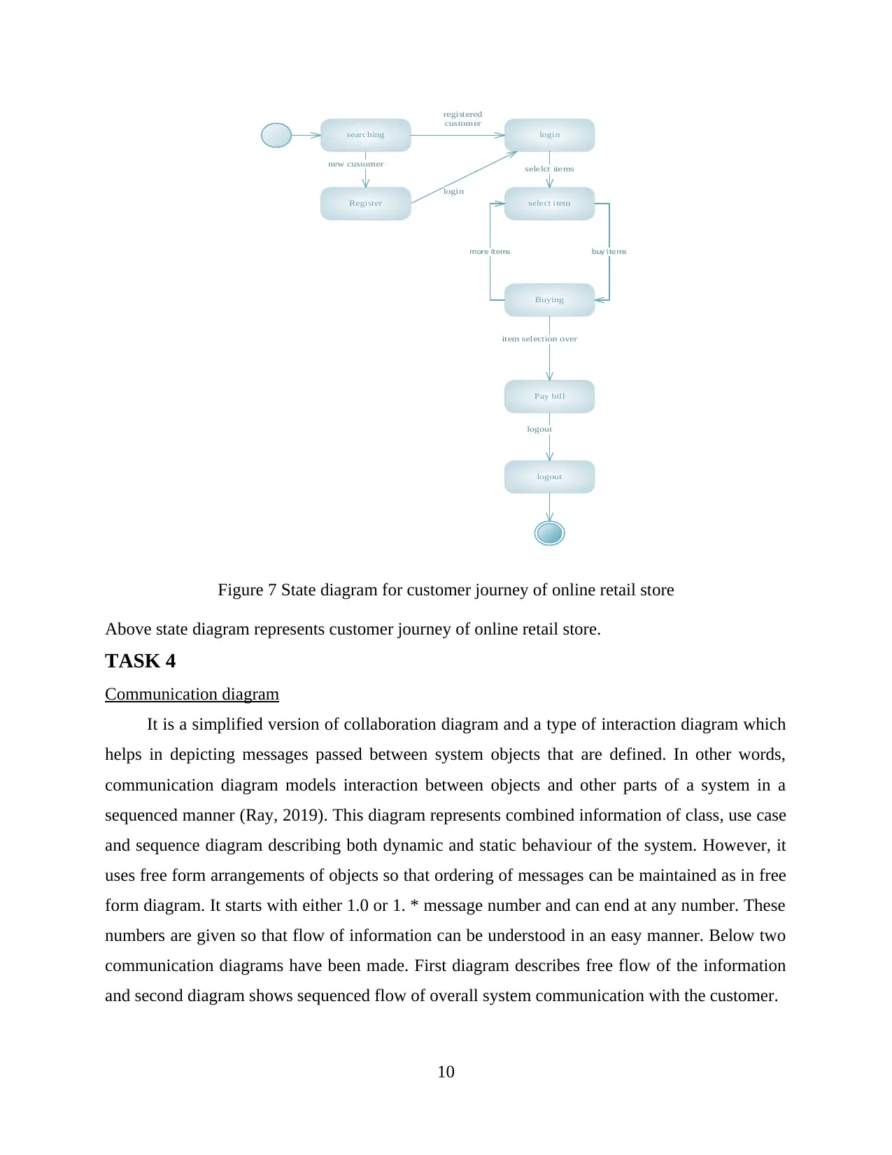
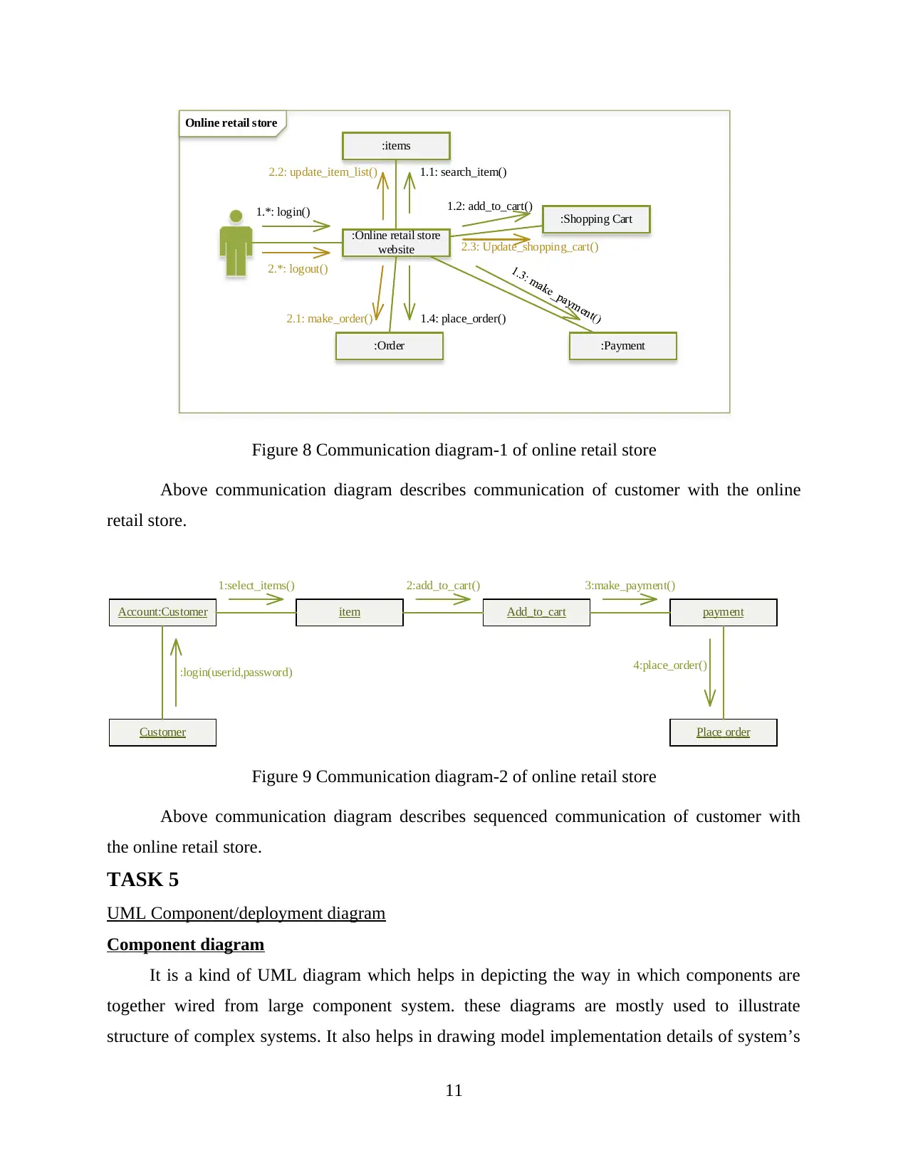
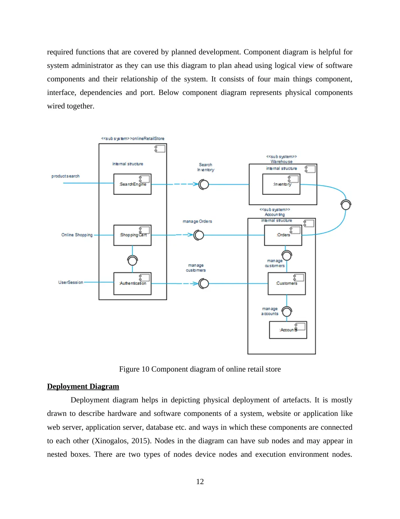
This assignment provides a comprehensive analysis of an online retail store system using Unified Modeling Language (UML) diagrams and Java programming. The project begins with a case study outlining the requirements for an online retail platform, where customers can browse, select, and order items. The solution then presents various UML diagrams, including use case, class, object, sequence, activity, state, component, and deployment diagrams, to model the system's structure, behavior, and interactions. Each diagram is explained with its components and purpose in the context of the online retail store. Furthermore, the assignment includes Java code examples demonstrating key object-oriented programming (OOP) concepts such as inheritance, class interactions, abstract classes, and interface implementations. The Java code is designed to illustrate how these concepts can be applied to create a functional and scalable online retail system. The assignment aims to provide a clear understanding of system modeling and software design using UML and Java, offering a practical approach to developing an online retail platform.

PROGRAMMING
1
1
Paraphrase This Document
Need a fresh take? Get an instant paraphrase of this document with our AI Paraphraser

2

INTRODUCTION
UML diagrams are type of diagrams that are used for modelling and documenting
software’s, applications etc. These diagrams help in understanding a system, its processes and
functionalities in a better manner. UML diagrams helps in understanding a system in a better
manner and if there are any kind of flaws or errors within the system then it can be understood in
a better manner. These diagrams also help the programmer to understand all the functionalities of
the system and the way in which they interact with each other. This assignment will help in
describing various kinds of UML diagrams based on a case study in which a retail store wants to
implement an online retail store for their customer’s where customers will be able to place orders
through website. This assignment will also focus on java programs which will help in
understanding inheritance concept, interaction between class methods, abstract class and
interface implementation in java.
TAKS 1
Use case diagram
Use case diagram can be defined as a simplest way of representation of system and user’s
interaction (O'Hara and Slavin, 2019). This diagram shows relationship between users and
different use cases involved. In other words, this diagram can help in identifying different types
of system users and functions used by them. Below use case diagram represent actors and use
cases of online retail store.
3
⊘ This is a preview!⊘
Do you want full access?
Subscribe today to unlock all pages.

Trusted by 1+ million students worldwide

Figure 1 use case diagram of online retail store
Above use case diagram consist of two main actors: first is Admin and second is a customer.
Admin has four main functions: maintenance of item details i.e. which item is available and
which is not, update items that are available for home delivery, create reports of ordered items.
Customer’s also have access to four main functionalities of the system that are: browsing of
online store, selecting items for shopping, place order of selected items and pay for them and
lastly provide feedback to online retail store about their shopping experience.
4
Paraphrase This Document
Need a fresh take? Get an instant paraphrase of this document with our AI Paraphraser

TASK 2
Class Diagram
It is a static structure diagram which helps in describing the overall structure of the system
by showing various attributes, system classes, relationship between them. Class diagram are said
to be the main building blocks of OOM. It is also used as conceptual of application structures
modelling and it is also used for detailed modelling as well as model translating into
programming code (Jansen, 2015). Classes in this diagram represent both interactions in
applications, main elements and classes to be programmed. Below class diagram represent
classes, attributes and relationships of online retail store.
Figure 2 Class Diagram of online Retail Store
Above class diagram consist of seven classes that are: user, customer, shopping basket,
items, department, payment and review. Each class has its own attributes and all the classes are
inter related with each other i.e. each class has come relation with other classes.
5

Object diagram
It is a static diagram that depicts a partial/complete view of modelled system structure at a
specific time. This diagram focuses on particular object sets, attributes and links between these
instances. It helps in gaining an insight of how an attribute view of the system evolution is
expected over time. It helps in showing a snapshot of system’s detailed state at a point in time.
This diagram is rarely used, namely it is only used in showing data structure examples. Both
class diagram and object diagram are closely related and uses almost same notations. In fact,
both the diagrams are mostly used to visualize static view of the structure with only one
difference i.e. object diagram displays class instance while class diagram displays classes. Below
object diagram represent objects, attributes and link between instances of online retail store.
Figure 3 Object diagram of online Retail Store
TASK 3
Sequence / activity / state diagrams
6
⊘ This is a preview!⊘
Do you want full access?
Subscribe today to unlock all pages.

Trusted by 1+ million students worldwide

Sequence diagram
It is one of an interaction diagram that depicts object interaction that are arranged in
sequence of time. It helps in depicting objects involved, message sequence that are exchanged
between objects so that required functionalities can be carried out (Mailund, 2017). This diagram
shows vertical lines known as lifelines, different processes that lives simultaneously, horizontal
arrows that depicts exchanged message between different processes in the same order in which
they occur. Below sequence diagram represent objects, processes lifelines, messages exchanged
between different processes of online retail store.
online retail
store website
product
cart
Process
order Logout order Summary
Online
customer
product
details
Add item
Shipping
charges
taxes
payment details
Display order item
Confirm
login
Add item
Processes
Figure 4 Sequence diagram of online retail store
Activity diagram
It helps in representing workflows of stepwise actions and activities with the help of
iterations, choices and concurrency. It is kind of a flow chart representation of activity flow.
These activities can be defined as representation of system. This diagram is basically drawn to
capture the system’s dynamic behaviour and shows message flow. This diagram is not only helps
7
Paraphrase This Document
Need a fresh take? Get an instant paraphrase of this document with our AI Paraphraser

in visualizing system’s dynamic behaviour but is also used to construct executable system by
using both reverse and forward engineering techniques. Below activity diagram represents flow
of activities of online retail store.
view items
customer login want to purchase No
yes
No
LogoutRequired product available or not
Go through
product details
Add to cart
Want to search new products
yes
Buy product
yes
search new items
Want to search new products
No
Add to cart
yes
No
generate purchase
details
Payment
select paymeny method
place order
Logout
Figure 5 Activity diagram of online retail store
State diagram
It helps in describing behaviour of the system. it also helps in describing dynamic view of
the system which further helps in describing finite number of states of the system. State diagram
exist in many forms i.e. it can be drawn in many forms. It can also be said that state diagram
8

helps in providing a description of the system behaviour. This diagram represents event series
that can occur in many states possible. There are two state diagrams described below first is the
detailed state diagram that shows customers shopping states and second is a short state diagram
that shows customer’s journey.
User Login Varify
Relogin
User
Login
Invalid Login
users relogin Select shopping
items
Access online retail
store
Add/remove items
from shopping
basket
valid
login
access and select shopping items
update shopping basket
give feedback
payment details
make payment and
verify
place order
Logout
Provide review
logout
valid payment details
select mode of payment
enter payment details
make payment
again
invalid
payment
Customer pay's
again
Figure 6 State diagram of online retail store
Above state diagram describes detailed states of customer’s shopping experience of
online retail store.
9
⊘ This is a preview!⊘
Do you want full access?
Subscribe today to unlock all pages.

Trusted by 1+ million students worldwide

searching login
select item
registered
customer
selelct items
login
Register
new customer
Buying
buy itemsmore items
Pay bill
item selection over
logout
logout
Figure 7 State diagram for customer journey of online retail store
Above state diagram represents customer journey of online retail store.
TASK 4
Communication diagram
It is a simplified version of collaboration diagram and a type of interaction diagram which
helps in depicting messages passed between system objects that are defined. In other words,
communication diagram models interaction between objects and other parts of a system in a
sequenced manner (Ray, 2019). This diagram represents combined information of class, use case
and sequence diagram describing both dynamic and static behaviour of the system. However, it
uses free form arrangements of objects so that ordering of messages can be maintained as in free
form diagram. It starts with either 1.0 or 1. * message number and can end at any number. These
numbers are given so that flow of information can be understood in an easy manner. Below two
communication diagrams have been made. First diagram describes free flow of the information
and second diagram shows sequenced flow of overall system communication with the customer.
10
Paraphrase This Document
Need a fresh take? Get an instant paraphrase of this document with our AI Paraphraser

Online retail store
:Online retail store
website
:items
:Shopping Cart
:Payment:Order
1.*: login()
1.1: search_item()
1.2: add_to_cart()
1.4: place_order()
2.*: logout()
2.2: update_item_list()
2.3: Update_shopping_cart()
2.1: make_order()
Figure 8 Communication diagram-1 of online retail store
Above communication diagram describes communication of customer with the online
retail store.
Customer
Account:Customer item Add_to_cart payment
Place order
:login(userid,password)
1:select_items()
4:place_order()
2:add_to_cart() 3:make_payment()
Figure 9 Communication diagram-2 of online retail store
Above communication diagram describes sequenced communication of customer with
the online retail store.
TASK 5
UML Component/deployment diagram
Component diagram
It is a kind of UML diagram which helps in depicting the way in which components are
together wired from large component system. these diagrams are mostly used to illustrate
structure of complex systems. It also helps in drawing model implementation details of system’s
11

required functions that are covered by planned development. Component diagram is helpful for
system administrator as they can use this diagram to plan ahead using logical view of software
components and their relationship of the system. It consists of four main things component,
interface, dependencies and port. Below component diagram represents physical components
wired together.
Figure 10 Component diagram of online retail store
Deployment Diagram
Deployment diagram helps in depicting physical deployment of artefacts. It is mostly
drawn to describe hardware and software components of a system, website or application like
web server, application server, database etc. and ways in which these components are connected
to each other (Xinogalos, 2015). Nodes in the diagram can have sub nodes and may appear in
nested boxes. There are two types of nodes device nodes and execution environment nodes.
12
⊘ This is a preview!⊘
Do you want full access?
Subscribe today to unlock all pages.

Trusted by 1+ million students worldwide
1 out of 20
Related Documents

Your All-in-One AI-Powered Toolkit for Academic Success.
+13062052269
info@desklib.com
Available 24*7 on WhatsApp / Email
Unlock your academic potential
Copyright © 2020–2025 A2Z Services. All Rights Reserved. Developed and managed by ZUCOL.